Hussmann austral DH13-1 Series User manual

Part Number:- IM-014 DATE: 27/6/19 REV: B
DH13 - 1 SERIES –SERVICED HOT FOOD
INSTALLATION MANUAL: IM-014
Standard versions
The following models are covered by this Manual
DH13
66 Glendenning Road, Glendenning NSW 2761
PO Box 42 Doonside NSW 2767
t: +61 2 8805 0400 f: +61 2 9675 2897

PRODUCT INSTALLATION MANUAL DH13 HOT FOOD
_________________________________________________________________________________________________________________________
Page 1 Hussmann
Contents
Pre-installation 2
Important Safety Instructions 2
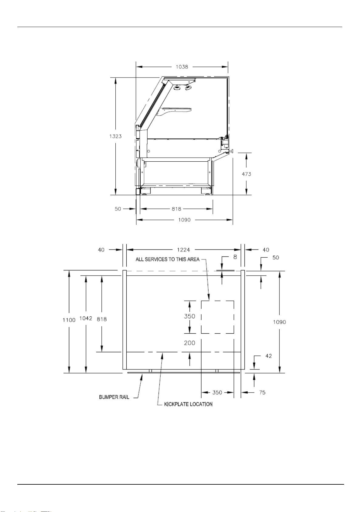
Case services dimensions 3
Operating environment 4
Handling and transporting cases 4
Shipping damages and shortages 4
Installation 5
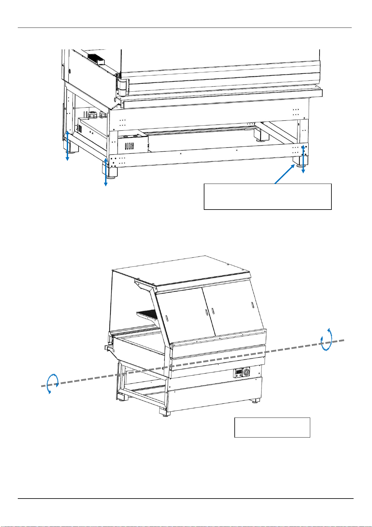
Positioning and levelling 5
Joining the cases 8
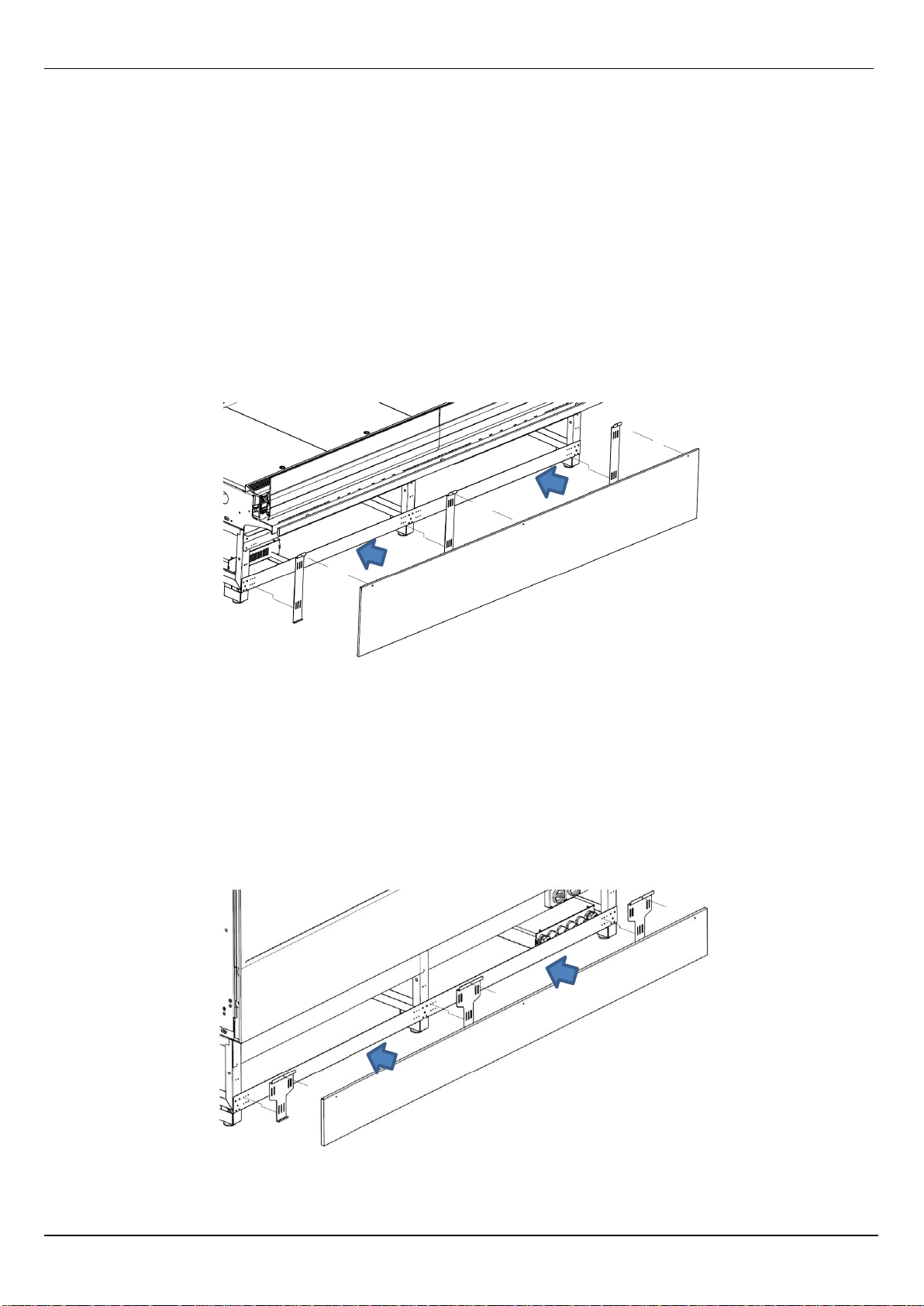
Attaching kick plates 9
Connecting power supply 11
Installing sensor probes 11
Mounting fixtures 12
Commissioning 13
Cleaning case 13
Starting up 13
Start-up checks 13
Decommissioning 13
Disposal 13
Operation 14
Loading Merchandise 14
Cleaning and Maintenance 14
Daily Checks 14
Cleaning 15
Important Notes 15
Cleaning Procedure 15
Six Monthly Maintenance 16
Operation Servicing 16
Troubleshooting 17
Appendixes 18
Appendix 1 Wiring diagrams 18
Appendix 2 Produce Engineering Datasheets 18
Appendix 3 Setting table 18
Appendix 4 Attaching case ends 18
Appendix 5 Top glass horizontal adjustment 20
Appendix 6 Front glass camber adjustment 22
Appendix 7 Risk analysis 23
Appendix 8 Controller 24
Appendix 9 Warranty 25

PRODUCT INSTALLATION MANUAL DH13 HOT FOOD
_________________________________________________________________________________________________________________________
Page 2 Hussmann
Pre installation
Important Safety Instructions
Please read the user manual carefully and store for later reference. In this document you will see these symbols with
following meanings
NOTE
Information in this manual is to be followed
in conjunction with specifications, work
practices and regulations of the customer,
installing company and relevant industry.
CAUTION
Care must be taken to avoid damage to
drainage outlets and electrical equipment
mounted under or at the rear of cases.
CAUTION
This symbol indicates electrical safety must
be concerned
WARNING
•Leave enough space to install the system. The space requirement will be instructed in “Pre-installation” section.
•Before installing the system make sure the power source is accessible to the cases array.
•All the power source has to be properly earthed.
•If any potential fail or product disconformity is investigated, please consult a qualified service technician.
•Always disconnect the power of the cases before conducting any service or maintenance.
•Keep the case out of direct sunlight, fire hazardous environment, or high moisture or humidity area.
•Fail to install the system as instructed in this manual may void Hussmann Warranty.

PRODUCT INSTALLATION MANUAL DH13 HOT FOOD
_________________________________________________________________________________________________________________________
Page 3 Hussmann
Case Services Dimensions
Fig (1) Service layout standard depth case

PRODUCT INSTALLATION MANUAL DH13 HOT FOOD
_________________________________________________________________________________________________________________________
Page 4 Hussmann
Operating Environment
All Hussmann Cases have been factory tested to AS1731, 25C at 60% RH. Hot food display cabinet is also tested to
AS4322.
Cases must not be positioned in areas that may be subject to cold or air currents such as ventilation ducts, open doors or
windows, direct sunlight, electric fans or ovens, etc. Otherwise the cabinet may show poor temperature performance or the
operating life is affected.
NOTE
Refer to product MSDS for all hazardous substances used
during installation in relation to their application, PPE, first aid,
disposal and emergency management. Refer page 20 (Risk
Analysis)
For MSDS sheet contact your Hussmann Representative
Handling and Transporting cases
Case dimensions can be found in the product engineering data sheets.
(This manual is a guide only. Always refer to the latest case information available from Hussmann Customer Service)
Always ensure that the moving device is of a suitable type, and has sufficient lifting capacity for the case weight and
dimension. Always lift cases from the underside.
Refer to and follow the manual handling policies of your Company when moving cases.
CAUTION
Care must be taken to avoid damage to drainage
outlets and electrical equipment mounted under or
at the rear of cases.
Shipping Damage and Shortages
If possible, it is recommended that packaging be removed from the cases before they are moved into the store.
After removing packaging, inspect the case for any shipping damage and ensure that all case inclusions, such as trims etc
are accounted for. Immediately report any shipping damage to the carrier and inform Hussmann Customer Service of any
short supplies.

PRODUCT INSTALLATION MANUAL DH13 HOT FOOD
_________________________________________________________________________________________________________________________
Page 5 Hussmann
Installation
NOTE
Information in this manual is to be followed in conjunction
with specifications, work practices and regulations of the
customer, installing company and relevant industry.
Positioning and Levelling
Each case has a unique identification number as follows:
##### - ## - ##
Job no. Line-up no. Case sequence no.
(within line-up)
Example: 106076.42.4 identifies this case in the 4th sequence of the line 42 for the job 106076.
As well as on the packaging, the case identification number appears as a serial number on the rating plate (most commonly
located on the ceiling panel left hand end of the case) refer to Fig (3) and is printed on a decal on the rear of the case ref
Fig (4). The case sequence number is also written on a ticket on the front panel.
Fig (3) Rating Plate
Fig (4) Decal rear of case with case sequence number

PRODUCT INSTALLATION MANUAL DH13 HOT FOOD
_________________________________________________________________________________________________________________________
Page 6 Hussmann
Cases must be positioned so that line-up numbers and case sequence numbers run in succession left to right standing in
front of the cabinet.
CAUTION
Ensure the lifting capacity of the trolley, etc. is
sufficient for the case. Refer to the product
engineering data tables and Risk Analysis (page 20).
To position the cases:
1. If the plinth surface is level, position the case designated as line up number 1 and case sequence number 1 in the
required position.
2. If the plinth surface is not level, determine where the highest point of the plinth is, and position the case allocated
to this position first.
3. Adjust the case height using the adjustable feet (if fitted) or metal shims (do NOT use timber) to ensure the case
is level to within +/- 1.5mm from front to back and side to side and chassis of case is NOT twisted. Maximum
25mm adjustment.
Fig (5) Levelling feet adjustment
NOTE
It is important that all cases are level for correct case joining and operation. If
cases are not properly levelled and positioned, door misalignment will be evident,
resulting in the job needing to be redone at complete cost to the installer.
Hussmann is not liable or responsible for the cost involved in fixing
problems arising directly from the installers’ failure to follow the
requirements outlined in this manual.
DO NOT SET CASE LEVELS OFF THE PATCH END fitted to a case.

PRODUCT INSTALLATION MANUAL DH13 HOT FOOD
_________________________________________________________________________________________________________________________
Page 7 Hussmann
Fig (6) Case Levelling
Fig (7) Case twisting
Make sure case is level:
Front to Back: +/- 1.5mm
Side to Side: +/- 1.5mm
Make sure all adjusting feet, NOT just the
ones at the end of the case, are adjusted
firmly to ensure case does not sag
Make sure Chassis of
case is NOT TWISTED.

PRODUCT INSTALLATION MANUAL DH13 HOT FOOD
_________________________________________________________________________________________________________________________
Page 8 Hussmann
Joining the Cases
Ensure cases are sealed before joining them to other cases
For instructions on attaching case ends, refer to appendix 4: attaching case ends
CAUTION
Do not walk or sit on cases.
To join the cases
1. Draw up the required case tightly against the case already in position
CAUTION
Case joining bolts should only be used,
with care, at the final pulling-up stage.
2. Ensure that the case is level, from front to back and side to side, with the existing case.
3. Insert the joining bolts, found in the blister pack, into the end holes and tighten –see Fig (9): joining hole locations
Fig (9) Joining holes location
Joining Holes

PRODUCT INSTALLATION MANUAL DH13 HOT FOOD
_________________________________________________________________________________________________________________________
Page 9 Hussmann
Attaching Kickplates
(This should be done after final Installation of Refrigeration and Drainage connections)
Attach kickplates and, if required, silicon seal to the floor once installation is complete and drains checked for water leaks.
Front Panel
1. Attached front panel and align with front skid rail refer figure 10.
2. Push front panel into bottom and top clips.
3. Check front panel is securely in position.
Fig (10) Attached front panel
Back Panel
1. Attached back panel and align with back skid rail refer figure 11.
2. Push back panel into bottom clip and over top clips.
3. Check back panel is securely in position.
Fig (11) Attached back panel

PRODUCT INSTALLATION MANUAL DH13 HOT FOOD
_________________________________________________________________________________________________________________________
Page 10 Hussmann
Side kickplate
1. Attached side kickplate as per drawing refer figure 12.
2. Adjust slot in kickplate to suit. Make sure kickplate is above floor.
3. Screw kickplate in position.
4. Check kickplate is securely in position.
Fig (12) Attached side kickplate

PRODUCT INSTALLATION MANUAL DH13 HOT FOOD
_________________________________________________________________________________________________________________________
Page 11 Hussmann
Connecting Power Supply
•The appliance must be installed so the power is accessible.
•To ensure that the appliance is not accidentally switched off, connect unit to its own power source. Do not
connect any other appliance using this source
•Size the cable according to AS3008 or relevant local standards. For power rating please refer to product
engineering datasheet for details.
Ensure the appliance is properly grounded (earthed).
Installing Sensor Probes
The DH13 range or cases have the probes pre fitted at the factory. Probe location as per Fig 14
CAUTION
Refer to relevant State or Territory legislation
relating to safe working heights.
Probe location:
1. 2 x Probe connected to rear of case.
Fig (14) Location of probe
SENSOR LOCATION

PRODUCT INSTALLATION MANUAL DH13 HOT FOOD
_________________________________________________________________________________________________________________________
Page 12 Hussmann
CAUTION
Do not walk or sit on cases.
Mounting fixtures
Replace racks and shelves etc, as necessary to store requirements
NOTE
Incorrect pan and display tag configurations
may compromise case performance.

PRODUCT INSTALLATION MANUAL DH13 HOT FOOD
_________________________________________________________________________________________________________________________
Page 13 Hussmann
Commissioning
Cleaning case
1. Remove the PVC protective coating on stainless steel, where applicable
2. Remove any residue, silicon or tape marks with a cloth moistened with rubbing alcohol
3. Remove all debris from in and around the case
4. Wipe case with a clean, damp cloth, if necessary
Starting up
1. Check supply power is ready and correct voltage. (by Licensed Person)
2. Confirm correct operation of RCD (if fitted) (by Licensed Person)
3. Turn case power on
Start-up checks –(by qualified persons only)
1. Check that all lights (and light RCDs, if installed) are working correctly.
2. Check the thermostat is set correctly (If installed).
3. Approximately 2 hours after start-up, check that the case is at correct operating temperature (refer the Product
Engineering Data).
Decommissioning
Plan and risk assess the decommissioning process to include the following:
1. Isolate the case from electrical systems. (Disconnection is to be undertaken by qualified persons only).
2. Removal of the case is to be in the reverse order of installation listed previously.
Disposal
Case disposal is to be carried out by the following:
1. Metal component removed and recycled
2. Remaining by commercial waste management

PRODUCT INSTALLATION MANUAL DH13 HOT FOOD
_________________________________________________________________________________________________________________________
Page 14 Hussmann
Operation
Loading Merchandise
Cases should only be stocked with merchandise for which they were manufactured as indicated by the case model number
on the rating plate (see Fig (15): Rating Plate) that is typically located, on the rear back panel at the lower right hand end
as viewed by the operator.
Fig (15): Rating Plate
Use only fittings and accessories supplied with the case or approved by Hussmann.
CAUTION
Do not climb in or on the case as this may result
in personal injury and/or case damage.
Cleaning and Maintenance
Daily Checks
•If an alarm system is not part of the refrigeration installation, the temperature of each case should be checked on
a daily basis via the thermometer that may be located inside the product area or via another reliable method.
The case temperature should be in the range of 60C - 65C when stabilised.
Up to three separate readings may have to be taken to ensure all the case temperature aren’t being taken during
thermostat cycling.
If it is consistently outside this range, contact Hussmann or your service contractor.
•Visually check the case for damage or spills and take appropriate remedial action.
CAUTION
If any damaged electrical components are
identified during inspection isolate case
power and contact service contractor.
•Visually inspect drain strainer and drain for any debris which could result in the drains becoming blocked with the
possibility of spilling on the floor creating a slip hazard

PRODUCT INSTALLATION MANUAL DH13 HOT FOOD
_________________________________________________________________________________________________________________________
Page 15 Hussmann
Cleaning
A thorough cleaning and service of the case should be carried out by qualified refrigeration and electrical engineers on a
six monthly basis. Please contact your service contractor.
Cases should also be cleaned by store staff on at least a weekly basis; some cases may, however, require more frequent
cleaning.
Important Notes
•Do not use hot water on cold glass surfaces as the glass may shatter and cause serious injury.
•Do not use abrasive, solvent, ammonia or oil-based cleaners.
•Do not use steam or a high-pressure system to clean the case.
•When flushing the waste drain, do not use high-pressure water hoses and be careful not to introduce water faster
than the waste outlet/drain can drain it.
Cleaning Procedure
1. Turn off power. Remove stock.
CAUTION
If case fan power is not isolated then staff should
wear hair nets and no jewellery or lose clothing.
The fan is protected by wire grill but the possibility
exists for items to be caught.
2. Remove all price tickets and any foreign materials from the case.
3. Clean glass or mirrored surfaces with a clean soft cloth and mild glass cleaner.
4. Wipe LAMP with a dry cloth.
5. Wipe down the exterior and interior of the case, paying particular attention to the perforations in the rear panels
and the air return grille with a clean soft cloth and mild soapy water.
6. Wipe over with clean dry cloth.
7. Remove the base trays, wash with mild soapy water and rinse.
8. Remove any foreign material from the base of the case.
9. Carefully flush the waste drain with a bucket of water and allow the base to drain.
10. Replace base trays and turn on power.
11. Allow the case to attain correct working temperature (approximately 30 minutes) and restock the shelves.

PRODUCT INSTALLATION MANUAL DH13 HOT FOOD
_________________________________________________________________________________________________________________________
Page 16 Hussmann
Six Monthly Maintenance
A thorough cleaning and maintenance check should be carried out on a six monthly basis by qualified and approved
refrigeration and electrical engineers. The following procedures should be undertaken as a minimum.
CAUTION
Cases should be electrically isolated
before carrying out any work that may
affect or expose electrical components.
1. Remove and clean the pan decks.
2. Remove any foreign material from the base of the case.
3. Check that all case panels, glass and trims are secure and undamaged.
4. Check for rust or paint damage.
5. Clean the air grilles on the cases.
6. Ensure all cable connections, including screw terminals, earth leads and straps, are secure.
7. Ensure insulation to all electrical components, including fan, (if any) controls, earth terminals and lights, are sound.
8. Carry out electrical safety tests, including earth continuity and insulation resistance.
9. Ensure that the correct fuse (circuit breaker) rating and type is fitted for all circuits.
With case power turned on:
10. Check that all lights and controls are working correctly.
11. Ensure light RCDs (if fitted) are working.
Operation Servicing
No servicing of Hussmann cases, is to be undertaken by store staff. Please contact your service contractor for all
maintenance queries.

PRODUCT INSTALLATION MANUAL DH13 HOT FOOD
_________________________________________________________________________________________________________________________
Page 17 Hussmann
Troubleshooting
ISSUE
POSSIBLE REASON
REMEDIAL ACTIONS
Product temperature is not
according to the PED sheet
Store condition is colder than climate class
3 (25°C/60%RH) or below 20°C
Check store air conditioner operation
Power Supply fault operating at
inappropriate settings or conditions
Check power supply and settings.
Case shelf arrangement has been deviated
significantly from original specified setup
Re-do the shelf arrangement as per
the original specification
Doors are not closed.
Ensure doors are kept closed
None of above
Contact Hussmann
ISSUE
POSSIBLE REASON
REMEDIAL ACTIONS
LAMP are not working
No power supply
Check supply is “on” and light
switch is working.
LAMP fittings
Call technician to check and
replace in necessary
LAMP failed
Replace LAMP
Table (1) General Troubleshooting

PRODUCT INSTALLATION MANUAL DH13 HOT FOOD
_________________________________________________________________________________________________________________________
Page 18 Hussmann
Appendixes
Appendix 1 Wiring diagrams –Supplied with each case.
Appendix 2 Product Engineering Datasheet –Supplied with each case.
Appendix 3 Setting Table –Part of PED.
Appendix 4 Attaching case ends
Appendix 5 Top glass horizontal adjustment
Appendix 6 Front glass door camber adjustment
Case ends are normally fitted in the factory; however, they occasionally need to be attached to a case on-site. Use this
procedure when an end attaches to a single case and when it is common to two cases.
Ensure that correct and appropriate manual handling techniques are applied when fitting a patch end.
Cases must be sealed before attaching case ends.
To attach a case end
1. Carefully run a knife around the inside rim of the end trim, taking care not to scratch the case end surface, and
remove the case end membrane.
2. To assist in screwing in the Lag screws, drill a 6mm hole in the mounting positions shown, using the 10mm diameter
fixing hole location. Ensure you do not drill completely through the End. see Fig (16)
Fig (16) Drill hole locations
(Inside Right hand End shown)
FRONT OF CASE
Fixing Holes

PRODUCT INSTALLATION MANUAL DH13 HOT FOOD
_________________________________________________________________________________________________________________________
Page 19 Hussmann
3. If the end is common to 2 cases, repeat step 2 for the other side of the case end.
4. Insert 2 hex nuts onto one of the lag screws, lock nuts together and drive screw through the hole at the top of the
case end until the lag is fully embedded in the end.
5. Remove the nuts from the lag screw and repeat step 4 for the remaining holes.
6. Pull up the case ends lightly against the case.
7. Adjust the case so that the end fits comfortably around the canopy and the top of the case and is level, from front
to back with the case roof.
8. Secure the case end with the lag screws and bolts
9. Apply either black or white silicon (depending on the interior colour of the case) all the way along the inside joins
between the case end and end frame. see Fig (17)
Fig (17) Silicon ends to case
10. Applying slight pressure, run your finger along the length of the silicon.
11. Remove all remaining packaging material from the case end and case and trim
12. Attach the end kickplate and, if required, silicon seal to the floor.
Apply
Silicone
Apply Silicone along
canopy
Table of contents
Other Hussmann Industrial Equipment manuals
Popular Industrial Equipment manuals by other brands

Zero
Zero AEROLYTE PRN 6060-A manual

ITRON
ITRON 60W Endpoint installation guide

Toro
Toro 301 High Lift quick start guide

Emerson Power Transmission
Emerson Power Transmission Kop-Flex KOP-GRID H Series Installation and Alignment Instructions

ABB
ABB 827E product manual

DUSTLESS BLASTING
DUSTLESS BLASTING MOBILE S DB500 user manual