INOXPA CPG Series Installation and user guide

INSTALLATION, SERVICE AND MAINTENANCE
INSTRUCTIONS
CPG AGITATOR FOR WINE
c/Telers, 54 Aptdo. 174
E-17820 Banyoles
Girona (Spain)
Tel. : (34) 972 - 57 52 00
Fax. : (34) 972 - 57 55 02
MICPG-01_EN
ED. 15.02/08
EC DECLARATION OF CONFORMITY
(In accordance with Directive 98/37/EC, annex II, part A)
We, the manufacturer: INOXPA, S.A.
c/ Telers, 54
17820 Banyoles (Girona) - Spain
Hereby declare that the products
WINERY AGITATOR CPG 200
Year of
Manufacture
Name Type
are in conformity with the provisions of the Council Directives:
Machine Directive 98/37/EC, and comply with the essential requirements of
said Directive and the harmonised standards:
UNE-EN ISO 12100-1/2:2003
UNE-EN 1050:1996
UNE-EN 294/A1/AC:1993
UNE-EN 953:1997
UNE-EN 563/A1/AC:2000
Low-Voltage Directive 2006/95/CE (replacing Directive 73/23/CE), and conform
to UNE-EN 60204-1:1997 and UNE-EN 60034-1/A11:2002.
Electromagnetic Compatibility Directive 2004/108/CE (replacing Directive
89/336/CE), and conform to UNE-EN 60034-1/A11:2002.
In conformity with Regulation (CE) No. 1935/2004 on materials and objects intended to
come into contact with foodstuffs (repealing 89/109/EEC), in accordance with which the
materials in contact with the product do not transfer its constituents to the foodstuffs in
quantities large enough to put human health at risk.
Declaration of Incorporation (Directive 98/37/EC, annex II, part B):
The aforementioned equipment shall not be commissioned until the
machine in which they will be incorporated has been declared as being in
conformity with the Machine Directive.
Josep Mª Benet
T
echnical mana
g
er
Ban
y
oles
,
Februar
y
2008
2013
december
2013

ED.15.02/08 1.Safety 3
1. Safety
1.1. INSTRUCTIONS MANUAL
This manual contains information about the receipt, installation, operation, assembly, disassembly and maintenance of the CPG
agitators.
The information published in the instruction manual is based on updated information.
INOXPA reserves the right to modify this instruction manual without prior notice.
1.2. START-UP INSTRUCTIONS
This instruction manual contains vital and useful information to appropriately handle and maintain your agitator.
Read these instructions carefully before starting up the agitator; become familiar with the operation and use of your agitator
and follow the instructions closely. These instructions should be kept in a safe location near the installation.
1.3. SAFETY
1.3.1. Warning symbols
Danger of injury caused by rotating
equipment parts.
Danger for persons in general
Electrical danger Danger! Caustic or corrosive agents.
Danger to the correct operation of the
equipment.
Danger! Suspended loads
Protective goggles requirement.Commitment to safety at the workplace.
1.4. GENERAL SAFETY INSTRUCTIONS
Read this instruction manual carefully before installing and starting the agitator. Contact INOXPA in
case of doubt.
1.4.1. During installation
The
Technical Specifications
of Chapter 8 should always be observed.
Check that the agitator anchoring is correct and that the shaft is perfectly aligned. Otherwise, this
may lead to serious mechanical problems in the agitator.
Check that the motor specifications meet the requirements, especially when working under
conditions that involve the risk of explosion.
During the installation, all the electric work should be carried out by authorised personnel.
1.4.2. During operation
The
Technical Specifications
of Chapter 8 should always be observed. Under no circumstances can the
limit values specified be exceeded.
NEVER touch the agitator during operation if it is being used in a hot-liquid tank due to the risk of
burns.
4 1.Safety MICPG-01_EN
The agitator contains moving parts. Never place your fingers inside the agitator while it is in
operation.
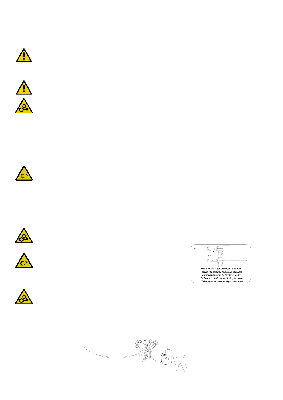
Remove the agitator before closing the valve.
NEVER spray the electrical motor directly with water. The standard protection for the motor is
IP- 55: Protection against dust and sprayed water.
The agitator cannot operate without fluid. Standard agitators are not designed to work during the
filling or emptying of tanks.
1.4.3. During maintenance
The
Technical Specifications
of Chapter 8 should always be observed.
NEVER disassemble the agitator until its temperature has decreased and can be handled safely.
Always use appropriate protective clothing while operating the agitator.
Do not leave parts loose on the floor.
ALWAYS disconnect the agitator from the power supply before starting maintenance work. Remove
the fuses and disconnect the cables from the motor terminals.
All electrical work should be carried out by authorised personnel.
1.4.4. Compliance with the instructions
Any non-fulfilment of the instructions may result in a risk for the operators, the environment and the machine, and may result
in the loss of your right to claim damages.
This non-fulfilment may result in the following risks:
•Failure of important functions of the machines/plant.
•Failure of specific maintenance and repair procedures.
•Possibility of electric, mechanical and chemical risks.
•Will place the environment in danger due to the release of substances.
1.4.5. Guarantee
Any warranty provided shall immediately be cancelled and void
ipso jure
, and INOXPA shall be compensated for any product
liability claim from third parties, if:
•the service and maintenance work was not carried out in accordance with the service instructions, or the repair work has
not been carried out by our personnel or it has been conducted without our written authorization;
•our equipment has been changed without prior written authorization;
•the parts or lubricants used are not original INOXPA parts and products;
•the materials were used incorrectly or negligently, or not in accordance with these instructions and their intended use;
•agitator parts were damaged by excessive pressure owing to the lack of a safety valve.
The General Delivery Terms already provided also apply.
No change can be made to the equipment without prior discussion with the manufacturer. For your
safety, please use original spare parts and accessories.
The use of other parts will exempt the manufacturer from any liability.
The service terms can only be changed with prior written authorisation from INOXPA.
Please do not hesitate to contact us in case of doubts or if more complete explanations are required on specific data
(adjustments, assembly, disassembly, etc.).

ED.15.02/08 2.Table of Contents 5
2. Table of Contents
1. Safety
1.1. Instructions manual......................................................................................................... 3
1.2. Start-up instructions........................................................................................................ 3
1.3. Safety............................................................................................................................. 3
1.4. General safety instructions............................................................................................... 3
2. Table of contents
3. General information
3.1. Description...................................................................................................................... 6
3.2. Range of application........................................................................................................ 6
4. Installation
4.1. Receiving the agitator...................................................................................................... 7
4.2. Transport and storage ..................................................................................................... 7
4.3. Location.......................................................................................................................... 8
4.4. Electrical installation........................................................................................................ 8
5. Start-up
5.1. Start-up.........................................................................................................................10
6. Operating problems
7. Maintenance
7.1. General information........................................................................................................12
7.2. Storage..........................................................................................................................12
7.3. Cleaning ........................................................................................................................12
7.4. Disassembly / assembly of the agitator............................................................................13
8. Technical Specifications
8.1. Technical Specifications ..................................................................................................14
8.2. Weights.........................................................................................................................14
8.3. CPG agitator dimensions.................................................................................................15
8.4. CPG-211A / B agitator exploded view...............................................................................16
8.5. CPG-211A / B parts list ...................................................................................................17
8.6. CPG-330 agitator - exploded view....................................................................................18
8.7. CPG-330 parts list...........................................................................................................19

6 3.General Information MICPG-01_EN
3. General Information
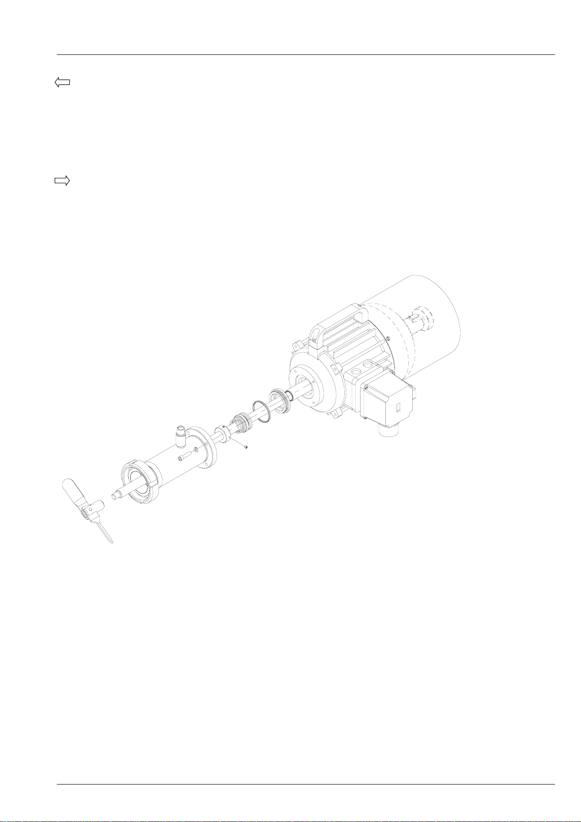
3.1. DESCRIPTION
CPG-series winery agitators are bottom side agitators. They are designed so that they can be installed and disassembled while
the tank is full of fluid, it is inserted through a valve without losing pressure and without using tools or special implements. This
design is based on the sliding agitation shaft and folding propeller that opens automatically when started up. Sealing is
achieved using a mechanical seal.
All the parts into contact with the fluid are manufactured in stainless steel, AISI-304 (1.4301). The surface finish is
electropolished. The standard agitation element is a type-12 folding propeller.
This equipment is suitable for use in food-processing.
3.2. RANGE OF APPLICATION
The CPG agitator main field of application is in the wine industry in general, maintaining solids in suspension, mixing wines
(blending), gasification (SO and CO
2 2), temperature homogenisation, syrup distribution, etc. The maximum tank volume for this
agitator is 100,000 litres with a viscosity of 1 to 100 cPs (depending on the characteristics of the fluid).
Each agitator has performance limits. The agitator was selected for a given set of agitation
conditions when the order was placed. INOXPA shall not be liable for any damage resulting from the
incompleteness of the information provided by the purchaser (nature of the fluid, viscosity, RPM,
etc.).

ED.15.02/08 4.Installation 7
4. Installation
4.1. RECEIVING THE AGITATOR
INOXPA cannot be held responsible for the damage sustained by the equipment during transport or
unpacking. Visually check that the packaging is not damaged.
The agitator will be accompanied by the following documents:
•Dispatch notes.
•Agitator Instructions and Service Manual.
Unpack the agitator and check:
•The agitator anchor connection, removing any remaining
packaging materials.
•Check that the agitator and the motor have not suffered any
damage.
•If the equipment is not in good condition and/or any part is
missing, the carrier should draw up a report accordingly as
soon as possible.
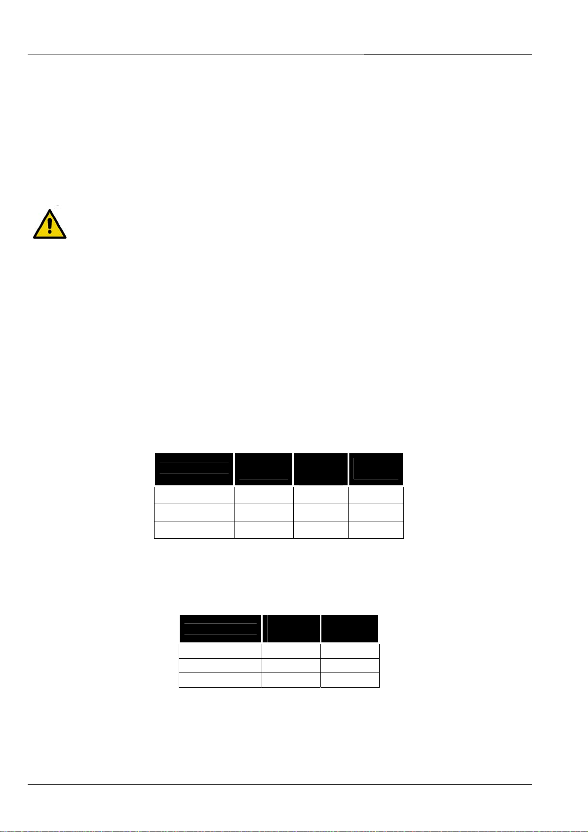
4.1.1. Identifying the agitator
YEAR
TYPE No.
KW min v Hz
Serial number QM3/h Hm IMPELLER
Agitator identification plate
4.2. TRANSPORT AND STORAGE
CPG agitators are often too heavy to be handled and stored manually.
Do not handle the agitator by the shaft as it may become deformed.
•Lift the agitator at the points indicated on the drawing.
•Secure the supports so that they can not slip.

8 4.Installation MICPG-01_EN
4.3. LOCATION
Once the agitator location has been determined, it must be fixed to the tank using the nut found on the discharge pipe and
firmly tightening it with the appropriate spanner.
Take into account that when fitting the agitator, to prevent any deformation the agitation shaft must not be struck or forced.
Install the agitator so as to allow sufficient ventilation.
If the agitator is installed outdoors, it should be protected by a roof. Its location should enable easy
access for any inspection or maintenance operations.
Force must never be applied on the end of the agitation shaft, since it can easily acquire a
permanent deformation.
The CPG-330 agitator must always be fixed by a support when mounted on the tank.
4.4. ELECTRICAL INSTALLATION
The connection of the electrical motors must be performed by qualified personnel.
Take all necessary measures to preventdamage to connections and cables.
The electrical equipment, terminals and components of the control systems may still contain electric
current when switched off. Contact with them may be dangerous for operators or cause irreversible
damage to the equipment.
Before handling the agitator, make sure that the engine is fully disconnected from the power.
•Connect up the motor following the manufacturer’s instructions.
•Check the direction of rotation (see the label on the agitator).
Start up the agitator motor briefly. Ensure that the direction is consistent with the one indicated on the plate. If the agitator
operates in the wrong direction, the folding propeller may fall into the tank.
ALWAYS check the direction of rotation of the motor with fluid inside the agitator.

ED.15.02/08 4.Installation 9
•The agitator is supplied with a connection ready for operation at 400 V (left photo). If the client has a 230 V, it should
change the connection as indicated in the photo on the right.
380 – 480V 220-280V
10 5.Start-up MICPG-01_EN
5. Start-up
Before starting the agitator, carefully read the instructions provided in Chapter 4. Installation.
5.1. START-UP
Read Chapter 8
Technical Specification
carefully. INOXPA cannot be held responsible for the incorrect
use of the equipment.
NEVER touch the agitator when working with high-temperature liquids.
5.1.1. Checks before starting up the agitator
yCheck that the agitator shaft is aligned and that it slides smoothly through the hollow shaft.
yCheck the level of fluid in the tank. When not specified in the order, the agitator cannot be operated during the filling or
emptying of the tank.
yOpen the valve where the agitator is fixed.
yIntroduce the shaft into the tank.
yRemove any air in the mechanical seal area by opening the drainage ports of the housing until liquid comes out.
The agitator must never operate when dry, as this may lead to serious damage to the mechanical
seal.
•Check that the power supply matches the rating indicated on the engine plate.
•Check that the motor’s direction of rotation is correct.
5.1.2. Checks when starting up the agitator
•Check that the agitator is not making any unusual noises.
•Check that there are no leaks through the sealed areas.
Introducing an object or solid raw material may cause the agitation component and other
mechanical parts to break and compromise its safety or guarantee.
Check the motor’s power consumption to avoid electric overload.
Remove the agitator shaft before closing the valve, as
indicated on the sticker found on the agitator.
Once the agitator is operational, take precautions to ensure that you do not put your hand on the
back of the agitator, inside the motor hood, because it contains rotating parts that may cause
serious personal injury.

ED.15.02/08 6.Operating Problems 11
6. Operating Problems
The following table provides solutions to problems that might arise during agitator operation. The agitator is assumed to have
been properly installed and correctly selected for the application.
Please contact INOXPA if technical assistance is required.
Operating Problems Probable causes
Motor overload 1, 2.
Not enough stirring. 1, 3, 4.
Vibration and noise. 5, 6, 7, 8, 9, 11.
Mechanical seal. 5, 10.
O-ring 7, 11.
Probable causes Solutions
1 Fluid viscosity too high Reduce the viscosity, e.g. by heating the fluid.
2 High density Reduce the propeller diameter.
3 Tank oversized for the agitator selected. Check with the Technical Dep.
4 Wrong direction of rotation Reverse the direction of rotation.
5 Liquid level too low or no liquid. Check the level of fluid in the tank.
6 Twisted shaft. Replace the shaft.
7 Scratched shaft. Replace the shaft.
8 Critical speed. Check shaft gap.
9 Brass bushings worn. Replace brass bushings.
10 Replace the mechanical seal
Mechanical seal damaged or worn.
11 O-ring damaged or worn. Replace the O-ring.
If the problems persist, stop using the agitator immediately. Contact the agitator manufacturer or
their representative.
12 7.Maintenance MICPG-01_EN
7. Maintenance
7.1. GENERAL INFORMATION
Like any other machine, this agitator requires maintenance. The instructions contained in this manual cover the identification
and replacement of spare parts. The instructions have been prepared for maintenance personnel and for those responsible for
the supply of spare parts.
Please carefully read Chapter 8
Technical Specification
.
All replaced material should be duly eliminated/recycled according to the directives in effect in the
area.
ALWAYS disconnect the agitator from the power supply before undertaking maintenance work.
7.1.1. Checking the mechanical seal
Regularly check that there are no leaks at the front of the motor. If there are leaks through the mechanical seal, replace it
following the instructions given under the Assembly and Disassembly section.
7.2. STORAGE
The agitator must be completely emptied of fluid before storage. If possible, avoid exposing the components of the agitator to
excessively damp environments.
7.3. CLEANING
The use of aggressive cleaning products such as caustic soda and nitric acid may cause burns to the
skin.
Use rubber gloves during the cleaning process.
Always use protective goggles.
If the agitator is installed in a system with a CIP process, it is not necessary to dismantle the agitator.
If there is no automatic cleaning process, dismantle the agitator as indicated in the Assembly and Disassembly section.
Cleaning solutions for CIP processes.
Only use clear water (chlorine-free) to mix with the cleaning agents:
a) Alkaline solution: 1% by weight of caustic soda (NaOH) at 70ºC (150ºF)
1 Kg NaOH + 100 l. of water = cleaning solution
o
2.2 l. NaOH at 33% + 100 l. of water = cleaning solution
b) Acid solution: 0.5% by weight of nitric acid (HNO ) at 70ºC (150ºF)
3
0.7 litres HNO at 53% + 100 l. of water = cleaning
3
Check the concentration of cleaning solutions; it may cause the deterioration of the watertight seals
of the agitator.
To eliminate the remains of cleaning products, ALWAYS carry out a final rinse on completion of the cleaning process.
ED.15.02/08 7.Maintenance 13
7.4. DISASSEMBLY / ASSEMBLY OF THE AGITATOR.
Disassembly
Remove the agitator through the valve to which it is fixed by means of the nut (45). Remove the agitator element (02, 02A) by
unthreading it from the agitator shaft (05). Remove the shaft (05) behind the motor (93) by sliding it off its hollow shaft. First
turn the pin (56A) properly in conjunction with the shaft turner (05A) at the end of the shaft. Remove the discharge pipe with
drainage port (01) joined to the motor with screws (51, 52 for CPG-330) and washers (53). Remove the stop ring (17) after
taking out the Allen pins (55). Remove the rotary part of the mechanical seal (08). Remove the seal cover (09) along with its
O-ring (80A). Remove the fixed part of the mechanical seal (08).
Assembly
Place the O-ring (80A) inside the seal cover (09). Place the stop ring (09) inside the motor flange housing (93). Carefully insert
the fixed part of the mechanical seal (08) into its housing inside the seal cover (09). Then, slide the rotary part of the
mechanical seal (08) over the motor shaft. Attach the stop ring (17) until it touches the motor shaft, and fasten the Allen pins
(55). Insert the agitator shaft (05) through the hollow shaft at the back of the motor. Insert the discharge pipe with drainage
port (01) and attach it to the motor with screws (51, 52 for CPG-330) and washers (53). Finally, attach the folding blades (02,
02A) by threading them onto the agitator shaft (05).
14 8.Technical Specifications MICPG-01_EN
8. Technical Specifications
8.1. TECHNICAL SPECIFICATIONS
Maximum viscosity ................................................................. 100 mPa.s.
Maximum pressure ................................................................. 2 bar
Maximum temperature ........................................................... +80ºC
+176 ºF
Noise level ............................................................................. 60-80 dB(A)
Anchor connection DIN 11851 (nut)
Use special protection when the noise level in the operation area exceeds 85 dB(A).
Materials
Parts in contact with fluid........................................ AISI 304
Other parts in stainless steel. ....................................... AISI 304
Gaskets in contact with fluid ................................... Viton
Other materials for optional gaskets ...................................... Check with the supplier
Surface finish ...................................................................... Sand blasted
Mechanical seal
Type of seal ........................................................................... Single interior seal
Stationary parts material ........................................................ graphite
Rotary parts material .............................................................. AISI 316L
Sealing material ..................................................................... EPDM
Agitator type Volume in
Power Speed
HO
[kW] [r.p.m.]
23
[m ]
CPG-211A
1.1 20 1390
CPG-211B
1.1 25-50 1390
CPG-330
3 50-100 1390
8.2. WEIGHTS
Agitator type Weight Weight
[Kg] [lbs]
CPG-211A
19 40
CPG-211B
19 42
CPG-330
42 92

ED.15.02/08 8.Technical Specifications 15
8.3. CPG AGITATOR DIMENSIONS
φdφH
DN ABCL
Agitator type
CPG-211A
50 / 2” 425 960 495 18 950 155
CPG-211B
50 / 2” 425 960 495 18 950 165
CPG-330
65 / 3” 465 1175 560 25 1145 200
16 8.Technical Specifications MICPG-01_EN
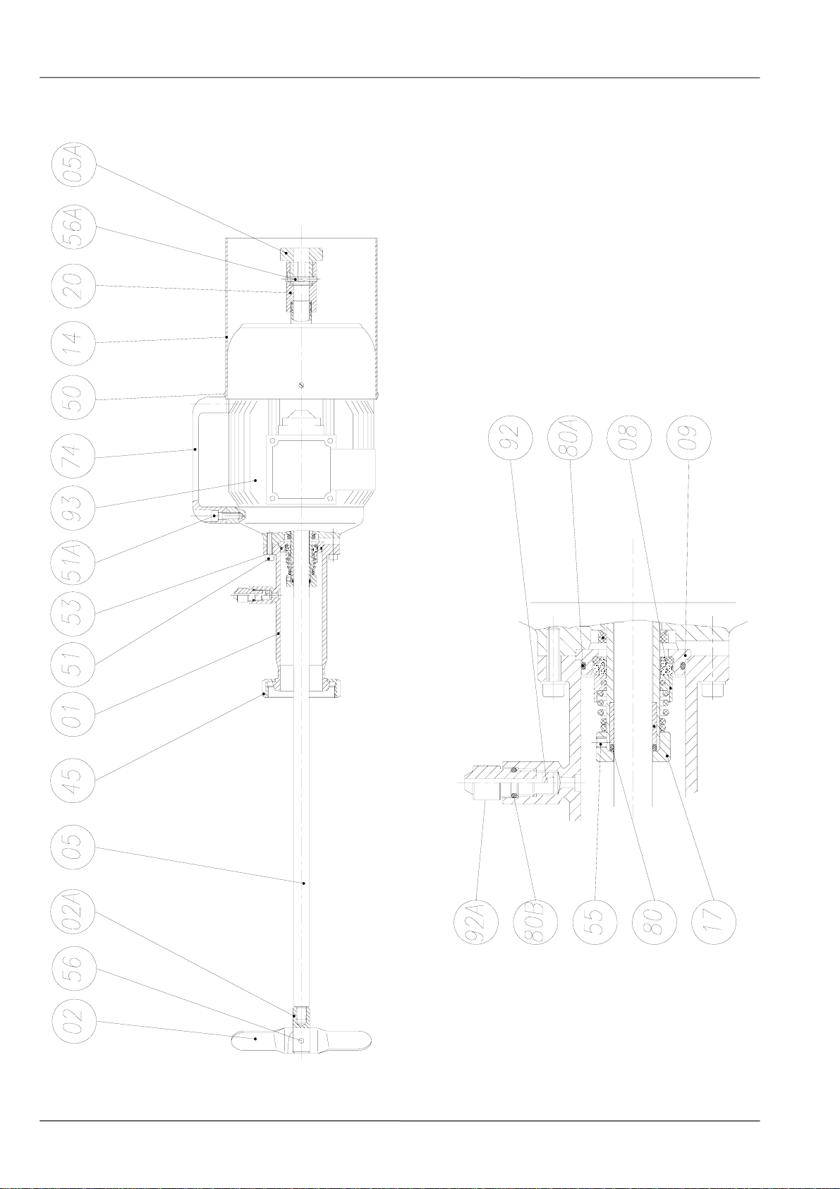
8.4. CPG-211A / B AGITATOR EXPLODED VIEW

ED.15.02/08 8.Technical Specifications 17
8.5. CPG-211A / B PARTS LIST
Position Description Quantity Material
01 Discharge pipe with drainage port 1 AISI 304
02 Blade 2 AISI 304
02A Blade holder 1 AISI 304
05 Agitator shaft 1 AISI 304
05A Shaft turner 1 AISI 304
08 Mechanical seal * 1 -
09 Seal cover 1 AISI 304
14 Motor hood 1 AISI 304
17 Stop ring 1 AISI 304
20 Centring pipe 1 Brass
45 Nut 1 AISI 304
50 Screw 4 A2
51 Allen screw 4 A2
51A Allen screw 2 A2
53 Grower washer 4 A2
55 Allen pin 2 A2
56 Blade pin 1 AISI 304
56A Pin 1 AISI 304
74 Handle 1 Engineering plastic
80 O-ring * 1 FPM
80A O-ring * 1 FPM
80B O-ring 1 FPM
92 Drainage shaft 1 AISI 304
92A Drainage knob 1 PTFE
93 Hollow-shaft motor 1 -
(*) Recommended spare parts
18 8.Technical Specifications MICPG-01_EN
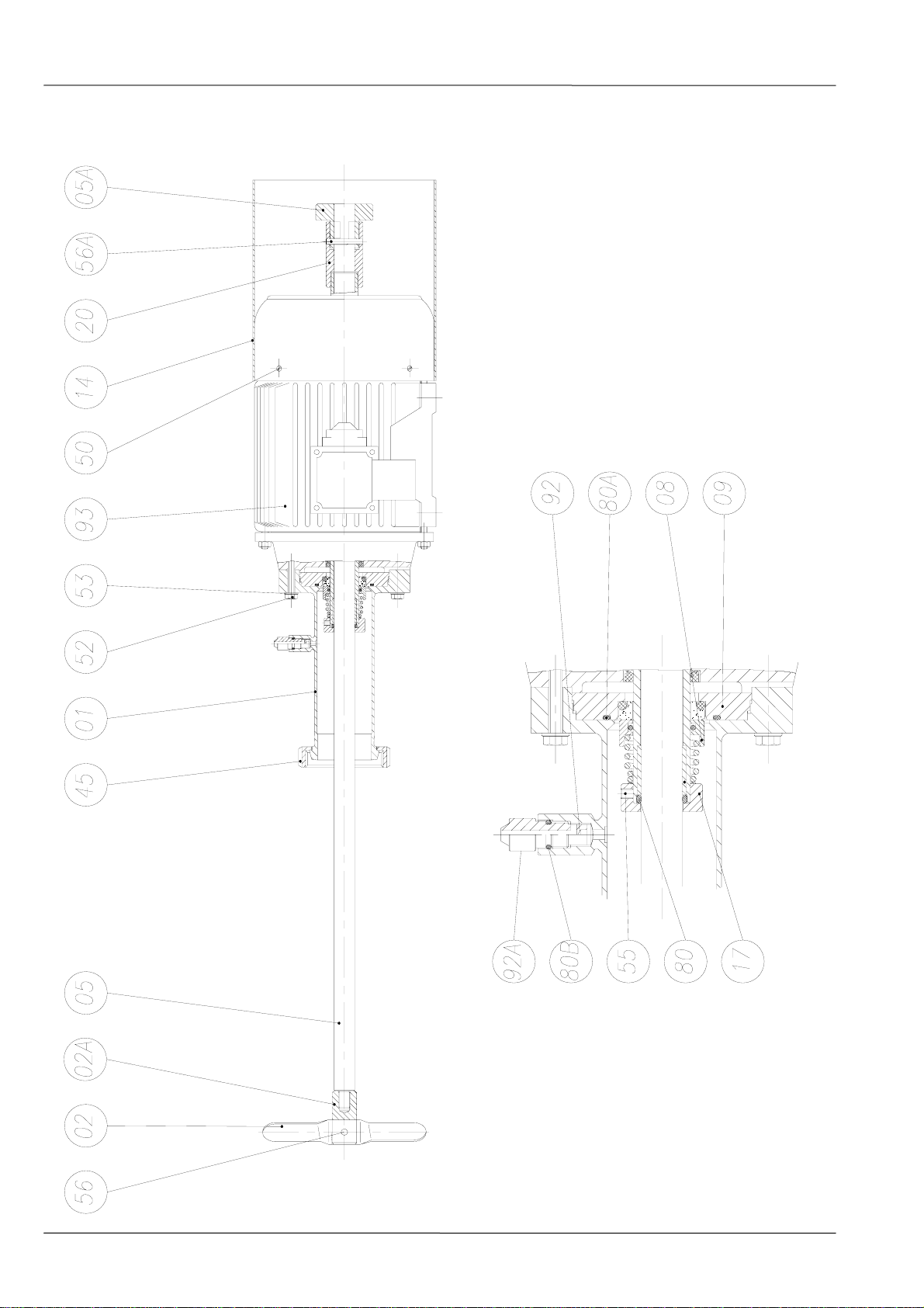
8.6. CPG-330 AGITATOR - EXPLODED VIEW

ED.15.02/08 8.Technical Specifications 19
8.7. CPG-330 PARTS LIST
Position Description Quantity Material
01 Discharge pipe with drainage port 1 AISI 304
02 Blade 2 AISI 304
02A Blade holder 1 AISI 304
05 Agitator shaft 1 AISI 304
05A Shaft turner 1 AISI 304
08 Mechanical seal * 1 -
09 Seal cover 1 AISI 304
14 Motor hood 1 AISI 304
17 Stop ring 1 AISI 304
20 Centring pipe 1 Brass
45 Nut 1 AISI 304
50 Screw 4 A2
52 Hexagonal screw 4 A2
53 Grower washer 4 A2
55 Allen pin 2 A2
56 Blade pin 1 AISI 304
56A Pin 1 AISI 304
80 O-ring * 1 FPM
80A O-ring * 1 FPM
80B O-ring 1 FPM
92 Drainage shaft 1 AISI 304
92A Drainage knob 1 PTFE
93 Hollow-shaft motor 1 -
(*) Recommended spare parts

Мешалки для виноделия — Боковая мешалка CPG
http://k-tep.com.ua/
Office +38 044 2091823
МТС +38 066 9076563
Kиевстар +38 098 3676414
Skype: k-teppumps
Замечания
Условия поставки:DDP склад г. Киев
Заметки
Время поставки рассчитано согласно дате предложения иизменяется взависимости от даты
подтверждения заказа.
Размещая заказ, покупатель принимает предложение ивсе спецификации, характеристики и
условия, указанные вданном документе.
This manual suits for next models
3
Table of contents
Other INOXPA Industrial Equipment manuals

INOXPA
INOXPA MCR Ex Manual

INOXPA
INOXPA INNOVA Mini N Manual

INOXPA
INOXPA KIBER KSF Ex Manual

INOXPA
INOXPA SLR Ex Manual

INOXPA
INOXPA BFI Manual

INOXPA
INOXPA BCI Series Manual

INOXPA
INOXPA KIBER KS Ex Manual

INOXPA
INOXPA NHS VERTICAL AGITATOR Ex Manual

INOXPA
INOXPA HYGINOX Ex SE Manual

INOXPA
INOXPA MM-1 Manual

Popular Industrial Equipment manuals by other brands

Condair
Condair Defensor OptiSorp Installation and operating instructions

KMT
KMT STREAMLINE SL-V SRP 100 Operation and maintenance manual

Lamtec
Lamtec BT300 BurnerTronic manual

TRAK
TRAK SAND TRAK ST1-075A la Owner's/operator's manual

Brano
Brano Z420-A Operation manual

Station Road Steam
Station Road Steam STAFFORD Assembly instructions


