InoTec inoCOMB Cabrio Installation instructions
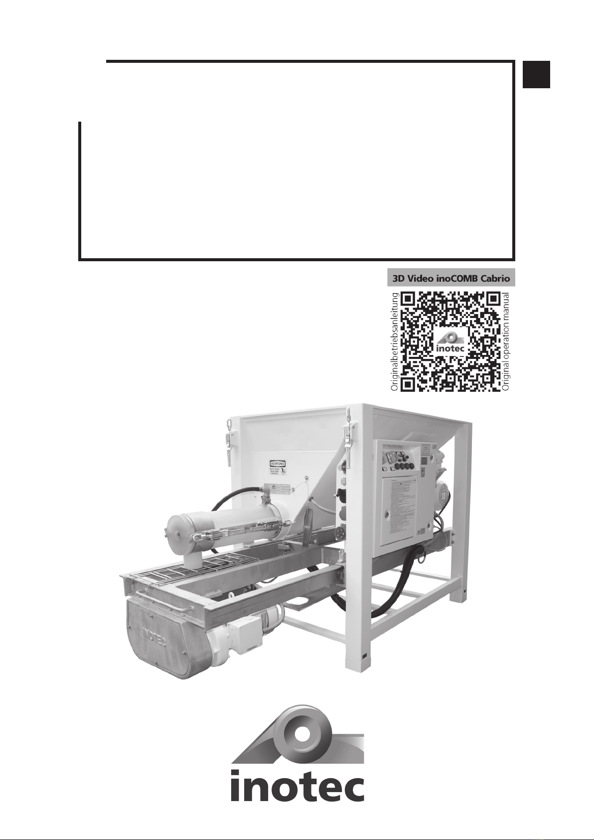
EN
Original Operating Manual
Small Silo inoCOMB Cabrio
Read this entire original operating manual before starting work.

EN
Page 2
Thank you for trusting INOTEC. By purchasing you have opted for a quality product.
If you have any suggestions or any issues, we would be delighted to hear your suggestions for improvement
and
your feedback. Speak to the sales representative
assigned to you or, in urgent cases, contact us directly.
We work constantly to further develop our products and reserve the right to make changes for technical reasons
relating to building legislation.
Yours faithfully
INOTEC GmbH
Legal notice
Address: INOTEC GmbH
Daimlerstraße 9-11
79761 Waldshut-Tiengen
Germany
Tel.: +49 (0)7741 6805 666
Fax: +49 (0)7741 6805 665
Web: www.inotec-gmbh.com
Status: September 2021
Document number: 10042612-OBA-DE

Page 3
Inhalt
1 General information.................................................................................................................................. 6
1.1 Information about this manual ........................................................................................................................6
1.2 Symbol explanation ..........................................................................................................................................6
1.3 Information about this manual ........................................................................................................................6
1.3.1 Purpose of this operating manual...................................................................................................................................6
1.3.2 Disclaimer ......................................................................................................................................................................6
1.3.3 Warranty........................................................................................................................................................................6
1.3.3.1 Exercising claims .........................................................................................................................................................6
1.3.3.2 Warranty claims ..........................................................................................................................................................7
1.3.4 Carrying out repairs .......................................................................................................................................................7
2 Safety.......................................................................................................................................................... 7
2.1 Intended use ......................................................................................................................................................7
2.2 General risk sources...........................................................................................................................................8
2.2.1 Notices in the operating manual.....................................................................................................................................8
2.2.2 Performing checks before starting work .........................................................................................................................8
2.2.3 Conversions and changes...............................................................................................................................................9
2.2.4 Cleaning and maintaining the machine ..........................................................................................................................9
2.2.5 Changing the location of the machine ...........................................................................................................................9
2.3 Notices on the machine ....................................................................................................................................9
2.4 Personnel qualification....................................................................................................................................10
2.5 Responsibility of the operator........................................................................................................................10
2.6 Personal protective equipment (PPE).............................................................................................................10
3 Technical data........................................................................................................................................... 11
3.1 Rating plate .....................................................................................................................................................11
3.2 Electric control system, pump output, particle size, weight, dimensions ...................................................11
3.3 Mortar pressure gauge....................................................................................................................................11
3.4 Water measuring system.................................................................................................................................11
3.5 Material container ...........................................................................................................................................11
3.6 Mixer motor .....................................................................................................................................................11
3.7 Pump motor .....................................................................................................................................................11
3.8 Metering shaft .................................................................................................................................................11
3.9 Mixing shaft.....................................................................................................................................................11
3.10 Pump shaft .....................................................................................................................................................11
3.11 Rotor/Stator ...................................................................................................................................................12
3.12 Noise emission ...............................................................................................................................................12
3.13 Operating conditions.....................................................................................................................................12
4 Assembly and function ........................................................................................................................... 12
4.1 Scope of delivery inoCOMB Cabrio ................................................................................................................12
4.2 Functionality ....................................................................................................................................................12
4.3 Sequence of assembly.....................................................................................................................................13
4.4 Components.....................................................................................................................................................14
4.4.1 Description of the components ....................................................................................................................................14
4.4.1.1 Frame with pull-out frame for pump hopper, material hopper, water supply button and vibrator...............................15
4.4.1.2 Switching cabinet .....................................................................................................................................................15
4.4.1.3 Drive unit for the mixer .............................................................................................................................................15
4.4.1.4 Water measuring system ...........................................................................................................................................15
4.4.1.5 Mixing tube inoPOWER Mix with mixing shaft and mixing tube cover........................................................................15
4.4.1.6 Drive unit for the feed pump, incl. chain gear box and pump hopper ........................................................................15
4.5 Displays and controls ......................................................................................................................................16
4.5.1 Switching cabinet ........................................................................................................................................................16
4.5.1.1 Pump on/off switch and reset....................................................................................................................................16
4.5.1.2 Mixer on/off switch...................................................................................................................................................16
4.5.1.3 Reverse pump ...........................................................................................................................................................16
4.5.1.4 Probe On/Off ............................................................................................................................................................16
4.5.1.5 Pump speed..............................................................................................................................................................16
4.5.1.6 Illuminated button Cover grille..................................................................................................................................16
4.5.1.7 Illuminated button Water pressure ............................................................................................................................16
4.5.1.8 Illuminated sensor Mortar pressure............................................................................................................................16
4.5.1.9 Illuminated button Remote control............................................................................................................................16

EN
Page 4
4.5.2 Pump unit (pump motor, pump shaft, rotor/stator and mortar pressure gauge) ............................................................17
4.5.3 Mixing unit (metering shaft and mixing tube with mixing shaft) ...................................................................................17
4.5.4 Water measuring system ..............................................................................................................................................17
4.5.4.1 Installing the water measuring system.......................................................................................................................18
4.6 Connections......................................................................................................................................................18
4.6.1 Power connections (230 / 400 V) ................................................................................................................................18
4.6.2 Connections of the water measuring system ................................................................................................................19
4.7 Operating modes.............................................................................................................................................19
4.9 Spare parts and diagrams ...............................................................................................................................24
4.9.1 Overview of the individual assemblies of the small silo..................................................................................................24
4.9.2 Drive unit for the mixer ................................................................................................................................................25
4.9.3 Pump hopper...............................................................................................................................................................26
4.9.4 Drive unit incl. chain gear box and pump hopper ........................................................................................................27
4.9.5 Drive shaft in the pump hopper....................................................................................................................................28
4.9.6 Water measuring system ..............................................................................................................................................29
4.9.7 Switching cabinet inside (Level 1) .................................................................................................................................30
4.9.8 Switching cabinet inside (Level 2) .................................................................................................................................31
4.9.9 Switching cabinet left and right side, underside............................................................................................................31
4.9.10 Switching cabinet front..............................................................................................................................................32
4.9.11 Mixing tube inoPOWERMIX “S” Plus with mixing shaft and mixing tube cover ...........................................................33
4.9.12 Mixing tube cover for inoPOWERMIX “S” & “L” mixing tube (Art. No. 10044008).....................................................34
4.9.13 Mixing shaft for inoPOWERMIX “S” & “L” mixing tube..............................................................................................34
4.9.14 Metering shaft ...........................................................................................................................................................34
4.9.15 Pump shaft for set “D” and “Ü”................................................................................................................................35
4.9.16 Rotor/Stator ...............................................................................................................................................................35
4.9.17 Set “D” .....................................................................................................................................................................36
4.9.18 Set “Ü1” ...................................................................................................................................................................36
4.9.19 Set “Ü2” ...................................................................................................................................................................37
4.9.20 Set “RS” ....................................................................................................................................................................37
5 Transport and storage ............................................................................................................................. 38
5.1 Safety instructions for transport ....................................................................................................................38
5.2 Transport inspection........................................................................................................................................38
5.3 Damage report.................................................................................................................................................38
5.4 Complaints .......................................................................................................................................................38
5.5 Packaging .........................................................................................................................................................38
5.6 Transporting the used machine in the vehicle...............................................................................................38
5.7 Storage .............................................................................................................................................................38
6 Installation ............................................................................................................................................... 39
6.1 Delivery condition of the machine.................................................................................................................39
6.2 Assembling the pump unit (pump shaft, rotor, stator and pressure gauge with hose coupling).............40
6.3 Mounting the metering and mixing shaft with mixing tube.......................................................................40
6.4 Installing the water measuring system..........................................................................................................41
6.5 Regulation of the water pressure...................................................................................................................42
6.6 Material preparation .......................................................................................................................................42
6.7 Adjusting the material consistency ................................................................................................................42
6.8 Preparing the machine ....................................................................................................................................42
6.9 Starting the machine.......................................................................................................................................43
7 Commissioning ....................................................................................................................................... 43
7.1 Adding material to the material hopper........................................................................................................43
7.2 Changing the material.....................................................................................................................................43
7.3 Change of location on the construction site .................................................................................................44
8 Operation, use.......................................................................................................................................... 44
8.1 Checking operating behaviour .......................................................................................................................44
8.2 Checking the consistency of the material......................................................................................................44
8.3 Correcting flow fluctuations...........................................................................................................................44
8.4 Work break/end of work.................................................................................................................................44
9 Areas of application ................................................................................................................................ 45

Page 5
EN
Chapter Inhalt
10 Cleaning & decommissioning ............................................................................................................... 45
10.1 Cleaning process............................................................................................................................................46
10.2 After cleaning ................................................................................................................................................47
10.3 Decommissioning...........................................................................................................................................48
11 Maintenance........................................................................................................................................... 49
11.1 Maintenance plan..........................................................................................................................................49
11.2 Dirt trap sieve in the water inlet..................................................................................................................49
11.3 Dirt trap sieve in the pressure reducing valve.............................................................................................49
11.4 Set values .......................................................................................................................................................49
11.5 Wear limits .....................................................................................................................................................50
11.5.1 Metering shaft wear limit..........................................................................................................................50
11.5.2 Mixing shaft wear limit..............................................................................................................................50
11.5.3 Pump shaft wear limit................................................................................................................................50
12 Dismantling and disposal ..................................................................................................................... 55
12.1 Safety..............................................................................................................................................................55
12.2 Dismantling....................................................................................................................................................55
12.3 Disposal ..........................................................................................................................................................55
13 Systems................................................................................................................................................... 56
13.1 EC declaration of conformity........................................................................................................................56
13.2 General Terms of Business of the company INOTEC GmbH........................................................................57
13.3 Feeding and earthing ....................................................................................................................................58
13.3.1 Circuit diagram: Load circuits 01 ................................................................................................................................59
13.3.2 Circuit diagram: Load circuits 02 ................................................................................................................................60
13.3.3 Circuit diagram: Direction of rotation changeover ......................................................................................................61
13.3.4 Circuit diagram: Contactor control .............................................................................................................................62
13.3.5 Circuit diagram: Sensors.............................................................................................................................................63
13.3.6 Circuit diagram: Operating switch..............................................................................................................................64
13.3.7 Circuit diagram: Pump ...............................................................................................................................................65
13.3.8 Circuit diagram: Nano 01...........................................................................................................................................66
13.3.9 Circuit diagram: Nano 02...........................................................................................................................................67
13.3.10 Circuit diagram: Nano 03.........................................................................................................................................68
13.3.11 Circuit diagram: Nano 04.........................................................................................................................................69
14 Order form.............................................................................................................................................. 70
15 Index ....................................................................................................................................................... 71
16 Locations ................................................................................................................................................ 72

Page 6
EN
Chapter 1 General information
1 General information
1.1 Information about this manual
• This manual helps to ensure safe and efficient use of
the machine.
• Operating personnel must have carefully read through
and understood this manual before starting any work.
• Compliance with all the specified safety instructions is
a basic prerequisite for working safely.
• This manual is a component of the machine and must
be stored within direct proximity of the machine, acces-
sible to operating personnel at all times.
• In addition to the notices in these instructions, the local
accident prevention guidelines and national occupa-
tional health regulations also apply.
1.2 Symbol explanation
Hazard notices feature symbols to make them easier to
identify. These indicate the severity of the hazard.
• You must observe this information.
!
DANGER DANGER indicates an immediate hazard.
Death or serious injuries may result from non-compliance.
!
WARNING WARNING indicates a potentially dangerous
situation. Death or serious injuries may result from a failure
to avoid these situations.
!
CAUTION CAUTION indicates a potentially dangerous
situation. Minor or slight injuries may result from failure to
avoid these situations or damage to the machine or some-
thing in its vicinity.
NOTE
NOTICE draws your attention to useful tips for
effectively handling the machine.
1.3 Information about this manual
1.3.1 Purpose of this operating manual
The operating manual is used to provide information to the
operating manager, assembly fitters and machine operators
on the construction site. It contains important instructions
for safe use, optimum results and a long service life.
!
DANGER Risk of incorrect operation.
Failure to observe the operating manual could put the
operator’s life and health at risk and damage the ma-
chine.
• Read this operating manual carefully before passing it
on to your assembly fitters or operators.
• Please ensure that assembly fitters and operators read
this operating manual carefully before they start install-
ing and commissioning the machine.
• Always keep the operating manual to hand and in a leg-
ible condition.
1.3.2 Disclaimer
All technical information, data and instructions for use con-
tained in this operating manual reflect the state of the art at
the time of printing and are based on our experience thus
far and the best of our knowledge.
The manufacturer cannot be held liable for any damages as
a result of:
• Failure to comply with this manual
• Improper use
• Assignment of non-trained personnel
• Unauthorised alterations
• Technical changes
• Use of non-approved spare parts
1.3.3 Warranty
Statutory warranty periods of 12 months from the date of
purchase/the date of invoice of the industrial end customer
apply to our machinery.
1.3.3.1 Exercising claims
In the event of a warranty claim, send the entire machine,
along with the invoice, to our headquarters in Waldshut-
Tiengen.
Contact our free INOTEC service hotline beforehand on
+49 7741 6805 777.

Page 7
EN
Chapter 2 Safety
1.3.3.2 Warranty claims
Claims apply only where material or manufacturing faults
exist and where machinery has been used properly. Wear
parts are not covered by the warranty. All claims shall be-
come void if third-party parts are installed, where the ma-
chinery has been improperly used or stored and in the event
of obvious non-compliance with the operating manual. In
this connection, we refer you to our General Terms of Busi-
ness.
1.3.4 Carrying out repairs
Repairs may only be carried out by employees at our INO-
TEC service centres.
2 Safety
2.1 Intended use
You may only operate this machine if the following
conditions are met:
• The small silo inoCOMB Cabrio is suitable for mixing,
conveying and spraying or placing all factory premixed
and machine-compatible dry mortars, screed materials
and floor levelling compounds. The machine can be
fed with powdered material from sacks, from one-way
containers (with the inoFLEX Duo dry conveying unit),
from big bags (with an attachment bonnet or with the
big bag box Mono).
• In the mixing phase, a paste-like product is created by
adding water.
• The material is pumped to the processing location by
means of mortar hoses. There, it is applied to walls
and ceilings with appropriate spray/adhesive guns or a
reprofiling sprayer or poured directly onto the floor.
• Only use the machine within its limits of application
and according to the technical data.
• Pay particular attention to the safety and warning
notices outlined in this original operating manual.
!
DANGER Failure to use the inoCOMB Cabrio, the
user is threatened with danger to life and limb as
well as impairment of the inoCOMB Cabrio or other
assets.
!
WARNING Danger due to misuse!
Misuse of the inoCOMB Cabrio can lead to dangerous
situations.
• Never use the inoCOMB Cabrio small silo to produce oth-
er products such as food.
• Never use the small silo inoCOMB Cabrio outside the val-
ues specified in the “Technical data”.

Page 8
EN
Chapter 2 Safety
2.2 General risk sources
!
DANGER Electrical voltage.
Danger of death due to electric shock.
• Work on the electronic control system may only be per-
formed by a qualified electrician.
• Switch off the machine and pull out the mains plug.
• Secure the machine against unexpectedly being switched
back on.
• Connect the mixing pump only to regulation construc-
tion site power distribution points with type B FI circuit
breakers (30 mA).
• The connection must be fused with 32 A.
• The cross-section of the supply cable is at least 4.0 mm2
at 400 V 3 PH
• Connect the supply cable to the feed-in connector of the
switching cabinet.
• All operating equipment on the construction site must
generally be connected according to BGI/GUV-I 608.
!
DANGER Rotating mixing, metering and pump
shafts. Danger of death due to being pulled into the
machine and crushed.
When the motors are running, the metering shaft ro-
tates in the material hopper, the mixing shaft in the
mixing tube and the pump shaft in the pump hopper.
• Do not reach into the rotating mixing or pump shaft.
• Do not bring any objects into the rotating mixing or
pump shaft.
1. Before working on the mixing or pump shaft, disconnect
the external power supply (main switch off). Only loosen
the screw of the protective grids when the machine is
switched off.
2. Pull out the mains plug.
3. Secure the machine against unexpectedly being switched
back on.
!
DANGER Pressurised conveyor hoses.
Risk of injury and risk of property damage due to es-
caping and/or flying material, and/or bursting con-
veyor hoses.
• Before disconnecting the conveyor hoses, make sure that
the hoses are depressurised. To do so, check the pressure
indicator on the mortar pressure gauge. The pressure in-
dicator must display 0 bar!
• Before opening the hose coupling, let the small silo ino-
COMB Cabrio run in reverse to release any pressure! To do
this, press the “Reverse pump” pushbutton until the pres-
sure display on the mortar pressure gauge shows 0 bar.
Pushbutton “Reverse pump”
• Use only conveyor hoses which are permissible with an
operating pressure of 40 bar and a burst pressure of 120
bar, and are in a technically perfect condition (e.g. are
without any cracks or other external damage!).
!
WARNING Water jet.
Risk of injury and risk of property damage due to es-
caping water.
1. Interrupt the external water supply by closing the water
valve.
2. In order to release the pressure (approx. 2 bar), open
the water drainage valve on the water measuring sys-
tem under the pressure reducer.
3. Remove the hose from the external water supply.
4. Do not point the water jet at other people or yourself.
2.2.1 Notices in the operating manual
!
CAUTION Safety notices in the operating manual
alert the operating personnel to any immediate dan-
ger. Please observe all the technical and hazard notic-
es in this operating manual.
2.2.2 Performing checks before starting work
!
WARNING Defects or damage can put the safety of
operating personnel at risk and impair the functional-
ity of the machine.
• Before commencing work, check the machine for any
obvious external damage or defects.
• Do not commission the machine if you notice any dam-
age to or defects in the machine or to the conveyor hos-
es.
• Ensure that the damage and/or defects are rectified.

Page 9
EN
Chapter 2 Safety
2.3 Notices on the machine
!
DANGER Safety notices on the machine make oper-
ating staff aware of imminent danger.
The following warning labels are attached to the small silo
inoCOMB Cabrio:
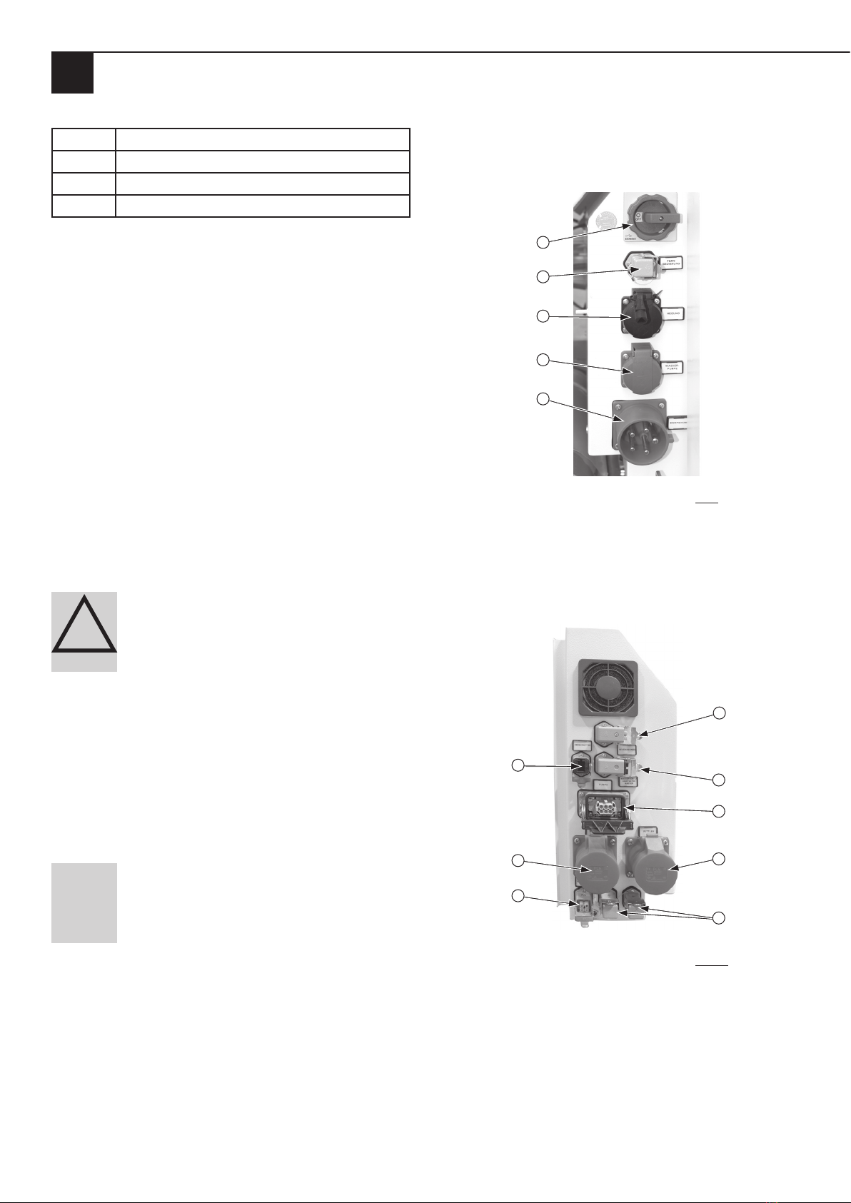
Instructions on the switching cabinet:
• Pull out the mains plug before opening the housing! (1).
• The unit may only be operated via a plug-in device that is
protected by an RCD (FI) IDh ≤ 30 mA type B (2)
• WARNING! According to DGUV V3, a retest is required
after every electrical modification to the machine (3).
• This QR code will redirect you to the original operating
instructions of the small silo and to a 3D animation of
how it works (4).
• Short operating instructions (5)
• WARNING! Do not switch the machine on again for
60 seconds after it has been switched off by the main
switch or due to a power failure (notice on the right, on
the side of the switching cabinet) (6).
1234 65
Note on the fold-away motor of the mixing pump:
• Before opening, bring the engine to a standstill! (7).
7
2.2.3 Conversions and changes
!
DANGER Conversions or changes can put the safe-
ty of operating staff at risk and impair the functional-
ity of the machine.
• Do not make any changes, additions or conversions to
the machine without first consulting INOTEC GmbH
and obtaining its written approval. Otherwise, the op-
erating license will become void.
2.2.4 Cleaning and maintaining the machine
!
WARNING Cleaning and maintenance work can put
the safety of operating staff at risk and impair the
functionality of the machine.
1. Switch off the machine and pull out the mains plug.
2. Secure the machine against unexpectedly being
switched back on.
3. Before cleaning with the water jet, cover all the open-
ings that water must not penetrate into for safety and
functional reasons.
4. After cleaning, remove all the covers which were at-
tached to protect against the water.
2.2.5 Changing the location of the machine
The small silo inoCOMB Cabrio can be moved on the con-
struction site with a pallet truck or a forklift.
!
CAUTION Changing location can put the safety of
operating staff at risk and impair the functionality of
the machine.
1. Switch off the machine and pull out the mains plug.
2. Move the machine to a new location on the building
site.
3. Always install the machine in such a way that it is level
and stable.
4. Secure the machine against undesirable movements.
5. Reconnect the machine to the external power supply
before restarting the machine.
Page 10
EN
Chapter 2 Safety
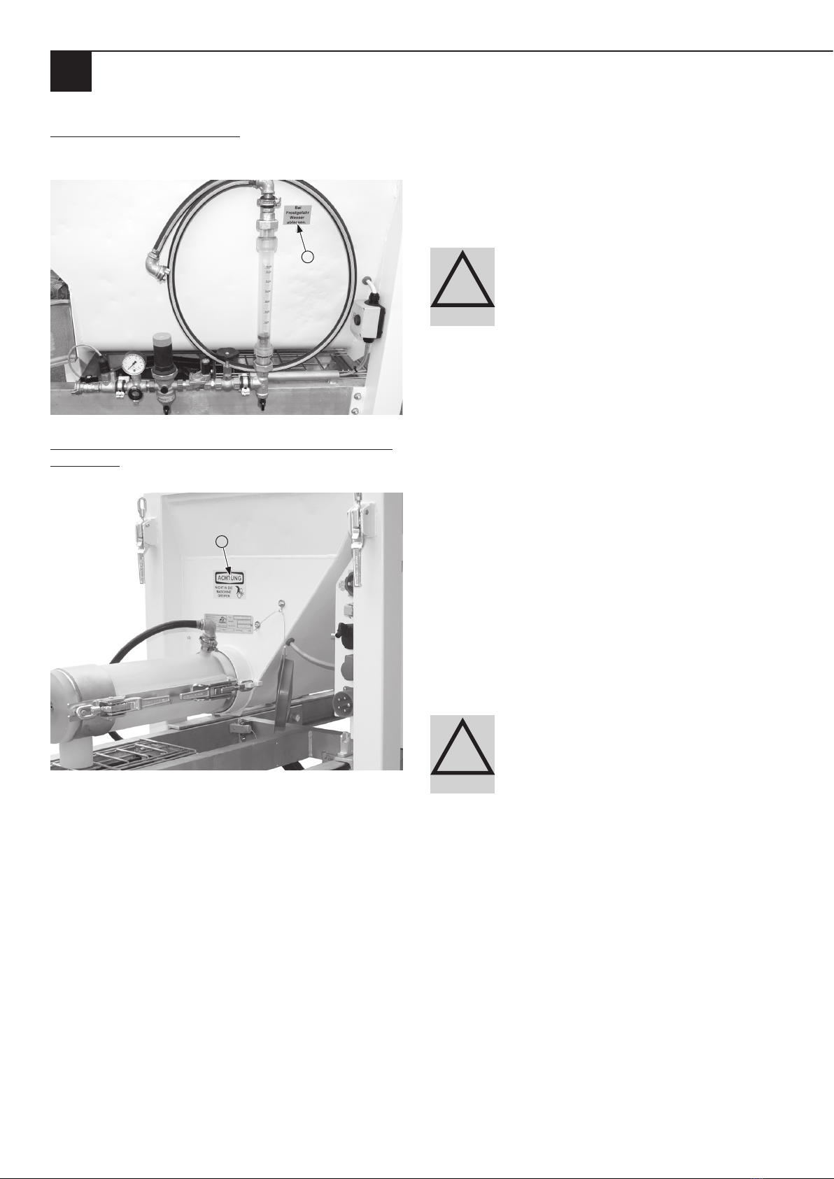
Note on the material hopper (8):
• If there is a risk of frost, drain the water (see water fit-
ting).
8
Note on the material hopper above the type plate or mix-
ing tube (9):
• ATTENTION: Do not reach into the machine.
9
Observe all safety and danger notices attached to the
machine. Always keep the safety and hazard informa-
tion in a legible condition.
2.4 Personnel qualification
INOTECofferstrainingcoursesontheoperationofthesmallsilo
inoCOMB Cabrio. Use INOTEC service for the initial com-
missioning of the machine; this also serves as an opportu-
nity to provide operators with training on how to operate
the mixer.
!
DANGER In case of unqualified operation of the
small silo inoCOMB Cabrio, there is a risk of danger
to life and health of the operating personnel as well
as property damage to the inoCOMB Cabrio or other
assets.
2.5 Responsibility of the operator
• Only use trained or instructed personnel to operate the
inoCOMB Cabrio small solos.
• Define employees’ responsibilities for operating, setting
up, maintaining and servicing the machine clearly.
• Only task untrained staff or individuals who have not re-
ceived any instruction with operating the machine when
there is a trained or instructed specialist available to su-
pervise them.
• Only have work on the electrical control system carried
out by a qualified electrician.
• When using a sprayer, never point it at people or at ob-
jects in danger.
2.6 Personal protective equipment (PPE)
!
CAUTION PPE – particularly gloves, safety boots,
a safety helmet and safety goggles and respiratory
protection – must be used. Even though the small silo
inoCOMB Cabrio does not cause increased noise expo-
sure, we recommend the use of hearing protection on
the construction site.

Page 11
EN
Chapter 3 Technical data
3 Technical data
3.1 Rating plate
1
5
4
23
Item Component Value
1 Manufacturer, address and contact
details, CE marking
-
2 Name and type of machine -
3 Machine’s year of construction -
4 Machine number -
5Technical data
- Voltage
- Current
- Mixer motor power
- Pump motor power
400 V
25 A
4.0 kW
6.3 kW
You must always state the machine number if you would
like to order spare parts, have any queries or would like
to make a complaint. You will find this information on the
rating plate or on the delivery note.
3.2 Electric control system, pump output, particle size,
weight, dimensions
Mains voltage 400 V, 50 Hz
Mains supply line (CEE plug) 32 A (to be supplied
by customer)
Fuse min. 25 A
Delivery rate* 2 to max. approx. 100
l/min
Delivery range* up to 80 m
Delivery height* up to 40 m
to be processed max. 8 mm
Weight (empty) approx. 420 kg
Dimensions:
Length 1,200 mm
Width 800 mm
Height 1,300 mm
* Material-dependent and depending on the consistency of the material –
observe the material manufacturer’s instructions.
3.3 Mortar pressure gauge
Automatic shutdown 40 bar
3.4 Water measuring system
Pressure being too low min. 3 bar at 1,500 l/h
Pressure reducer
ex-works setting
2.5 bar
Solenoid valve 24 V
Supply line ¾ inch water pipe
(to be supplied by
customer)
3.5 Material container
Filling quantity material con-
tainer
approx. 200 l
Filling quantity with attach-
ment bonnet
approx. 1,000 l
3.6 Mixer motor
Power/speed motor 1
Power/speed motor 2
4.0 kW, 280 rpm
4.0 kW, 373 rpm
Installation position Motor horizontal
Electrical data f = 50 Hz, I = 8.6 A,
U = 400 V, IP 55
Insulation class F, ED = S1
Colour White
3.7 Pump motor
Power/speed 6.5 kW, 297 rpm-1
Installation position Motor horizontal
Electrical data f = 100 Hz, I = 14 A,
U = 400 V, IP 55
Insulation class F, ED = S1
Colour White
3.8 Metering shaft
Worm wing maximum height: 20 mm
Minimum height of augur
blades
(wear limit)
13 mm
3.9 Mixing shaft
Maximum height of mixer
blades
57 mm
Minimum height of mixer
blades
(wear limit)
53 mm
3.10 Pump shaft
Maximum height of augur
blades
38 mm
Minimum height of augur
blades
(wear limit)
30 mm

Page 12
EN
Chapter 4 Assembly and function
3.11 Rotor/Stator
Depending on the set select-
ed or area of application
Set “D”: D7-2.5S
Set "Ü1: 1R6
Set “Ü2”: 2R6
Set “RS”: R7 - 1.5
with clamping
strip
3.12 Noise emission
Sound power level LWA 78 dB (A)
3.13 Operating conditions
Temperature range 2 - 45 °C
Relative humidity, maximum 80 %
4 Assembly and function
4.1 Scope of delivery inoCOMB Cabrio
Item no. 10042612
Small silo consisting of:
• Frame
• Material container
• Switching cabinet
• Vibrating unit
Mixing unit consisting of:
• Gear motor 373 rpm
• Water fitting
• PU mixing tube inoPower Mix “S” with wide material
outlet
Pump unit consisting of:
• Extendable feed pump
• Stainless steel pump housing
• Gear motor frequency controlled
• Toolbox
Set “D” Cabrio
for spray applications (22 l / 40 bar)
Item no. 10043990*
Set “Ü1” Cabrio
for industrial screeds (100 l / 15 bar)
Item no. 10043988*
Set “Ü2” Cabrio
for floor levelling compounds (100 l / 30 bar)
Item no. 10043989*
Set “RS” Cabrio
for coarse-grained material (50 l / 15 bar)
Item no. 10043991*
_____________________________
* For scope of delivery, see accessories
4.2 Functionality
The small silo inoCOMB Cabrio is used for mixing and con-
veying pumpable (mineral or organic products) materials up
to approx. 8 mm grain size. Dry mortar, screed material or
floor levelling compounds pre-mixed by the material manu-
facturer can be used. The material hopper of the small silo
can optionally be filled with bagged material, with one-way
containers or with big bags. During operation, the dry ma-
terial is conveyed from the material hopper into the mixing
pipe via the metering shaft. In the mixing tube, the dry ma-
terial − with the addition of water − is mixed with the mix-
ing shaft to form a homogeneous, pasty or liquid product.
At the outer end of the mixing tube, the mixed material falls
directly into the pump hopper. In the pump hopper, the ma-
terial is transported to the pump unit (rotor/stator) via the
pump shaft. The material is pumped from there via the ma-
terial hoses to the processing location. There, it is applied to
walls and ceilings with appropriate spray/adhesive guns or a
reprofiling sprayer or poured directly onto the floor.

Page 13
EN
Chapter 4 Assembly and function
NOTE
Note the optimum assembly sequence.
The small silo is delivered from the factory with an in-
serted pump hopper.
4.3 Sequence of assembly
1. Open the eccentric lock on the base frame below the
water fitting.
2. Unlock the fixing bolt that secures the extendable pump
hopper and pull out the pump hopper.
3. Push the pump shaft into the shaft in the lower area of
the pump hopper and insert it into the Rotex coupling
of the drive shaft.
4. Insert the suction flange into the opening provided on
the pump hopper (1). Place the pump unit (rotor/stator)
(2) on the suction flange and connect the pump unit
to the pump shaft (3). Then fit the assembly (4) (pres-
sure flange with mortar pressure manometer and the
hose coupling) to the pump unit. Fix the two tie rods (5)
to the pressure flange with the corresponding screws.
Connect the plug of the mortar pressure gauge (6) to
the plug connection attached to the base frame.
32 4
561

Page 14
EN
Chapter 4 Assembly and function
5. Unplug the motor (2) from the socket on the side of
the switching cabinet. Unlock the eccentric lock (3)
that connects the motor to the material hopper and
fold the motor away to the side (4).
123 4
6. Push the metering shaft into the round opening in the
lower area of the material hopper.
7. Fold the motor back again and make sure that the me-
tering shaft is connected to the motor via the motor
claw.
8. Lock the eccentric lock that connects the motor to the
material hopper.
9. Insert the plug of the vibrator (1) into the socket pro-
vided and the plug of the motor (2) into the socket
provided on the side of the switching cabinet.
10. Remove the green protective cap from the materi-
al hopper and secure the mixing tube to the material
hopper with the two eccentric locks. Make sure that
the mixing shaft is properly connected to the metering
shaft.
This sectional view shows the connection from the
motor (left) to the metering shaft and from the
metering shaft to the mixing shaft.
4.4 Components
23
45 .1 5
61
4.4.1 Description of the components
Item Component
1 Frame rack with pull-out frame for pump
hopper, material hopper, water supply but-
ton and vibrator
2 Switching cabinet
3 Drive unit for the mixer
4 Water measuring system
5Mixing tube (here in transport position be-
fore assembly)
5.1 Mixing tube intake
6 Drive unit for the feed pump, incl. chain
gear box and pump hopper

Page 15
EN
Chapter 4 Assembly and function
4.4.1.1 Frame with pull-out frame for pump hopper,
material hopper, water supply button and vibrator
The material hopper, the switching cabinet, the drive unit
for the mixer, the pull-out frame for the pump hopper incl.
the drive unit for the pump, the water measuring system
and the water supply button, the vibrator and the mixing
pipe are attached to the frame.
4.4.1.2 Switching cabinet
The switching cabinet is firmly connected to the frame of
the machine. All the necessary connections and controls for
operating the machine are located on the switching cabi-
net.
Connect the feed plug on the switching cabinet to the ex-
ternal power supply (400 V / 50 Hz). The cross-section of
the supply cable is at least 4.0 mm2at 400 V 3 PH! The small
silo inoCOMB Cabrio may only be operated with a permis-
sible RCD type B residual current circuit breaker (30 mA).
Switching cabinet, view from the front
4.4.1.3 Drive unit for the mixer
The mixer motor is firmly connected to the motor plate. For
cleaning purposes or to replace the metering shaft in the
material hopper, the unit can be folded away to the side.
The electrical connection plug of the motor is plugged into
the side of the switching cabinet.
4.4.1.4 Water measuring system
The water measuring system is firmly connected to the
frame of the machine. The connection for the external wa-
ter supply line (min. 3/4") is located on the water measuring
unit. The water supply button is also attached to the frame.
The water flow button and the needle valve are used to
make a rough adjustment of the water supply on the water
flow meter.
4.4.1.5 Mixing tube inoPOWER Mix with mixing shaft
and mixing tube cover
During transport, the mixing tube is dismantled and placed
in the pump hopper. This can be pushed under the material
hopper for transport. The opening for the mixing tube in
the material hopper is closed with a green cover. For opera-
tion, the green cover is removed and the mixing tube is at-
tached to the mixing tube holder with two eccentric locks.
The mixing shaft is pushed into the mixing tube together
with the mixing tube cover and is also fastened to the mix-
ing tube frame with two eccentric locks.
NOTE
Make sure that the mixing shaft is con-
nected to the metering shaft.
4.4.1.6 Drive unit for the feed pump, incl. chain gear
box and pump hopper
The pump motor is firmly connected to the chain gear box
and the pump hopper. The pump hopper contains the pump
shaft, which is connected to the pump unit (rotor/stator). A
level probe is also mounted in the pump hopper to monitor
the level of the material in the pump hopper.
Page 16
EN
Chapter 4 Assembly and function
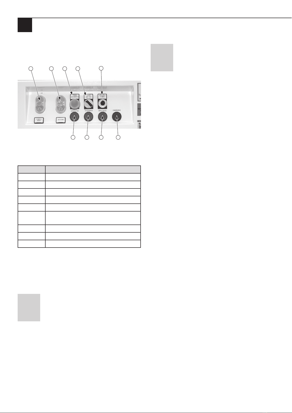
4.5 Displays and controls
4.5.1 Switching cabinet
1 2 3 4 5
6 7 8 9
Switching cabinet, view from the front
Description of the displays, controls and connections
Item Component
1 Pump on/off switch and reset
2 Mixer on/off switch
3 Reverse pump
4 Probe On/Off
5 Pump rotation speed
6 Illuminated button Fault Cover grille Pump
hopper
7 Illuminated button Water pressure fault
8 Illuminated button Mortar pressure fault
9 Illuminated pushbutton Remote control
4.5.1.1 Pump on/off switch and reset
This double pushbutton switches the pump on (I) and off
(0). By pressing the pushbutton on the switching cabinet or
by pressing the remote control switch, the pump switches
on and the button lights up.
NOTE
Functionality with remote control cable
• Remove the cover of the remote control socket for the
remote control cable and plug in the remote control
cable.
• Connect the remote control cable to the material hose
and the air hose of the compressor by means of adhe-
sive tape or cable ties.
NOTE
Working with and without remote control.
• When the remote control cable is plugged into the
switching cabinet, the machine is switched on and off
via the green push button at the end of the remote
control cable.
4.5.1.2 Mixer on/off switch
This double pushbutton switches the mixer on (I) and off
(0). As soon as the mixer is switched on, the pushbutton
lights up.
4.5.1.3 Reverse pump
If this pushbutton is pressed, the pump runs in reverse (e.g.
if a stopper forms in the material hose).
4.5.1.4 Probe On/Off
This switch turns the level probe in the pump hopper on
and off.
4.5.1.5 Pump speed
The pump speed or the desired material flow rate is regulat-
ed with the potentiometer knob.
4.5.1.6 Illuminated button Cover grille
This illuminated button lights up red if the cover grid of the
material hopper is not properly in place. After the fault has
been rectified, the illuminated button flashes and must be
acknowledged once by pressing the button.
4.5.1.7 Illuminated button Water pressure
This button lights up red if the water pressure is below the
minimum pressure of 2.5 bar or if the external water supply
(min. 2.5 bar) is not connected correctly. After the fault has
been rectified, the illuminated button flashes and must be
acknowledged once by pressing the button.
4.5.1.8 Illuminated sensor Mortar pressure
This illuminated button lights up red when the mortar pres-
sure is too high. Switch off the machine immediately if the
delivery pressure exceeds 40 bar. After the fault has been
rectified, the illuminated button flashes and must be ac-
knowledged once by pressing the button.
4.5.1.9 Illuminated button Remote control
This illuminated button lights up when the pump is operat-
ed via remote control. To do this, pull off the cover of the
remote control socket on the left of the switching cabinet
and plug in the remote control connector.
Page 17
EN
Chapter 4 Assembly and function
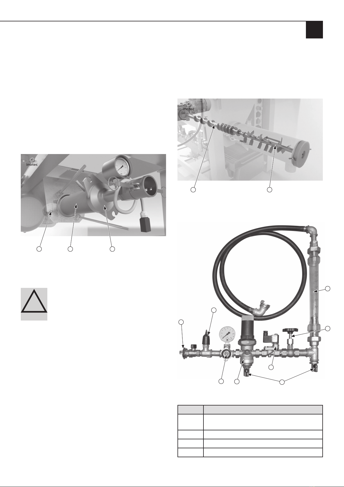
4.5.2 Pump unit (pump motor, pump shaft, rotor/sta-
tor and mortar pressure gauge)
The pump shaft is connected to the pump motor via the
drive shaft and rotates in the pump hopper during oper-
ation. The pump shaft is also connected to the rotor via a
plug-in connection. The assembly with the mortar pressure
gauge and the hose coupling are fixed with two tie rods
mounted on the pump hopper. The pump shaft and the
rotor/stator can be pulled out or dismantled for cleaning
and maintenance. Switch off the machine and disconnect
the mains plug before carrying out this work. The choice of
rotor/stator (see accessories) depends on the planned appli-
cation. The mortar pressure gauge is used to monitor and
display the pressure in the conveyor hose.
12 3
This diagram shows the connection from the pump motor
to the pump shaft, the rotor/stator (2) and the assembly
with the mortar pressure gauge and hose coupling.
!
DANGER Rotating mixing, metering and pump
shafts. Danger of death due to being pulled into the
machine and crushed.
When the motors are running, the metering shaft ro-
tates in the material hopper, the mixing shaft in the
mixing tube and the pump shaft in the pump hopper.
• Do not reach into the rotating mixing or pump shaft.
• Do not bring any objects into the rotating mixing or
pump shaft.
1. Before working on the mixing or pump shaft, disconnect
the external power supply (main switch off). Only loosen
the screw of the protective grids when the machine is
switched off.
2. Pull out the mains plug.
3. Secure the machine against unexpectedly being switched
back on.
4.5.3 Mixing unit (metering shaft and mixing tube
with mixing shaft)
The metering shaft (1) is connected to the mixer motor via
the drive shaft and rotates in the metering hopper during
operation. The mixing shaft (2) in the mixing tube is also
connected to the metering shaft via a plug-in connection.
1 2
4.5.4 Water measuring system
123
4
5
6
8
7
Description of the components in the diagram
Item Component
1Main connection of the external water supply
(min. 2.5 bar water pressure)
2 Pressure reducer
3 Drain cocks
4 Needle valve
Page 18
EN
Chapter 4 Assembly and function
5 Sight glass Water quantity
6 Solenoid valve
7 Cleaning hose connection
8 Water pressure switch
The inlet pressure at the water metering system (min. 2.5
bar) is determined via a water pressure monitor (8). Below
the minimum pressure (2.5 bar), the machine malfunctions
and the illuminated button on the switching cabinet lights
up. After the fault has been rectified, the illuminated button
flashes and must be acknowledged by pressing it once.
4.5.4.1 Installing the water measuring system
1. Connect the supply hose to the external water supply.
2. Open the water valve until a steady water jet comes out
of the hose in order to both clean the water hose of dirt
and ventilate it.
3. Then close the water valve on the external water supply.
4. Connect the external water hose to the GEKA coupling
of the water fitting (1).
5. Close both the water drainage tap (3) below the pres-
sure reducer and the one below the main connection.
6. Connect the internal water hose to the GEKA coupling
of the mixing tube.
!
WARNING Water jet.
Risk of injury and risk of property damage due to es-
caping water.
1. Interrupt the external water supply by closing the water
valve.
2. In order to release the pressure (approx. 2 bar), open
the water drainage valve on the water measuring sys-
tem under the pressure reducer.
3. Remove the hose from the external water supply.
4. Do not point the water jet at other people or yourself.
NOTE
Use an external site compressor for
processing reprofiling mortar.
4.6 Connections
4.6.1 Power connections (230 / 400 V)
5
4
3
2
1
Connections on the switching cabinet left:
CEE appliance plug (400 V) for the central power supply
of the small silo (1), socket (230 V) for connecting an ex-
ternal booster pump (2) if the water pressure is too low
(below 2.5 bar), socket (230 V) for connecting addition-
al appliances (3), remote control socket with cover (4)
and main switch "ON/OFF" (5).
1
2
5
3
4
6
7
8
Connections on the switching cabinet right:
Mounting socket for the level probe in the pump hopper
(1), mounting socket for monitoring the protective grille
(2), mounting socket for monitoring the water pressure and
controlling the solenoid valve (3) on the water measuring
system, socket for the pump motor (4), socket for the mixer
motor (5), socket for the vibrator (6), mounting socket for
the mortar pressure gauge (7) and two unoccupied mount-
ing sockets (8).

Page 19
EN
Chapter 4 Assembly and function
4.6.2 Connections of the water measuring system
1
Connection of the external water supply (1).
4.7 Operating modes
The small silo can be fed with powdery material from bags,
from one-way containers and from big bags.
Material loading of the small silo with bagged material
(high dust generation); room height min. 180 cm.
Material loading of the small silo with big bags via the at-
tachment bonnet (hardly any dust formation); room height
min. 500 cm.
Material loading of the small silo with big bags via two big
bag boxes and the dry conveying unit inoFLEX Duo (low
dust); room height min. 180 cm.
Material loading of the small silo with two one-way con-
tainers (OWC) and the dry conveying unit inoFLEX Duo
(no dust formation); room height min. 180 cm.

Page 20
EN
Chapter 4 Assembly and function
4.8 Accessories
The following accessories can be supplied for the small silo inoCOMB Cabrio.
Set “D”-Cabrio (Rotor/Stator D7-2.5 S)
Ø 89 mm, 22 l/min, 40 bar, e.g., for spray applications
Scope of delivery: Metering shaft - pitch 30 mm, suction flange, pressure flange, mortar
pressure gauge, pump shaft with Rotex coupling, rotor/stator D7-2.5 S, coupling M-part 50
Item no.
10043990 ———P
Optional gear motor 280 rpm for small silo Cabrio
If the small silo is to be used exclusively for processing spray applications such as
reprofiling mortar, the gear motor with 280 rpm can be selected as an option to the
standard drive unit with 373 rpm.
Item no.
10006137 ———P
Set “Ü1”-Cabrio (Rotor/stator 1R6)
Ø = 101 mm, 100 l/min, 15 bar, for e.g. industrial screeds
Scope of delivery: Suction flange, pressure flange, mortar pressure gauge, pump shaft
with Rotex coupling, rotor/stator 1R6, coupling M-part 50 (2" IT), 4 x nut M16,
2 x threaded rods M16 (90 mm), 2 x double nut M1
Item no.
10043988 — — P—
Set “Ü2” Cabrio (Rotor/Stator 2R6)
Ø 101 mm, 100 l/min, 30 bar - for e.g. floor levelling compound
Scope of delivery: Suction flange, pressure flange, mortar pressure gauge, pump shaft
with Rotex coupling, rotor/stator 2R6, coupling M part 50 (2” IT), 2 x eyebolts,
4 x M16 nuts, 2 x M16 threaded rods (270 mm), 2 x M16 double nuts
Item no.
10043989 —P— —
Set “RS” Cabrio (rotor/stator R7-1.5 with clamping bar)
Ø 115 mm, 50 l/min, 15 bar - for e.g. coarse-grained material such as grouted concrete
Scope of delivery: Suction flange, pressure flange, mortar pressure gauge, rotor/stator
R7-1.5 with clamping bar, coupling M-part 50 (2" IT)
Item no.
10043991 P———
Attachment hood for inoCOMB Cabrio for direct filling with big bags
• without cover for filler hole
Item no.
10041543 PPPP
inoFLEX Duo: Two dry delivery units for indirect filling from two
Big-Bag-Box Monos or two one-way containers
The two flexible conveyor shafts transport the material to be processed from two one-way
containers or two big-bag boxes Mono directly into the container of the small silo
Scope of delivery:
Covering hood, 2 flexible delivery shafts, 2 motors, 2 rotary blade sensors
Item no.
10042432 PPPP
Big-Bag-Box Mono
The Big-Bag-Box Mono is filled by means of standard big bags
Scope of delivery: Frame with material container, vibrator (2 pieces), double adapter
230 V for vibrator, threaded connection piece for inoFLEX Mono, connection piece for
industrial hoover
Item no.
10044205 PPPP
Industrial vacuum cleaner KV-3500-EL-LP
Technical data
Operating voltage: 3 x 1.2 kW / 230 V / 50 Hz / 16 A
Filter surface area: 3 m2
Filter class: H
Dimensions: 760 x 600 x 1,570 mm (D x W x H)
Weight: approx. 83 kg
Dust container: Longopac
Scope of delivery: Vacuum, Longopac, 5 m hose Ø 50 mm, suction nozzle, angled suction
pipe, straight suction pipe
Item no.
10043881 PPPP
Set “D”
Set “Ü1”
Set “Ü2”
Set “RS”
Table of contents
Popular Industrial Equipment manuals by other brands

Moog
Moog GAT Rotostat Series operating instructions

KTR-Group
KTR-Group KTR-STOP M-A-F B Series Operating & assembly instructions

SUHNER ABRASIVE
SUHNER ABRASIVE UVC 9-R TRANSLATION OF ORIGINAL INSTRUCTIONS

Festo
Festo ELGA-BS-KF-70 Repair instructions

ABB
ABB HT613228 Operation manual

SCMI
SCMI SUPERSET XL Operation and maintenance


