Shimadzu EI-D1003M User manual

263-13228I
Read the instruction manual thoroughly before you use the product.
Keep this instruction manual for future reference.
Semiconductor Equipment Division
Power Supply Unit for Turbo Molecular Pump
Model:EI-D1003M
Model:EI-D1103M
Model:EI-D1303M
Model:EI-D2003M
Model:EI-D2203M
Model:EI-D2303M
Model:EI-D3203M
Model:EI-D3403M
Model:EI-D4203M
INSTRUCTION MANUAL

Introduction
i
Power Supply Unit
INSTRUCTION MANUAL
Introduction
Thank you for choosing the EI-Dxx03M Power Supply Unit for Turbo Molecular Pump
(hereafter referred to as "power supply unit" or "EI-Dxx03M"). Please read the instruction
manual carefully before using the power supply unit, and save the instruction manual for
future reference.
This instruction manual explains detailed operations of the power supply unit and cables.
For instructions regarding the pump unit, please refer to the instruction manual for the pump
unit to be used.
Standard type is explained in this manual. For special order type, please refer to the out-
lines and constructions of each specification.
Copyrights and Disclaimers
This document is copyrighted by Shimadzu Corporation. Please refrain from reproducing
or copying part or all of this document without permission from Shimadzu.
In an effort to improve the product, this document may be revised in the future without
notice.
Every effort has been made to prepare an accurate and complete manual, but if an error
or omission should be discovered, revisions might not be possible immediately.
Shimadzu does not take responsibility for any effects that may result from the use of this
manual.
Copyright 2003-2006 Shimadzu Corporation.All rights reserved.
©

Precautions for Safe Operation
ii 263-13228
Precautions for Safe Operation
The instruction manual's nomenclature for warnings and precautions complies with
the following safety warning symbols.
WARNING
CAUTION
NOTICE
WARNING
Turbo molecular pump repair and/or power supply repair can be very hazardous.
Only trained technicians who are authorized by Shimadzu may do service of
products.
WARNING
Neither overhaul nor modify the pump proper and power supply unit without
admission. Doing so would impair safety of the pump proper.
WARNING
Decisions on system compatibility should be made by the system designer or the person
deciding the specifications after conducting tests as necessary.The responsibility for
guaranteeing the expected performance and safety of the system lies with the person who
decides system compatibility.
Indicates a potentially hazardous situation whitch, if not avoided, could result
in serious injuly or possibly death.
Indicates a potentially hazardous situation whitch, if not avoided, may result in
minor to moderate injuly or equipment damage.
Emphasizes additional information that is provided to ensure the proper use of
this product.

Introduction
iii
Power Supply Unit
INSTRUCTION MANUAL
CAUTION
The standard power input voltage of the power supply unit EI-Dxx03M (the "xx" number
indicates the model of the corresponding pump) is AC 200 - 240 V ±10%. Connect the power
supply unit to the voltage indicated on the rear panel label only.Connection of the power supply
unit to the incorrect input voltage can cause damage to the equipment. Supply the power via a
breaker (rating 15A).Please provide PE(Protective Earth) connection to the terminal of a "PE"
marked wire in final application.
CAUTION
If an EI-Dxx03M power supply unit is used in combination with an existing pump that was
operated in combination with a power supply unit not having the variable speed function (EI-
xx03MD), the variable speed function cannot be used. (the "xx" number indicates the model of
the corresponding pump.)
If the power supply unit is to be combined with an existing pump, modification and operational
inspections are necessary. Please contact Shimadzu for detailed information.
CAUTION
The following "CAUTIONS" are to prevent operation anomalies.
1.Do not interrupt the electrical power operating the turbo molecular pump while the turbo
molecular pump is in operation.
2.Do not connect or disconnect the turbo molecular pump control cable during the time the
power supply is "ON".
3.Do not operate any equipment (i.e. drill motor, welding machine, etc.) that produces electro-
magnetic pollution, noise, etc., in the immediate proximity of an operating turbo molecular
pumping system (pump, power supply, cables, etc).
4.When using the variable speed function to change the pump rotation rate, use a rotation rate
that does not cause resonance with other devices installed at the site.
iv 263-13228
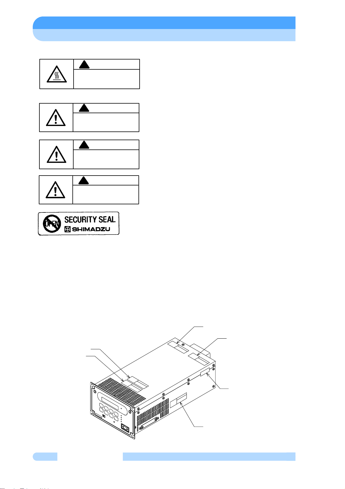
○Explanation of label (1) HOT SURFACE : Risk of burn. (Notes 1)
・Keep off from touching surface of the pump as it is
heated.
・Keep off from touching upper side surface of the
power supply while the pump is in deceleration as it is
heated.
(2) Do not remove cover, or else it may cause some
changes inside and it is failed.
(3) Do not shut off ventilation, or else the inside of
power supply get heated and it is failed.
(4)Besureto usespecifiedcableforthispowersupply.
If not, it may cause connector be broken and power
supply itself failed.
(5) SECURITY seal
This label certificates that the product was made or
maintenanced by Shimadzu or by Shimadzu
authorized facility.
In case "this label is removed" or "there is a mark
showing once this label has been removed",
Shimadzu warranty shall not be applied to the
product.
(Notes 1) The power supply units for some production lots come with a single nameplate, on
which the name is indicated in both English and Japanese, whereas the power supply units
for other production lots come with two nameplates, one in English and one in Japanese.
○Location of label
CAUTION
!
高温注意
HOT SURFACE
Risk of burn. Avoid contact.
やけどのおそれがあります。触らないで下さい。
!CAUTION
DO NOT REMOVE COVER.
ケースを分解しないでください。
!
262-76048
USE SPECIFIED CABLE ONLY.
指定のケーブルを使用してください。
CAUTION
!
262-76050
DO NOT SHUT OFF VENTILATION.
通風口をふさがないでください。
CAUTION
!
262-76049
(3)
(2)
(4)
(1)
(2)
(same on reverse side)
(5)
Introduction
v
Power Supply Unit
INSTRUCTION MANUAL
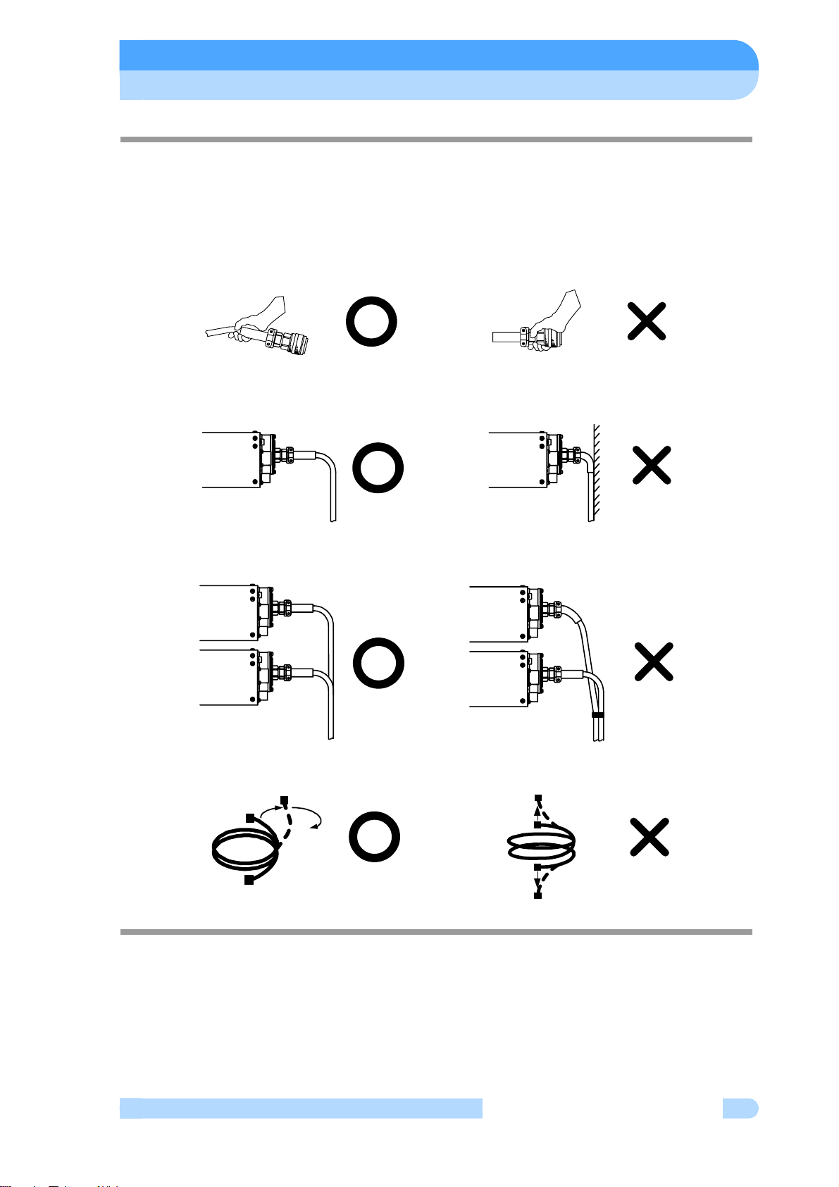
○Installation Precautions
Do not apply abnormal loads to the turbo molecular pump control cable plug and/or connector.
Abnormal loads may cause cable disconnection.
(1) Do not pull the turbo molecular pump control cable by the connector or plug.
(2) When installing the power supply unit into equipment, do not allow any electrical cables to
be in tension or to have very tight bending radii.
(3) Do not bundle the turbo molecular pump control cable with any cables.
(4) Do not twist the turbo molecular pump control cable during connection.

vi 263-13228
○Part Replacement
The lifetime of parts are specified as below.
The request for changing parts exceeding the estimated lifetime should be made to Shimadzu
or an approved service company in order for safety and adequate performance of the pump and
power supply unit. Table 1 Estimated Part Life.
○Warranty period
12 months on new TMP's from the date of shipment from Shimadzu, or from any of its
worldwide sales offices.
○Conditional warranty
During the warranty period and under normal operation, if the TMP fails to meet its product
specification due to defects in material and/or workmanship, Shimadzu will, at its discretion,
either repair it or exchange it with a new one for free.
○Scope of the warranty
The warranty covers only TMPs, controllers and accessories sold by Shimadzu.
○Warranty of repaired or replacement parts
In-warranty repaired or replacement parts are warranted only for the remaining unexpired
portion of the original warranty period applicable to the parts thathave been repaired or replaced.
○Exemption from the warranty
During the warranty period, Shimadzu will charge for repair or exchange in the following cases:
1) Failure caused by natural disasters or fire.
2) Failure or functional deterioration due to the following:
a) Pumping of special gases and materials
b) Ingestion of foreign objects through the TMP's protective net
c) TMP is operated differently than what is prescribed in the instruction manual
d) When Shimadzu determines through failure analysis that the cause of failure was due to
abnormal operation or external circumstances. our engineers judge that the cause of the
trouble is an irregular operation
3) Warranty is voidedif the "Security Seal" on the product has been removed, hampered with,
or altered.
Parts List Estimated Part Life
Transformer 10 years
Electrolytic condenser 5 years
Cooling fan 5 years
Button-type battery 10 years

Introduction
vii
Power Supply Unit
INSTRUCTION MANUAL
○Disposal of Products and Parts
Please contact Shimadzu for proper disposal of its products or parts. There is a possibility to
pollute the environment with the material of the parts, when you dispose this product in an inap-
propriate way.
○LIMITATION OF LIABILITY
EXCEPT AS STATED HEREIN, SHIMADZU MAKES NO WARRANTY, EXPRESSED OR
IMPLIED (EITHER IN FACT OR BY OPERATION OF LAW), STATUTORY OR OTHERWISE:
AND, EXCEPT AS STATED HEREIN, SHIMADZU SHALL HAVE NO LIABILITY FOR
SPECIAL OR CONSEQUENTIAL DAMAGES OF ANY KIND OR FROM ANY CAUSE ARISING
OUT OF THE SALE, INSTALLATION, OR USE OF ANY OF ITS PRODUCTS.

viii 263-13228
This page is intentionally left blank.

Table of contents
ix
Power Supply Unit
INSTRUCTION MANUAL
Table of contents
Introduction
Copyrights and Disclaimers . . . . . . . . . . . . . . . . . . . . . . . . . . . . . . . . i
Precautions for Safe Operation . . . . . . . . . . . . . . . . . . . . . . . . . . . . ii
○Explanation of label . . . . . . . . . . . . . . . . . . . . . . . . . . . . . . . . . . . iv
○Location of label. . . . . . . . . . . . . . . . . . . . . . . . . . . . . . . . . . . . . . iv
○Installation Precautions . . . . . . . . . . . . . . . . . . . . . . . . . . . . . . . . v
○Part Replacement . . . . . . . . . . . . . . . . . . . . . . . . . . . . . . . . . . . . vi
○Warranty period . . . . . . . . . . . . . . . . . . . . . . . . . . . . . . . . . . . . . . vi
○Conditional warranty . . . . . . . . . . . . . . . . . . . . . . . . . . . . . . . . . . vi
○Scope of the warranty . . . . . . . . . . . . . . . . . . . . . . . . . . . . . . . . . vi
○Warranty of repaired or replacement parts . . . . . . . . . . . . . . . . . vi
○Exemption from the warranty. . . . . . . . . . . . . . . . . . . . . . . . . . . . vi
○Disposal of Products and Parts . . . . . . . . . . . . . . . . . . . . . . . . . . vii
○LIMITATION OF LIABILITY . . . . . . . . . . . . . . . . . . . . . . . . . . . . . vii
Table of contents . . . . . . . . . . . . . . . . . . . . . . . . . . . . . . . . . . . . . . . ix
Section 1 OUTLINE AND DESCRIPTIONS
1.1 Outline . . . . . . . . . . . . . . . . . . . . . . . . . . . . . . . . . . . . . . . . . . . 2
1.2 Descriptions. . . . . . . . . . . . . . . . . . . . . . . . . . . . . . . . . . . . . . . 3
1.2.1 Power Supply Unit . . . . . . . . . . . . . . . . . . . . . . . . . . . . . . . . . . . . . . 3
1.2.2 Control Cable. . . . . . . . . . . . . . . . . . . . . . . . . . . . . . . . . . . . . . . . . . 4
1.2.3 Motor Cable . . . . . . . . . . . . . . . . . . . . . . . . . . . . . . . . . . . . . . . . . . . 4
1.2.4 Standard Accessories . . . . . . . . . . . . . . . . . . . . . . . . . . . . . . . . . . 5
Section 2 IDENTIFICATION AND FUNCTION
2.1 Power Supply Unit . . . . . . . . . . . . . . . . . . . . . . . . . . . . . . . . . . 8

Table of contents
x263-13228
Section 3 CONSTRUCTION AND PRINCIPLE
3.1 Power Supply Unit . . . . . . . . . . . . . . . . . . . . . . . . . . . . . . . . . 12
Section 4 SPECIFICATIONS
4.1 Power Supply Unit . . . . . . . . . . . . . . . . . . . . . . . . . . . . . . . . . 14
4.2 Standards Fulfilled . . . . . . . . . . . . . . . . . . . . . . . . . . . . . . . . . 16
Section 5 INSTALLATION
5.1 Installation of the Power Supply Unit . . . . . . . . . . . . . . . . . . . 18
5.1.1 Location of the Power Supply Unit. . . . . . . . . . . . . . . . . . . . . . . . . 18
5.1.2 Installation of the Power Supply Unit . . . . . . . . . . . . . . . . . . . . . . . 18
5.1.3 Compatibility with Previous Models . . . . . . . . . . . . . . . . . . . . . . . . 21
5.2 Connection of Power Cable . . . . . . . . . . . . . . . . . . . . . . . . . . 23
5.3 Connection of the Pump to the Power Supply Unit . . . . . . . . 24
Section 6 OPERATION
6.1 Outline . . . . . . . . . . . . . . . . . . . . . . . . . . . . . . . . . . . . . . . . . . 28
6.1.1 Introduction . . . . . . . . . . . . . . . . . . . . . . . . . . . . . . . . . . . . . . . . . . 28
6.1.2 Operation Flowchart. . . . . . . . . . . . . . . . . . . . . . . . . . . . . . . . . . . . 29
6.2 Start-up Preparation. . . . . . . . . . . . . . . . . . . . . . . . . . . . . . . . 35
6.2.1 Start-up Preparation Sequence in LOCAL Mode. . . . . . . . . . . . . . 35
6.2.2 Start-up Preparation Sequence in REMOTE Mode . . . . . . . . . . . . 35
6.3 Start-up. . . . . . . . . . . . . . . . . . . . . . . . . . . . . . . . . . . . . . . . . . 36
6.3.1 Start-up Sequence in LOCAL Mode . . . . . . . . . . . . . . . . . . . . . . . 36
6.3.2 Start-up Sequence in REMOTE Mode. . . . . . . . . . . . . . . . . . . . . . 36
6.4 Shutting Down . . . . . . . . . . . . . . . . . . . . . . . . . . . . . . . . . . . . 37
6.4.1 Preparations Prior to Shutting Down Operation. . . . . . . . . . . . . . . 37
6.4.2 Shutting Down Sequence in LOCAL Mode . . . . . . . . . . . . . . . . . . 37
6.4.3 Shutting Down Sequence in REMOTE Mode . . . . . . . . . . . . . . . . 38
6.5 Variable Speed Operation . . . . . . . . . . . . . . . . . . . . . . . . . . . 39
6.5.1 Outline . . . . . . . . . . . . . . . . . . . . . . . . . . . . . . . . . . . . . . . . . . . . . . 39
6.5.2 Operation from Start-up to Low Speed Rotation . . . . . . . . . . . . . . 40

Table of contents
xi
Power Supply Unit
INSTRUCTION MANUAL
6.5.3 Operation from Rated Speed Rotation to Low Speed Rotation. . . 41
6.5.4 Operation from Low Speed Rotation to Rated Speed Rotation. . . 41
6.6 Software Operation . . . . . . . . . . . . . . . . . . . . . . . . . . . . . . . . 43
6.7 Remote-Control Connector . . . . . . . . . . . . . . . . . . . . . . . . . . 58
6.7.1 Specifications. . . . . . . . . . . . . . . . . . . . . . . . . . . . . . . . . . . . . . . . . 58
6.7.2 Compatibility with Previous Models . . . . . . . . . . . . . . . . . . . . . . . . 60
6.7.2.1 Replacing the EI-xx03M/MD Power Supply Unit . . . . . . . 60
6.7.2.2 Replacing EI-xx03MZ Power Supply Units. . . . . . . . . . . . 62
Section 7 TROUBLESHOOTING
7.1 Nothing Happens After an Operation is Made. . . . . . . . . . . . 66
7.2 Power Failures. . . . . . . . . . . . . . . . . . . . . . . . . . . . . . . . . . . . 67
7.2.1 Power Failure Counter-Operation . . . . . . . . . . . . . . . . . . . . . . . . . 68
7.3 Vacuum Pressure Rise . . . . . . . . . . . . . . . . . . . . . . . . . . . . . 69
7.4 Abnormal Noise and/or Vibration. . . . . . . . . . . . . . . . . . . . . . 69
7.5 Alarm Detection Capabilities . . . . . . . . . . . . . . . . . . . . . . . . . 69
7.5.1 Movement in Alarm Detection Capabilities (ALARM) . . . . . . . . . . 69
7.5.2 Movement in Alarm Detection Capabilities (WARNING) . . . . . . . . 70
7.5.3 Reset Procedure . . . . . . . . . . . . . . . . . . . . . . . . . . . . . . . . . . . . . . 70
Appendix A COMMUNICATIONS
A.1 GENERAL SPECIFICATION. . . . . . . . . . . . . . . . . . . . . . . . A-2
A.2 INTERFACE SPECIFICATION . . . . . . . . . . . . . . . . . . . . . . A-3
A.2.1 RS-232C . . . . . . . . . . . . . . . . . . . . . . . . . . . . . . . . . . . . . . . . . . . . A-3
A.2.1.1 Transmission Specification. . . . . . . . . . . . . . . . . . . . . . . . A-3
A.2.1.2 Communications Connector. . . . . . . . . . . . . . . . . . . . . . . A-3
A.2.1.3 CABLE . . . . . . . . . . . . . . . . . . . . . . . . . . . . . . . . . . . . . . . A-3
A.2.2 RS-485. . . . . . . . . . . . . . . . . . . . . . . . . . . . . . . . . . . . . . . . . . . . . . A-5
A.2.2.1 Transmission Specification . . . . . . . . . . . . . . . . . . . . . . . A-5
A.2.2.2 Communications Connector. . . . . . . . . . . . . . . . . . . . . . . A-5
A.2.2.3 CABLE . . . . . . . . . . . . . . . . . . . . . . . . . . . . . . . . . . . . . . . A-5
A.3 POWER SUPPLY TO COMPUTER CONNECTION . . . . . . A-7
A.3.1 Communication Cable Connection . . . . . . . . . . . . . . . . . . . . . . . . A-7
A.3.2 Serial Communications Baud Rate Configuration . . . . . . . . . . . . . A-7
A.3.3 RS-485 Multi-drop Settings . . . . . . . . . . . . . . . . . . . . . . . . . . . . . . A-7
A.4 SERIAL COMMUNICATIONS PROTOCOL . . . . . . . . . . . . A-8
A.4.1 Basic Message Structure. . . . . . . . . . . . . . . . . . . . . . . . . . . . . . . . A-8

Table of contents
xii 263-13228
A.4.2 Character to Character Time-out: 0.1 sec. . . . . . . . . . . . . . . . . . . A-8
A.4.3 Command to Answer Time-out: 1 sec.. . . . . . . . . . . . . . . . . . . . . . A-9
A.4.4 Power Supply Command Send Retry Cycles: 5 . . . . . . . . . . . . . . A-9
A.4.5 Command Transmission Specification. . . . . . . . . . . . . . . . . . . . . . A-9
A.4.6 Receiving Sequence . . . . . . . . . . . . . . . . . . . . . . . . . . . . . . . . . . . A-9
A.4.7 Using the Checksum Byte . . . . . . . . . . . . . . . . . . . . . . . . . . . . . . . A-9
A.4.8 Outline of Multi-drop Communications. . . . . . . . . . . . . . . . . . . . . A-10
A.5 TABLE OF COMMANDS . . . . . . . . . . . . . . . . . . . . . . . . . . A-11
A.6 COMMAND DESCRIPTION. . . . . . . . . . . . . . . . . . . . . . . . A-17
A.6.1 Operation Mode . . . . . . . . . . . . . . . . . . . . . . . . . . . . . . . . . . . . . . A-17
A.6.2 Operation . . . . . . . . . . . . . . . . . . . . . . . . . . . . . . . . . . . . . . . . . . . A-18
A.6.3 Run Status . . . . . . . . . . . . . . . . . . . . . . . . . . . . . . . . . . . . . . . . . . A-19
A.6.4 Parameters . . . . . . . . . . . . . . . . . . . . . . . . . . . . . . . . . . . . . . . . . A-20
A.6.5 Events . . . . . . . . . . . . . . . . . . . . . . . . . . . . . . . . . . . . . . . . . . . . . A-20
A.6.6 Timer . . . . . . . . . . . . . . . . . . . . . . . . . . . . . . . . . . . . . . . . . . . . . . A-21
A.6.7 History . . . . . . . . . . . . . . . . . . . . . . . . . . . . . . . . . . . . . . . . . . . . . A-21
A.6.8 Settings . . . . . . . . . . . . . . . . . . . . . . . . . . . . . . . . . . . . . . . . . . . . A-22
A.6.9 Shared Answer . . . . . . . . . . . . . . . . . . . . . . . . . . . . . . . . . . . . . . A-22
A.7 RS-232C COMMANDS / ANSWERS. . . . . . . . . . . . . . . . . A-23
A.8 RELATION OF LOCAL MODE TO REMOTE MODE
OPERATIONS . . . . . . . . . . . . . . . . . . . . . . . . . . . . . . . . . . . . . . A-26
A.9 TROUBLESHOOTING . . . . . . . . . . . . . . . . . . . . . . . . . . . . A-27
A.9.1 No Message can Transmit and Receive . . . . . . . . . . . . . . . . . . . A-27
A.9.2 Sending and Receiving are Done, But Receivable Messages are
Invalid . . . . . . . . . . . . . . . . . . . . . . . . . . . . . . . . . . . . . . . . . . . . . . . . . A-27
A.9.3 Characters Get Disordered from Time to Time, Then Resulting in
CHECKSUM Error. . . . . . . . . . . . . . . . . . . . . . . . . . . . . . . . . . . . . . . . A-27

1
1OUTLINE AND
DESCRIPTIONS
1.1 Outline
1.2 Descriptions
1.2.1 Power Supply Unit
1.2.2 Control Cable
1.2.3 Motor Cable
1.2.4 Standard Accessories

SECTION 1 OUTLINE AND DESCRIPTIONS
2263-13228
11.1 Outline
The turbo molecular pump is a vacuum pump. The turbo molecular pump is used with a
backing vacuum pump to create a high vacuum in a vacuum chamber.
Typical Applications ; Semiconductor equipments,
Industrial equipments,
R&D applications,
The other ultra high vacuum applications.
The turbo molecular pump (one standard set) consists of the following items.
・Pump 1
・Power Supply Unit 1
・Control Cable 1
・Motor Cable 1
・Standard Accessories 1 Set
The cable length must be specified for the magnetic bearing cable and motor cable. (Refer to
Sections 1.2.2 and 1.2.3.)
1.2 Descriptions
3
Power Supply Unit
INSTRUCTION MANUAL
1
1.2 Descriptions
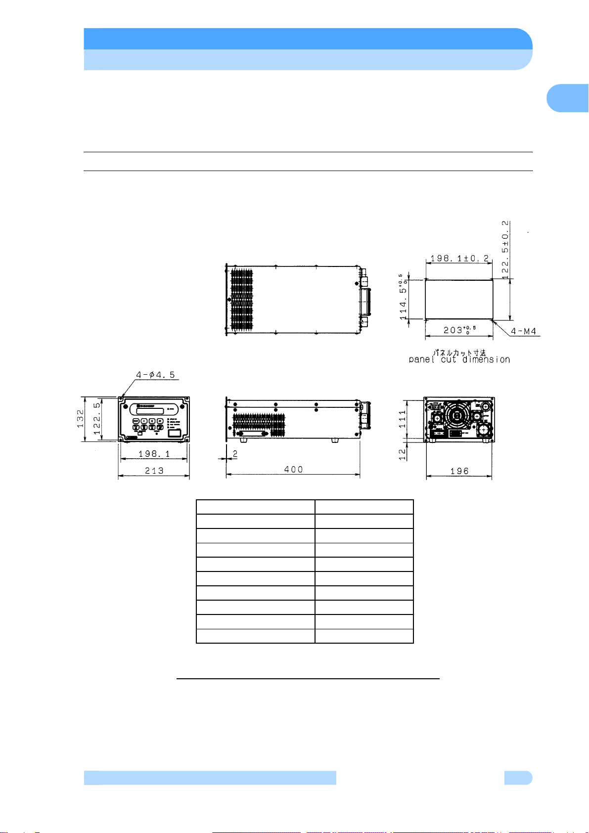
1.2.1 Power Supply Unit
Fig.1-1 Outside Dimensions of Power Supply Unit
Description Parts number
EI-D1003M 262-78689-02
EI-D1103M 262-78690-02
EI-D1303M 262-78688-02
EI-D2003M 262-78691-02
EI-D2203M 262-78692-02
EI-D2303M 262-78693-02
EI-D3203M 262-78685-02
EI-D3403M 262-78694-02
EI-D4203M 262-78696-02

SECTION 1 OUTLINE AND DESCRIPTIONS
4263-13228
11.2.2 Control Cable
The cable can be selected from the following.
1.2.3 Motor Cable
The cable can be selected from the following
Description Note Parts number
Control Cable
3 meters length, straight plugs for both sides.
5 meters length, straight plugs for both sides.
7 meters length, straight plugs for both sides.
10 meters length, straight plugs for both sides.
15 meters length, straight plugs for both sides.
20 meters length, straight plugs for both sides.
30 meters length, straight plugs for both sides.
262-78187-03
262-78187-05
262-78187-07
262-78187-10
262-78187-15
262-78187-20
262-78187-30
Description Note Parts number
Motor Cable
(for Air cooled type and Air cooled chemical type)
3 meters length, straight plugs for both sides.
5 meters length, straight plugs for both sides.
7 meters length, straight plugs for both sides.
10 meters length, straight plugs for both sides.
15 meters length, straight plugs for both sides.
20 meters length, straight plugs for both sides.
30 meters length, straight plugs for both sides.
(for Wide range type and Wide range chemical
type)
3 meters length, straight plugs for both sides.
5 meters length, straight plugs for both sides.
7 meters length, straight plugs for both sides.
10 meters length, straight plugs for both sides.
15 meters length, straight plugs for both sides.
20 meters length, straight plugs for both sides.
30 meters length, straight plugs for both sides.
262-76410-03
262-76410-05
262-76410-07
262-76410-10
262-76410-15
262-76410-20
262-76410-30
262-76409-03
262-76409-05
262-76409-07
262-76409-10
262-76409-15
262-76409-20
262-76409-30

1.2 Descriptions
5
Power Supply Unit
INSTRUCTION MANUAL
1
1.2.4 Standard Accessories
Description Q'ty Notes Parts Number
1Power cable 15meters length 262-76773-05
2Remote Control
Connector 1MR-34MG
MR-34L4 (Pin type connector)
(Connector hood)
070-50791-63
070-50792-75
3 Instruction Manual 1 263-13228

SECTION 1 OUTLINE AND DESCRIPTIONS
6263-13228
1
This page is intentionally left blank.

2
2IDENTIFICATION AND
FUNCTION
2.1 Power Supply Unit
This manual suits for next models
8
Table of contents


