Shineray XY400-A User manual
XY400 –A Maintenance Manual Foreword
1
Foreword
With the ever increasing varieties of motorcycles, new structures and new techniques have increasingly been applied. To
help shineray users and maintenance personnel better understand the maintenance, adjustment and repair techniques of
XY400-A motorcycle, we prepared this maintenance manual. This manual is expected to facilitate the SHINERAY users and
maintenance personnel and provide technical guidance for them.
The masterstroke of the manual is the XY400-A motorcycle , and the contents in Chapter 1-Chapter 3 are applicable to the
adjustment of various parts of the motorcycle. Chapter 4-18 describes various constituting parts of the motorcycle respectively.
Chapter 19 contains the electrical system diagram.
The standard maintenance procedures, maintenance precautions and general maintenance knowledge are not covered in
this manual. Any user or maintenance personnel who needs the above information may refer to the related materials
All materials, charts and various data, as well as performance indices referenced herein, are for the latest model in our product
family at the date this manual is printed. Shineray Co., Ltd. Shall have the right to, at any time, amend this manual without prior
notice. The copyright of all parts of this manual belongs to China shineray Co., Ltd. and no units or individuals are allowed to
reprint it the without consent of our company.
We hope you will enjoy the comfort and pleasure it brings to you during your driving!

XY400 –A Maintenance Manual Contents
2
Contents
1. Overview
1-12
2. Lubrication system
13-20
3. Inspection and adjustment
21-39
4. Fuel system
40-44
5. Removal and installation of engine
45-49
6. Cylinder head, cylinder and piston
50-63
7. Clutch and Right crankcase cover
64-74
8. Magneto and starting system
75-83
9. Crankcase, crankshaft and Shift mechanism
84-99
10. Frame and exhaust system
101-107
11. Front wheel, front overhang and steering stem
108-124
12. Rear wheel and rear overhang
125-135
13. General remarks of electrical system
136-137
14. Power supply system
138-140
15. Starting system
141-144
16. Illumination signal system
145-151
17. Electrical starting control system
152-157
18. Engine management system
158-174
19. Electrical System Diagram
175
Overview
Engine
Vehicle body
Electrical system

XY400-A Maintenance Manual Overview
1
1. Overview
Engine Number Position
Bar Tool
About Motorcycle Maintenance
Maintenance Period Table
Technical Data of Main Performance
Symbol Descriptions
Standard Torque Values
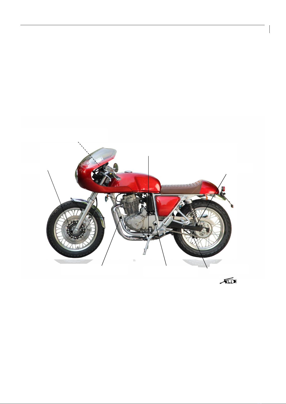
Engine Number Position
Photo of Complete Vehicle:
Frame Number Position:
Engine Number Position:
Frame Number
Engine Number

XY400-A Maintenance Manual Overview
2
Maintenance Precautions
1. Whenever reassembling after being disassembled,
replace new washers, sealing members, etc.
2. While fastening bolts or nuts, proceed in diagonal
crossing sequence to gradually screw down to the
required torque for 2 to 3 tries.
3. After being disassembled, the parts and components
should be cleaned before being inspected and
measured
To clean the spare parts, use only the cleaning fluid that
is incombustible or has high ignition point.
Before reassembling, apply the specified lubricating oil
to the sliding surface of the parts and components.
After reassembling, check whether all the spare parts
are mounted properly by means of turning, moving and
operating them.
4. To disassemble and assemble a motorcycle, special
service tools (SST) and general-purpose tools must be
used in accordance with relevant regulations.
5. The specified or equivalent lubricating grease (oil) must
be applied to or refilled into the specified locations.
6. When 2 or more persons are carrying out the operation,
they shall work with each other and pay attention to
safety.
7. Before operating, always remove the negative (-) end of
the battery first and take care to prevent the wrench or
the like from touching the frame. After operating,
reconfirm all the connections, fixings and junctions. If
the battery is already removed, connect the positive (+)
end first.
XY400-A Maintenance Manual Overview
3
8. In case the fuse is blown, check for the causes and, after
being repaired, replace corresponding fuse as per the
specified capacity.
9. The caps must be securely put on the terminals after the
operation is complete
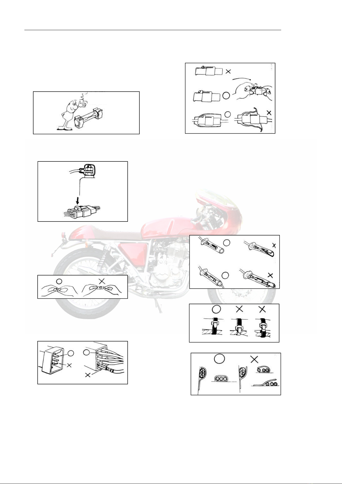
10. While disassembling a connector joints with lock,
release the lock before proceeding with operation.
While disassembling a connector joints, hold the connector
body without pulling the wire harness.
Before connecting the connector, the terminals shall be free
from breaking or bending. Make sure the terminals are not too
long or are falling off.
The connector shall be fully inserted in place.
For a connector with lock, confirm whether the lock is
completely fixed.
Make sure the harness is not falling off
Make sure the plastic jacket of the connector is securely
covering the connector without scaling off.
11. Before connecting a connector, make sure the sleeve is
not broken and the opening of the intermediate terminal
is not too large
The joint shall be fully inserted in place.
Make sure the plastic jacket is housing the terminal
completely. The opening of the plastic jacket shall not face up.
12. The harness fixing strap shall firmly button the specified
position on the frame.
13. The clamp shall reliably bite the wire harness
In case of a welded clamp, it shall not bite the wire harness
Crackle
Confirm capacity!

XY400-A Maintenance Manual Overview
4
towards the weld mark
The wire harness shall be clamped at the position without
contacting a rotating part or a removing element.
The wire harness shall be clamped at the position without
contacting a part that generates high temperature.
The wire harness shall be clamped at the position without
contacting the edge or sharp corners of the vehicle body.
The wire harness shall be incapable of passing through the
position contacting a bolt, a screw head or any front part.
The wire harness shall not be slackened or be forcibly pulled.
If the wire harness has to contact the edge or sharp corner
parts, the contacting part shall be protected with hose or
adhesive tape.
In case of a wire harness with garland, it shall be reliably
harnessed.
Do not damage the garnish of the wire harness.
Once the wire harness is damaged, repair it by coiling with
plastic adhesive tape.
While mounting parts and components, do not press the wire
harness.
Do not mount wire harness with it twisted.
14. When wiring, note when turning it leftwards or
rightwards to the limit position, the wire harness shall not
be tightened up or slackened, and make sure there is no
significant bending, pressing, intervening of marginal
parts.
15. While using the test table, operate according to the
maintenance manual after understanding the
explanations in the instruction manual.
16. Do not drop or throw the parts and components.
Do not touch!
Pay attention not to press it.
Do not pull!

XY400-A Maintenance Manual Overview
5
17. In case of rust on the terminals, carry out connection
operation after disposing it with abrasive paper, etc.
18. Do not forcibly twist or forcefully bend the cable.
Because a deformed or damaged cable is the cause of
bad operation and damage.
Have you learned by heart the method of
application? Are the measurement range
and polarity in accordance with the
instruction manual?
Rust must be
eliminated!
XY400-A Maintenance Manual Overview
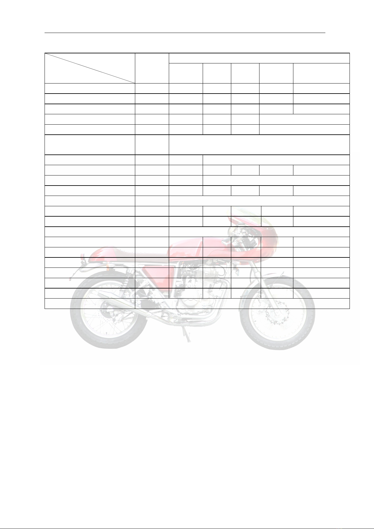
6
Technical Data of Main Performance
Item
Data
Dimension & Weight
Length
Width
Height
Wheelbase
Min. ground clearance
Complete vehicle weight
2105mm
760mm
1130mm
1420mm
160mm
Non-loaded weight: 155kg, Curb weight: 160kg,
Vehicle body
Frame type
Rake angle
Front suspension device
Rear suspension device
Front Tire size
Rear Tire size
Front wheel pressure
Rear wheel pressure
Front brake
Rear brake
Fuel tank volume
Fuel grade
Cradle type
28°
spring & hydraulic composite damping
spring & hydraulic composite damping
100/90-19
130/70-18
Normally loaded: 225 kPa,
Normally loaded: 225 kPa,
Single disc type ModelΦ276
Drum brake ModelΦ160
13L
93#
Engine
Mode
Cylinder bore × Stroke
Cylinder displacement
Compression ratio
Max. power
Max. torque
Valve clearance (cold)
Valve driving gear
Air filter
Cooling method
Lubrication method
Engine oil grade
Engine oil charge volume
Engine oil filter element
Electric motor starting
Idle speed
Net weight of engine
Single-cylinder Oil –cooling 4-stroke engine
85.0mm ×70.0mm
397.2cc
8.8:1
19.5kw/7000rpm
30.0N.m/5500rpm
IN: 0.07-0.10
EX: 0.08-0.12
Chain drive
Oilpaper filter
Oil-cooling
Pressure / Splash
15W/40-SF (summer )and 10W/30-SF(winter)
2.2L
Oilpaper filter
Electric / foot start
1500±50r/min
40kg
XY400-A Maintenance Manual Overview
7
Driving system
Clutch
Clutch operating system
Variable speed gear
Primary reduction ratio
Transmission gear ratio
Final reduction ratio
Gear shifting mode
Wet clutch, coil clutch, paper friction wafer
Manual mechanical
5-speed constant mesh
2.666
Ⅰ 2.615
Ⅱ 1.789
Ⅲ 1.350
Ⅳ 1.120
V 0.892
2.533
Left foot operated to and back type
Sequence: I-N-Ⅱ-Ⅲ-Ⅳ-V
Electrical system
Electric generator
Accumulator capacity
Power supply system
Fusible cutout
Spark plug
Spark plug gap
Ignition coil type
Fuel supply mode
Ignition mode
Ignition advance angle
Ignition timing
Front lamp
Turn lamp
Stop / Rear-position lamp
Permanent magnet DC magneto
12V9A.h
DC power supply, and the electric generator is only used to
recharge the accumulator
15A/10A
DPR8Z
0.6-0.7mm
Open magnetic circuit
Electronically injection, ECU control
EMS
EMS
EMS
12V/55W/60W
Front: 12V10W Rear: 12V10W
12V1.5W/0.5W
XY400-A Maintenance Manual Overview
8
Standard Torque Values
ENGINE
Item
Quantity
Thread diameter
(mm)
Torque value (N.m)
Thread locker
Cylinder head cover connecting bolt
13
8
8~12
Cylinder bolt
4
10
40~50
2
6
8~12
Valve adjusting screw nut
4
10
8~12
Timing driven sprocket bolt
2
7
7~11
Rocker-arm shaft cover
2
14
24~28
Magneto flywheel fastening nut
1
12
38~45
LOCTITE 243
Clutch fastening nut
1
18
114~126
LOCTITE 243
Primary driving gear fastening nut
1
18
143~157
LOCTITE 243
Oil drain plug
1
12
28~32
Crankshaft, main-shaft bearing baffle screw
5
6
8~12
LOCTITE 648
Stud
1
6
8~12
Stud
4
10
40~50
Exhaust valve stud bolt
2
8
10~14
LOCTITE 243
Stator connecting bolt
3
6
8~12
LOCTITE 648
Stator leads pressure plate bolt
2
6
8~12
LOCTITE 648
Spark Plug
1
12
18~25
Pensioner plate fastening bolt
1
6
7~10
Vehicle body
Item
Quantity
Thread diameter
(mm)
Torque value (N.m)
Thread locker
Front wheel spindle
1
14
50~60
Front vibration damper plate
1
10
30~40
Real wheel spindle nut
1
16
60~90
Rear fork shaft nut
1
14
50~60
Engine hanging bolt
3
10
30~40
4
8
20~30
Steering handle set bolt
4
8
20~30
Front fork vertical pipe cap nut
1
22
60~90
Lower connection plate set bolt
2
10
30~40
Upper connection plate set bolt
2
6
8~12
Rear sprocket nut
6
8
20~30
LOCTITE 243
Brake disc fastening nut
8
8
20~30
LOCTITE 243
Speed signal panel screw
4
8
20~30
LOCTITE 243
Front brake caliper screw
2
8
20~30
LOCTITE 243
In addition to the torque values of the important parts as listed above, the torque values for other standard fasteners
are as follow:
XY400-A Maintenance Manual Overview
9
Name and dimensions
Torque value (N.m)
5mm bolt & nut
4.5 ~6
6mm bolt & nut
8~12
8mm bolt & nut
18 ~25
10mm bolt & nut
30 ~40
12mm bolt & nut
50 ~60
5mm Screw
3.5 ~5
6mm Screw
7~11
6mm spool bolt & nut
10 ~14
8mm spool bolt & nut
20 ~30
10mm spool bolt & nut
30 ~40
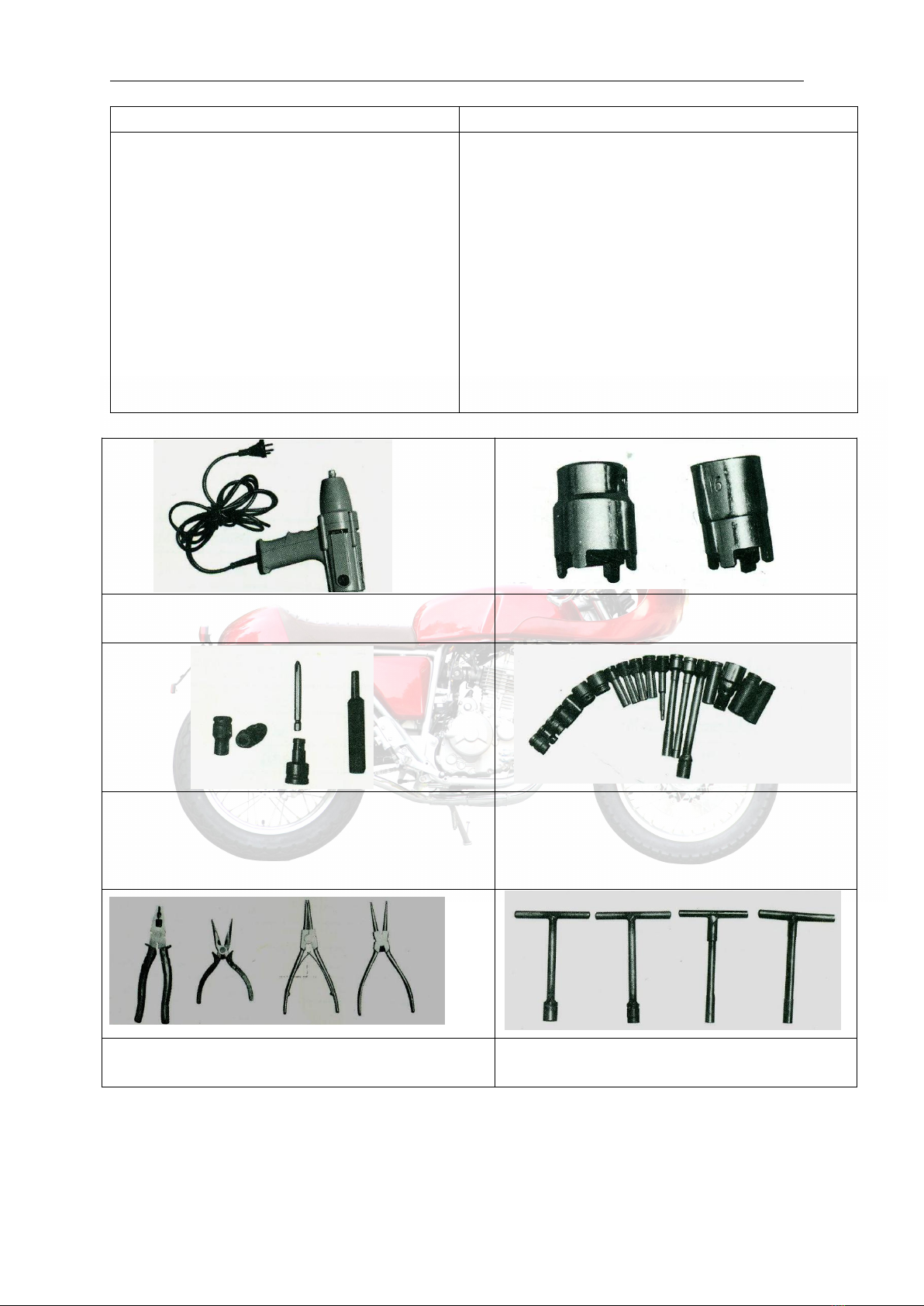
Bar Tool
Motorized gun: special power tool for mantling/ dismantling
bolt and nut
Pawl socket: for mantling/dismantling oil filtering
element nut and clutch nut
A and B bolt socket: for mantling/dismantling A and B bolt and
exhaust muffler bolt
Adaptor: electric special tool for cross,hexagon gun tip
Valve adjusting socket: for valve clearance adjustment
Socket: for mantling/dismantling nuts and bolts
Cutting plier, Nipper plier, expansion plier: for mantling/
dismantling flexible retainer
T-socket wrench
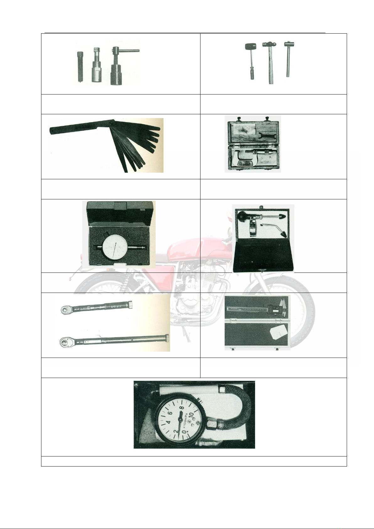
XY400-A Maintenance Manual Overview
10
Magnetic generator rotor puller: for dismantling magnetic
generator rotor
Rubber hanner, Iron hammer, Copper hammer
Feeler gauge: to measure the clearance of piston, cylinder,
valve, etc.
Micrometer: to measure the dimensions of piston,
piston pin, etc.
Dial gauge: to measure the wheel bouncing, cylinder inner
diameter, etc.
Cylinder barometer: to measure the cylinder pressure
Wrench: measure tightness of ad bolt
Vernia caliper: measure size of rear wheel hub internal
diameter
Tire barometer: to measure the tire pressure
XY400-A Maintenance Manual Overview
11
Maintenance Period Table
Maintenance times
Maintenance Items
Period
Odometer km (Remark 2)
1000
k m
4,000
km
8,000
km
12,000
km
Remarks
* Fuel system passage
I
I
I
* Throttle operating system
I
I
I
I
* Throttle valve body
I
I
I
I
Air filter element
Remark 1
C
C
Replace every 12,000km driving
Spark Plug
I
I
Replace every 12000km driving
Engine lubricant oil
For a motorcycle, change every 1000km, and then change it every
2000km driving
Oil filter
R
Replace every 12,000km driving
* Tensioner
Remark 3
I
I
I
I
Both intake and exhaust
Remark 3
I
Check every 4,000km driving
Clutch
I
I
I
I
*Driving chain
Proceed with I and L for every 500km driving
**Front and rear brake system
I
I
I
I
** Brake Pad
I
I
I
I
** Brake fluid
Change every 2 years
*Front and rear brake lamp switch
I
I
I
I
*Accumulator
Monthly
I
I
I
I
*Suspension system
I
I
I
I
*Nut and bolt fastening
I
I
I
I
** Wheel & tire
I
I
I
I
** Steering column bearing
I
I
I
I
** Steering backstay cable
Inspect every 5000km driving and replace every 10000km driving
Maintenance shall be carried out to the motorcycle in a specified period. The meanings of various symbols in the list are as
follows: I:Carry out inspection, cleaning, adjustment, lubrication or replacement.
C: Cleaning. R: Replacement. A: Adjustment. L: Lubrication.
* This item is subject to maintenance by persons from SHINERAY Service Station. If the user has special service tools,
maintenance accessories or maintenance ability, it can repair it by itself.
** To ensure safety, this item is only subject to maintenance by persons from SHINERAY Service Station.
Remarks:
①While driving in a dusty area, it shall be cleaned more often.
②When the odometer reads more than the given maximum value, its maintenance period shall still repeat as per the
mile interval as stipulated in the table.
③To ensure safety, the adjustment of timing chain and valve clearance shall only be carried out by persons from
SHINERAY Service Station.

XY400-A Maintenance Manual Overview
12
Symbol Descriptions
Meanings of various symbols in this manual:
Each time reassembled after being removed and disassembled, it must be replaced with a new
one.
Use special service tools (SST)
Use general-purpose tools.
Tightening torque of 50 N.m.
Use suggested engine oil.
Use the mixtures of engine oil and molybdenum disulfide
Use thread locker.
Use sealant.
Use lithium base grease.
Measures to be prompted during operating, inspecting and maintaining.
Special instructions or disposal measures given to prevent motorcycle from being damaged.
Special instructions or measures given to avoid serious damages or personal injuries.
Explanation
NOTICE:
WARNING:

XY400-A Maintenance Manual Lubrication system
13
2. Lubrication system
Maintenance notice
Inspection of lubricating oil
Troubleshooting
Replacement of lubricating oil
Lubricating Position of Complete Vehicle
Cleaning of Lubricating Oil Strainer
Lubrication of Control Lines
Cleaning and Replacement of Lubricating Oil Filter
Engine Lubrication System Diagram
Oil Pump
Maintenance notice
This section introduces the inspection and replacement method of engine lubricating oil as well as the cleaning method of
lubricating oil strainer and lubricating oil filter. It also introduces various lubricating positions of the complete vehicle of this model.
As an important factor that influences the engine’s performance and life span, the lubricating oil must be selected as per
regulations; ordinary engine oil, gear oil, vegetable oil, etc. are not allowed to be used instead of it. This engine was filled with
gasoline engine oil of 10W/40EG grade when leaving factory for sale. If you want to use other lubricating oil, its quality scale must
reach Grade SG, and its viscosity shall be selected according to the accompanying diagram depending upon region and air
temperature changes. While replacing lubricating oil, fully discharge the original lubricating oil in the crankcase and clean it up
with washing kerosene, and then refill fresh lubricating oil as per regulations.
The lubricating oil inside the engine must be fully discharged before inspection and cleaning.
Technical specifications: Lubricating oil charge volume: 1.8L
Oil pump flow rate: 10L/min (when engine speed is at 4000 rpm).
Tightening torque of oil drain plug:28-32N.m
WARNING:
Repeatedly contacting the engine lubricating oil for a long period may cause skin cancer. Although such possibility is
small when you deal with used engines oil every day, Care must be taken to fully cleanse your hands with soap
and water after dealing with the used engine oil. Children are strictly prohibited from getting near to it
。
Selecting viscosity as per temperature conditions
Low temperature property
�Fuel economical efficiency
�Lubricat ing property under high temperature
High temperature property
�Low temperature starting
property
�Noise reduction property under high
temperature
XY400-A Maintenance Manual Lubrication system
14
Troubleshooting
Lubricating Position of Complete Vehicle
Among the positions shown in the above diagram, besides applying dedicated lubricating oil for chain
to the
driving chain, apply lithium base grease to all other positions.
All lubricating oils not specified for use in this manual shall be ordinary common lubricating oil.
All sliding surfaces and cables not shown in this diagram shall be coated with lubricating oil or lubricating grease.
Lubrication of Control Lines
Regular lubrication shall be carried out to the clutch control line, throttle control line and steering cable. To do this, remove the
upper joining parts of all control lines, sufficiently lubricate and maintain their hoisting cables and all points of support with lithium
base grease.
●Lubricating oil contaminated
1. Fail to replace lubricating oil according to the
maintenance period table;
2. The pouring orifice thread is damaged thus causing
poor seal;
3. The piston ring is worn.
●Lubricating oil pressure low
1. The oil level is too low;
2. Oil through, orifice port or oil strainer is clogged;
3. Oil pumps failure.
●Lubricating oil consumes too fast
1. There is leakage with the engine;
2. The piston ring is worn.
3. The inlet/exhaust valve guide is worn;
4. The oil shield is worn or damaged.
Front wheel bearing
Rear wheel bearing
Engine lower hanging bolt
Rear fork shaft lever
Side stand shaft
Driving chain
Upper/lower retainers of vertical pipe
XY400-A Maintenance Manual Lubrication system
15
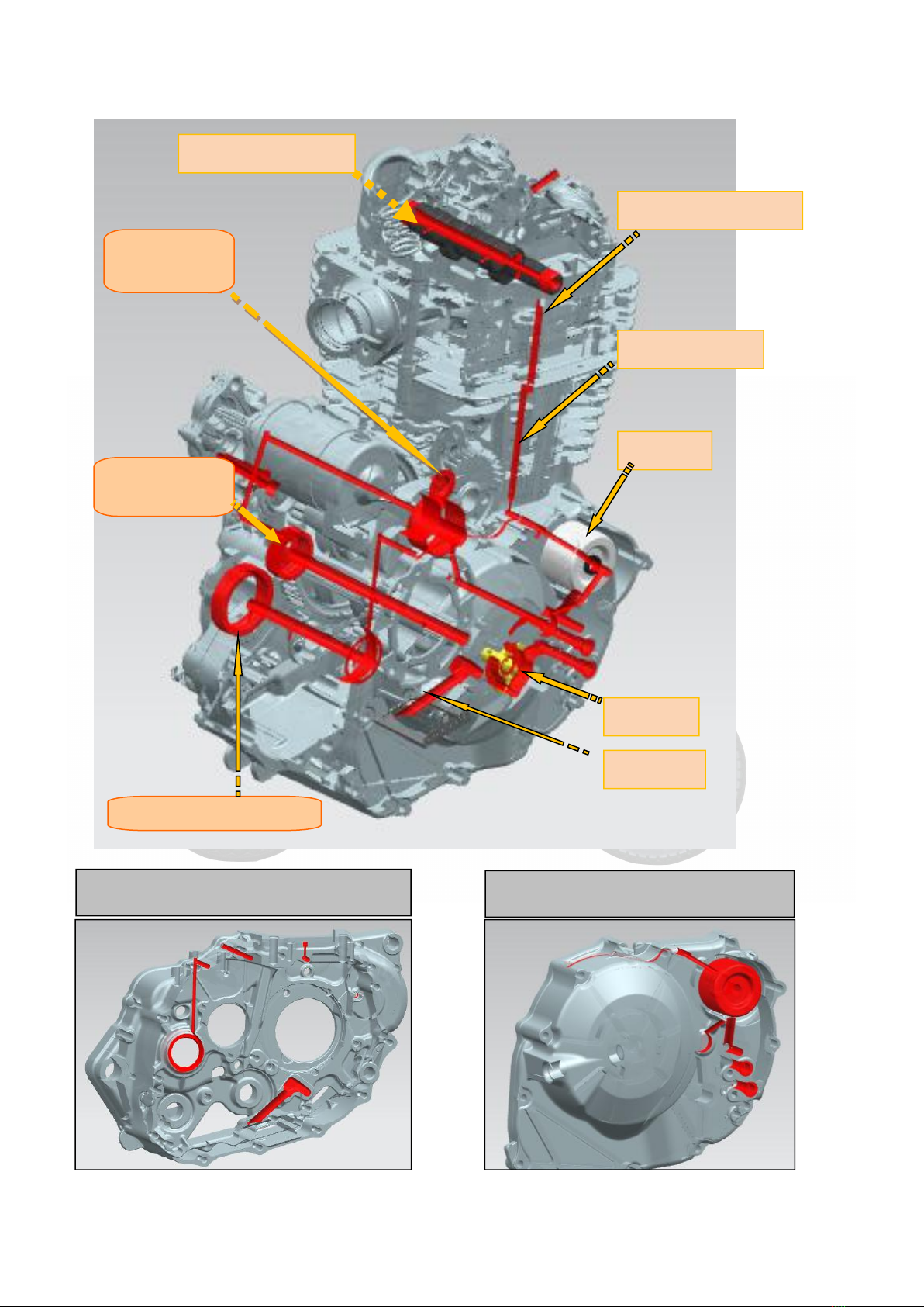
Engine Lubrication System Diagram
Right crankcase body oil through
Right crankcase cover oil through
Crankshaft oil
through
Spindle oil
through
Countershaft oil through
Cylinder head oil through
Cylinder oil through
Oil filter
Camshaft
Oil pump
Oil strainer

XY400-A Maintenance Manual Lubrication system
16
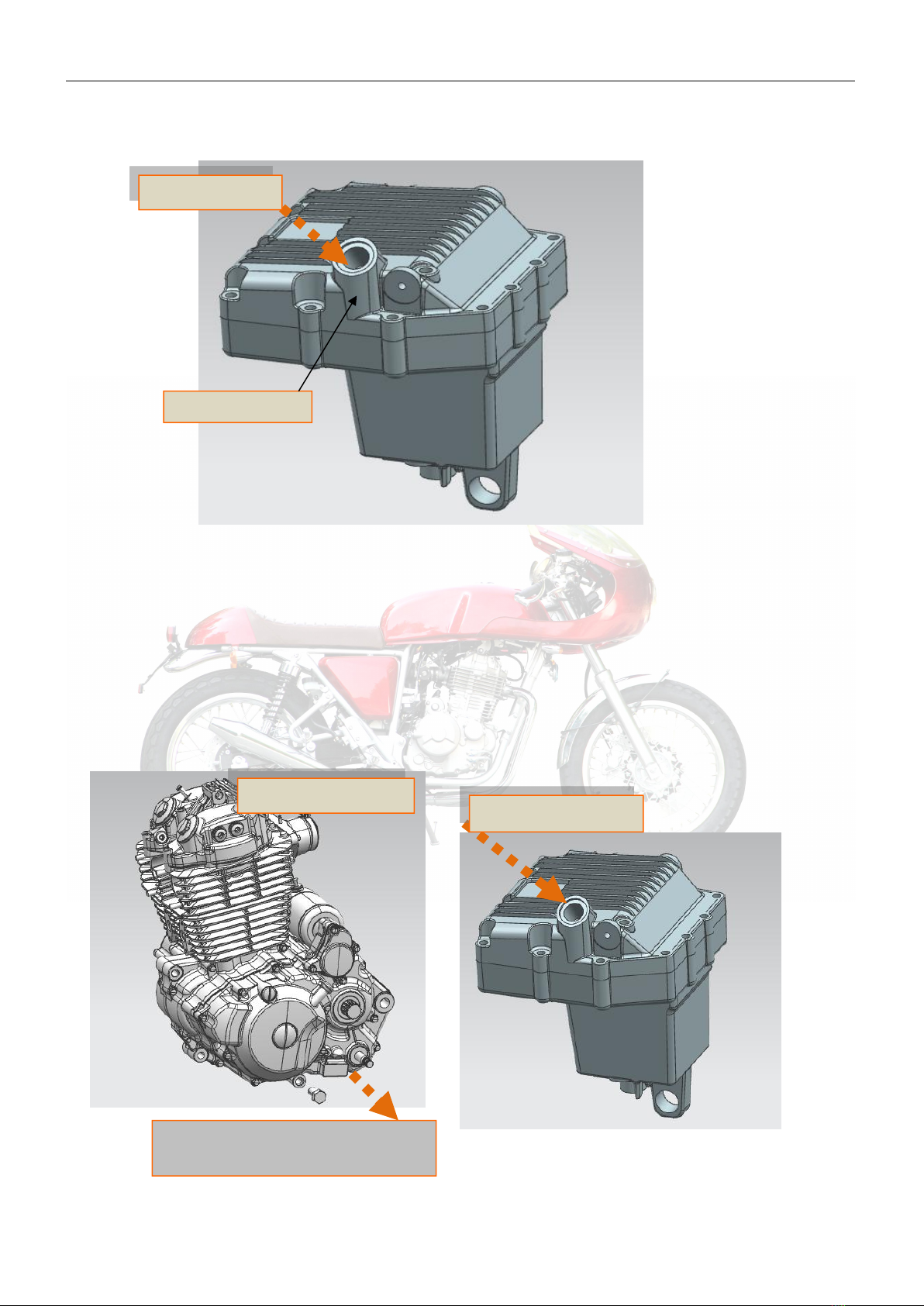
Inspection of lubricating oil
Park the motorcycle on a flat surface,look over the engine oil dipstick on the oil pot,if the engine oil level is under the lower scale
line, refill the recommended lubricating oil until the oil level reaches the upper-middle limit。
Left crankcase body oil through
Cylinder block, cylinder head, camshaft bearing seat and a
camshaft oil through
Upper scale line
Engine oil level is between the upper
and lower scale lines
Lower scale line
Inspection of lubricating oil
XY400-A Maintenance Manual Lubrication system
17
Refilling method: Remove the oil filler plug, refill the engine oil slowly with a funnel until the oil level in the engine oil dipstick
reaches the upper-middle limit. Then insert the oil filter plug and screw it up.
Replacement of lubricating oil
While replacing lubricating oil, it shall be carried out before the engine has cooled down. This will ensure quick and complete
discharge of the engine oil inside the crankcase.
When replacing, unscrew the oil drain plug and discharge the waste engine oil, and then clean the oil drain plug, engine oil
strainer, engine oil filter, etc. Finally, insert the oil drain plug. Unscrew the oil filter plug and slowly refill 1.8L new engine oil of the
specified trademark into the crankcase, then insert the oil filter plug.
Lubricating oil
Lubricating oil
Waste engine oil flow into the oil collector
Lubricating oil draining
Lubricating oil refilling
XY400-A Maintenance Manual Lubrication system
18
CAUTION
Application of engine oil of poor quality will have an impact on the functional performance and life span of the
motorcycle engine.
Cleaning of Lubricating Oil Strainer
It shall be carried out while replacing lubricating oil.
While cleaning, you should unscrew the oil drain plug to drain the waste engine oil, and flush the strainer with cleaning agent;
place the motorcycle side down to facilitate cleaning as required. Then insert the oil drain plug, and proceed with the remaining
steps according to the method of “Replacement of Lubricating Oil".
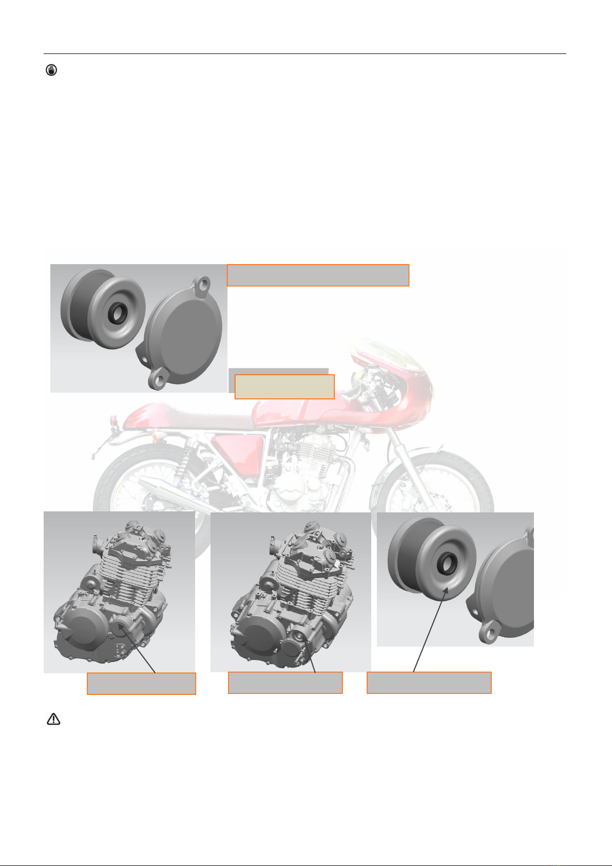
Cleaning and Replacement of Lubricating Oil Filter
Remove the engine oil filter cover to detach the engine oil filter element, clean the filter cover and filter element with cleaning
agent, and then mount the clean engine oil element. Replace with a new one as required.
Check for damage of the engine oil filter cover and its O-shaped sealing ring; replace with a new one as required.
Mount the engine oil filter cover and screw up the bolt to the specified torque.
Notice
Before the crankcase is refilled with fresh engine oil, the engine oil filter must be cleaned.
Flush the strainer with cleaning agent
Cleaning
Remove oil filter
Replacement of Filter
Cleaning of Strainer
Table of contents
Other Shineray Motorcycle manuals


