6H15-019 Rev.3
Issued : Jul. 2015
Revised : Apr. 2019
Calibration material JIS SCM440 flat surface 1. Calibration material
MODEL FK-602F Transducers are calibrated for JIS SCM440 flat
surface (more than 54 mm dia.).
If the measured target is other than JIS SCM440 flat surface, it will
present a different characteristics. In such a case, calibration by the
connected equipment (e.g. monitor) side should be required for
system operation.
2. Shield wire connection
Connect shield wire of signal cable (3-wire shielded cable between
driver and monitor) to driver’s “COM” terminal (Spring lock terminal:
“Shield” terminal) and monitor’s “COM” terminal.
If this is not adhered to, noise may be caused.
3. Connector isolation, etc.
The connector connecting the sensor cable and the extension cable
shall be insulated with the attached insulation sleeve (transparent
shrink tube) or fluoro resin insulation tape.
The vinyl-insulating tape shall not be used.
4. Megger test of signal cable
If megger test is made on the signal cable (3-wire shielded cable), be
sure to discharge the charged electric load before connecting the
cable to driver.
If this caution is not adhered the driver could be dameged.
5. Sensor installation
Not available for rain water at out door use.
It may cause the sensitivity change and insulation down.
6. Calibrated as a system
The sensor, extension cable and driver, which are calibrated as a
system, shall be connected with each serial No. as specified in the
inspection test report. If this is not adhered the output characteristics
may be out of specification.
7. Linearity
The linearity margin provides for examination result in our factory. This
regulated value is not applied to the examination result in the site.
8. The instructions manual contains important information such as
conditions necessary for safe handling of the system.
Such information and conditions are important and indispensable for
ensuring safety. Therefore, be sure to read the instructions manual
thoroughly before handling the system.
9. Cable length 5.0m sensor is designed for 5m system only.
Can not use for 9m system.
Measuring range 0.5 mm to 6.5 mm from sensor tip
Sensitivit
*1 2.5 V/mm
Sensitivit
erro
*1 Within ±4 %
Linearit
*1 Within ±70
m of 2.5 V/mm straight line :
(if calibrated as a system)
Within ±90
m of 2.5 V/mm straight line :
(including interchangeability errors)
Linear range : 6 mm
Frequency responce*1 DC to 10 kHz or more (-3 dB)
Max. output voltage*1 Approx. -23 VDC
Sensor abnormal output
volta
e*1 Approx. -0.6 VDC (Sensor OPEN/Sensor SHORT)
Output impedance*1 50 ΩCurrent 5 mA (max.)
Current consumption
10 kΩload
Max. -15 mA
Output noise*1 Approx. 20 mVpk-pk + power supply noise
Sensor tip diamete
Approx. 18 mm dia.
Cable diamete
Approx. 3.6 mm dia.
Connector diamete
Approx. 7.1 mm dia.
System cable length 5 m or 9 m
Sensor cable color Blue
Extension cable color Black
Operating temperature
range
Senso
: -40 to +125 °C
Extension cable : -40 to +125 °C
Driver : -40 to +80 °C
Temperature characteristic
(Temperature drift)
Senso
: Less than ±3 % of F.S.
Extension cable : Less than ±3 % of F.S.
Condition : Gap=5 mm, Target : JIS SCM440
0 to 80 °C (at 20 °C standard)
Driver : Less than ±3 % of F.S.
Loop : Less than ±4 % of F.S.
Condition : Gap=5 mm, Target : JIS SCM440
0 to 60 °C (at 20 °C standard)
Operating humidity range 30 to 95 % RH (non-condensing, non-submerged)
(Sensor body : 100 % RH)
Power suppl
-24 VDC ±10 %
Dielectric strength of drive
Between each terminal and mounting plate :
1 mA or less at 500 VAC for one minute
Insulation resistance of
drive
Between each terminal and mounting plate :
100 MΩor more at 500 VDC
Applicable wire Screw type terminal block (M4) : 0.75 to 2mm2
Size Spring lock terminal : 0.2 to 1.5mm2
Driver mass Approx. 200 g
Oil leakage reduction
performance*2
Even if oil is poured in to the cable with the
pressure of 0.05MPa. Oil does not leak from
opposite the cable for 7 days.
(cable length : 4m, at 25 °C)
*1 The above specification apply at 25 °C with -24 VDC power supply and
load resistance 10 kΩand JIS SCM440 target (thickness≥5 mm).
*2 Oil leaka
e reduction performance is applied to the extension cable part.
Specifications Notice
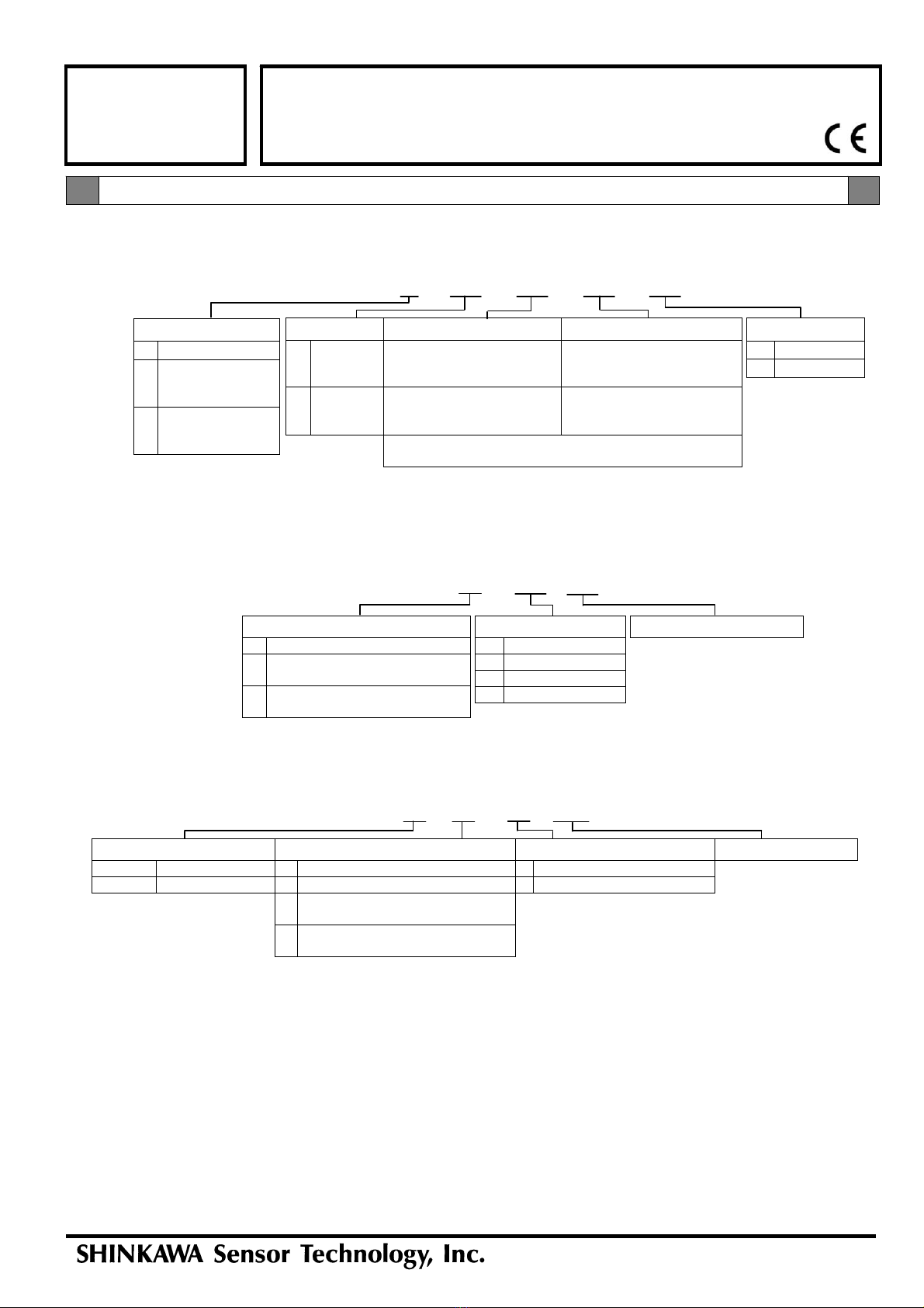
Configuration
FK-602F Transducer
Oil leakage reduction extension cable option
Page 1 of 2
FK Series
Transducer
Specifications
Connector
Sensor Extension cable*2
(Oil leakage reduction)
Driver
System cable length
FK-602F1 : 5m
FK-602F2 : 9m