Shinko AER-101-ORP User manual

Digital Indicating ORP Meter
AER-101-ORP
Instruction Manual
2
Preface
Thank you for purchasing our AER-101-ORP, Digital Indicating ORP Meter.
This manual contains instructions for the mounting, functions, operations and notes when
operating the AER-101-ORP. To ensure safe and correct use, thoroughly read and
understand this manual before using this instrument.
To prevent accidents arising from the misuse of this instrument, please ensure the operator
receives this manual.
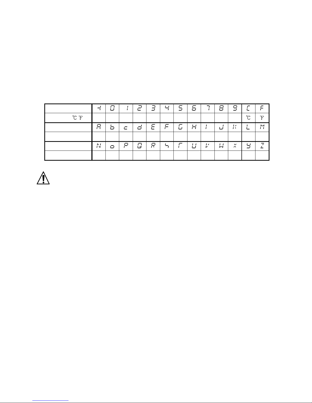
Characters Used in This Manual
Indication
Number, / -1 0 1 2 3 4 5 6 7 8 9
Indication
Alphabet A B C D E F G H I J K L M
Indication
Alphabet N O P Q R S T U V W X Y Z
Caution
• This instrument should be used in accordance with the specifications described in the manual.
If it is not used according to the specifications, it may malfunction or cause a fire.
• Be sure to follow all of the warnings, cautions and notices. If they are not observed, serious
injury or malfunction may occur.
• The contents of this instruction manual are subject to change without notice.
• Care has been taken to assure that the contents of this instruction manual are correct, but if
there are any doubts, mistakes or questions, please inform our sales department.
• This instrument is designed to be installed through a control panel. If it is not, measures
must be taken to ensure that the operator cannot touch power terminals or other high
voltage sections.
• Any unauthorized transfer or copying of this document, in part or in whole, is prohibited.
• Shinko Technos Co., Ltd. is not liable for any damage or secondary damage(s) incurred as
a result of using this product, including any indirect damage.

21
Safety Precautions (Be sure to read these precautions before using our products.)
The safety precautions are classified into 2 categories: “Warning” and “Caution”.
Depending on the circumstances, procedures indicated by Caution may result in
serious consequences, so be sure to follow the directions for usage.
Warning
Warning
• To prevent an electrical shock or fire, only Shinko or other qualified service personnel
may handle the inner assembly.
• To prevent an electrical shock, fire or damage to the instrument, parts replacement may
only be undertaken by Shinko or other qualified service personnel.
SAFETY PRECAUTIONS
• To ensure safe and correct use, thoroughly read and understand this manual before
using this instrument.
• This instrument is intended to be used for industrial machinery, machine tools and
measuring equipment. Verify correct usage after purpose-of-use consultation with our
agency or main office. (Never use this instrument for medical purposes with which
human lives are involved.)
• External protection devices such as protective equipment against excessive
temperature rise, etc. must be installed, as malfunction of this product could result in
serious damage to the system or injury to personnel. Also proper periodic maintenance
is required.
• This instrument must be used under the conditions and environment described in this
manual. Shinko Technos Co., Ltd. does not accept liability for any injury, loss of life or
damage occurring due to the instrument being used under conditions not otherwise
stated in this manual.
Caution with respect to Export Trade Control Ordinance
To avoid this instrument from being used as a component in, or as being utilized in the
manufacture of weapons of mass destruction (i.e. military applications, military
equipment, etc.), please investigate the end users and the final use of this instrument. In
the case of resale, ensure that this instrument is not illegally exported.
Caution
Procedures which may lead to dangerous conditions and cause
death or serious injury, if not carried out properly.
Procedures which may lead to dangerous conditions and cause
superficial to medium injury or physical damage or may degrade
or damage the product, if not carried out properly.

4
1. Installation Precautions
Caution
This instrument is intended to be used under the following environmental conditions
(IEC61010-1): Overvoltage category , Pollution degree 2
Ensure the mounting location corresponds to the following conditions:
• A minimum of dust, and an absence of corrosive gases
• No flammable, explosive gases
• No mechanical vibrations or shocks
• No exposure to direct sunlight, an ambient temperature of 0 to 50 (32 to 122 ) that
does not change rapidly, and no icing
• An ambient non-condensing humidity of 35 to 85%RH
• No large capacity electromagnetic switches or cables through which large current is
flowing.
• No water, oil or chemicals or where the vapors of these substances can come into
direct contact with the unit
• If the AER-101-ORP is mounted through the face of a control panel, the ambient
temperature of the unit – not the ambient temperature of the control panel – must be
kept to under 50 . Otherwise the life of electronic parts (especially electrolytic
capacitors) of the unit will be shortened.
Note: Do not install this instrument on or near flammable material even though the case of
this instrument is made of flame-resistant resin.
2. Wiring Precautions
Caution
• Do not leave wire remnants in the instrument, as they could cause a fire or a
malfunction.
• Use a solderless terminal with an insulation sleeve in which the M3 screw fits when
wiring the AER-101-ORP.
• The terminal block of this instrument is designed to be wired from the left side. The
lead wire must be inserted from the left side of the terminal, and fastened with the
terminal screw.
• Tighten the terminal screw using the specified torque. If excessive force is applied to
the screw when tightening, the terminal screw may be damaged.
• This instrument does not have a built-in power switch, circuit breaker and fuse. It is
necessary to install a power switch, circuit breaker and fuse near the instrument.
(Recommended fuse: Time-lag fuse, rated voltage 250 V AC, rated current 2 A)
• For a 24V AC/DC power source, do not confuse polarity when using direct current (DC).
• Be sure to connect the ground terminal to earth for safety (D-class grounding).
Keep the grounding of this unit separate from other electrical devices, such as motors.
• Do not apply a commercial power source to the sensor which is connected to the input
terminal nor allow the power source to come into contact with the sensor.
• Use the ORP Combined Electrode Sensor in accordance with the sensor input
specifications of the AER-101-ORP.
• Keep the input wires and power line separate.

5
Note about the ORP Combined Electrode Sensor Cable
The ORP Combined Electrode Sensor cable is a highly-insulated (electrical) cable.
Please handle it with utmost care as follows.
• Do not allow terminals and socket of the ORP Combined Electrode Sensor cable to
come in contact with moisture or oil of any kind. Likewise, ensure fingers are clean,
otherwise the insulation will deteriorate, resulting in unstable indication.
Be sure to keep the cable dry and clean at all times.
If the cable is stained, clean it with alcohol, and dry it completely.
• For calibration or electrode checking/replacement, the ORP Combined Electrode
Sensor cable should be wired with sufficient length.
• Keep the ORP Combined Electrode Sensor cable and junction cable away from
electrical devices, such as motors or their power lines from which inductive interference
emanates.
Connection
The ORP Combined Electrode Sensor cable has the following terminals.
Symbol Terminal
M Metal electrode terminal
R Reference electrode terminal
3. Operation and Maintenance Precautions
Caution
• Do not touch live terminals. This may cause an electrical shock or problems in
operation.
• Turn the power supply to the instrument OFF when retightening the terminal or
cleaning.
Working on or touching the terminal with the power switched ON may result in severe
injury or death due to electrical shock.
• Use a soft, dry cloth when cleaning the instrument.
(Alcohol based substances may tarnish or deface the unit.)
• As the display section is vulnerable, do not strike or scratch it with a hard object or put
pressure on it.

6
Contents
1. Model Page
1.1 Model ---------------------------------------------------------------------------------- 8
1.2 How to Read the Model Label -------------------------------------------------- 8
2. Names and Functions of Sections ----------------------------------------------- 9
3. Mounting to the Control Panel
3.1 Site Selection -------------------------------------------------------------------- 10
3.2 External Dimensions (Scale: mm) ------------------------------------------- 10
3.3 Panel Cutout (Scale: mm) ----------------------------------------------------- 11
3.4 Mounting and Removal -------------------------------------------------------- 12
4. Wiring ------------------------------------------------------------------------------------- 13
4.1 Lead Wire Solderless Terminal ------------------------------------------------ 14
4.2 Terminal Arrangement ----------------------------------------------------------- 15
5. Outline of Key Operation and Setting Groups
5.1 Outline of Key Operation -------------------------------------------------------- 16
5.2 Setting Groups --------------------------------------------------------------------- 16
6. Key Operation Flowchart ----------------------------------------------------------- 18
7. Setup
7.1 Turn the Power Supply to the AER-101-ORP ON ------------------------ 21
7.2 ORP Input Function Group ----------------------------------------------------- 22
7.3 EVT1 Action Group --------------------------------------------------------------- 23
7.4 EVT2 Action Group --------------------------------------------------------------- 29
7.5 EVT3 Action Group --------------------------------------------------------------- 35
7.6 EVT4 Action Group --------------------------------------------------------------- 41
7.7 Special Function Group ---------------------------------------------------------- 47
8. Calibration
8.1 Adjustment Mode ----------------------------------------------------------------- 52
8.2 Span Sensitivity Correction Mode -------------------------------------------- 53
8.3 Transmission Output Adjustment Mode ------------------------------------- 54
9. Measurement
9.1 Starting Measurement ----------------------------------------------------------- 55
9.2 EVT1 to EVT4 Outputs ---------------------------------------------------------- 56
9.3 Setting EVT1 to EVT4 Values ------------------------------------------------- 58
9.4 Cleansing Ouput ------------------------------------------------------------------ 59
9.5 Manual Cleansing Mode -------------------------------------------------------- 60
9.6 ORP Input Error Alarm ---------------------------------------------------------- 61
9.7 Cycle Automatic Variable Function ------------------------------------------- 62
9.8 Transmission Output ------------------------------------------------------------- 63

7
10. Specifications
10.1 Standard Specifications ------------------------------------------------------- 64
10.2 Optional Specifications -------------------------------------------------------- 71
11. Troubleshooting
11.1 Indication -------------------------------------------------------------------------- 72
11.2 Key Operation -------------------------------------------------------------------- 73
12 Character Tables
12.1 Setting Group List --------------------------------------------------------------- 74
12.2 Adjustment Mode ---------------------------------------------------------------- 74
12.3 Span Sensitivity Correction Mode ------------------------------------------- 74
12.4 Transmission Output Adjustment Mode ----------------------------------- 74
12.5 Simple Setting Mode ----------------------------------------------------------- 74
12.6 ORP Input Function Group ---------------------------------------------------- 75
12.7 EVT1 Action Group ------------------------------------------------------------- 75
12.8 EVT2 Action Group ------------------------------------------------------------- 77
12.9 EVT3 Action Group ------------------------------------------------------------- 78
12.10 EVT4 Action Group ----------------------------------------------------------- 80
12.11 Special Function Group ------------------------------------------------------ 81

8
1. Model
1.1 Model
A E R - 1 0 1 ORP ,
Input Points 1 1 point
Input ORP ORP Combined Electrode Sensor
Supply Voltage 100 to 240 V AC (standard)
1 24 V AC/DC (*)
Option C5 Serial communication RS-485
EVT3 EVT3, EVT4 Outputs (Contact outputs 3, 4)
(*) Supply voltage 100 to 240 V AC is standard.
When ordering 24 V AC/DC, enter “1” after the input code.
1.2 How to Read the Model Label
The model label is attached to the left side of the case.
(Fig. 1.2-1)
Model, Option
Input indication
Supply voltage, Power consumption
Serial number
Manufacturer
Factory ID
RoHS directive compliant

9
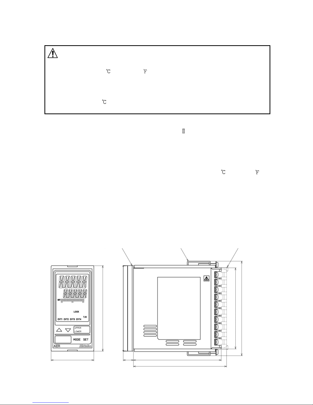
2. Names and Functions of Sections
(Fig. 2-1)
Displays
ORP
Display
ORP value or characters in setting mode are indicated in red/green/orange.
Indications differ depending on the selections in [Backlight selection
(p.49)] and [ORP color (p.49)].
Setting
Display
Values in setting modes are indicated in green.
Indications differ depending on the selections in [Backlight selection
(p.49)] and [Setting Display indication (p.50)].
Output
Display
Backlight green
The bar graph is lit corresponding to the transmission output.
Indications differ depending on the selections in [Bar graph indication(p.50)].
Action Indicators: Backlight orange
EVT1 Lit when EVT1 output (Contact output 1) is ON.
EVT2 Lit when EVT2 output (Contact output 2) is ON.
EVT3 Lit when EVT3 output (Contact output 3) (EVT3 option) is ON.
EVT4 Lit when EVT4 output (Contact output 4) (EVT3 option) is ON.
T/R Lit during Serial communication (C5 option) TX output (transmitting).
LOCK Lit when Lock 1, 2 or 3 is selected.
Unit label
UPPER Attach the user’s unit of ORP Display from the included unit labels if necessary.
LOWER Attach the user’s unit of Setting Display from the included unit labels
if necessary.
Keys
UP key Increases the numeric value.
DOWN key Decreases the numeric value.
MODE key Selects a group.
SET key Switches the setting modes, and registers the set value.
ORP Display
Setting Display
Action Indicators
UP Key
DOWN Key
MODE Key
SET Key
Output Display
Unit label
10
3. Mounting to the Control Panel
3.1 Site Selection
Caution
Use within the following temperature and humidity ranges:
Temperature: 0 to 50 (32 to 122 ) (No icing)
Humidity: 35 to 85 %RH (Non-condensing)
If AER-101-ORP is mounted through the face of a control panel, the ambient
temperature of the unit – not the ambient temperature of the control panel – must
be kept to under 50 , otherwise the life of electronic parts (especially electrolytic
capacitors) of the unit will be shortened.
This instrument is intended to be used under the following environmental
conditions (IEC61010-1): Overvoltage category , Pollution degree 2
Ensure the mounting location corresponds to the following conditions:
• A minimum of dust, and an absence of corrosive gases
• No flammable, explosive gases
• No mechanical vibrations or shocks
• No exposure to direct sunlight, an ambient temperature of 0 to 50 (32 to 122 )
that does not change rapidly
• An ambient non-condensing humidity of 35 to 85 %RH
• No large capacity electromagnetic switches or cables through which large current
is flowing
• No water, oil or chemicals or where the vapors of these substances can come into
direct contact with the unit
3.2 External Dimensions (Scale: mm)
(Fig. 3.2-1)
11.5
104.5 (when terminal cover is used)
98.5
106.2
91
Gasket
Screw type mounting bracket Terminal cover (sold separately)
48
96

11
3.3 Panel Cutout (Scale: mm)
Caution
If lateral close mounting is used for the unit, IP66 specification (Drip-proof/Dust-proof)
may be compromised, and all warranties will be invalidated.
Lateral close mounting
n: Number of units mounted
(Fig. 3.3-1)
130
92+0.8
0
45+0.5
0
n×48-3 +0.5
0
92+0.8
0
12
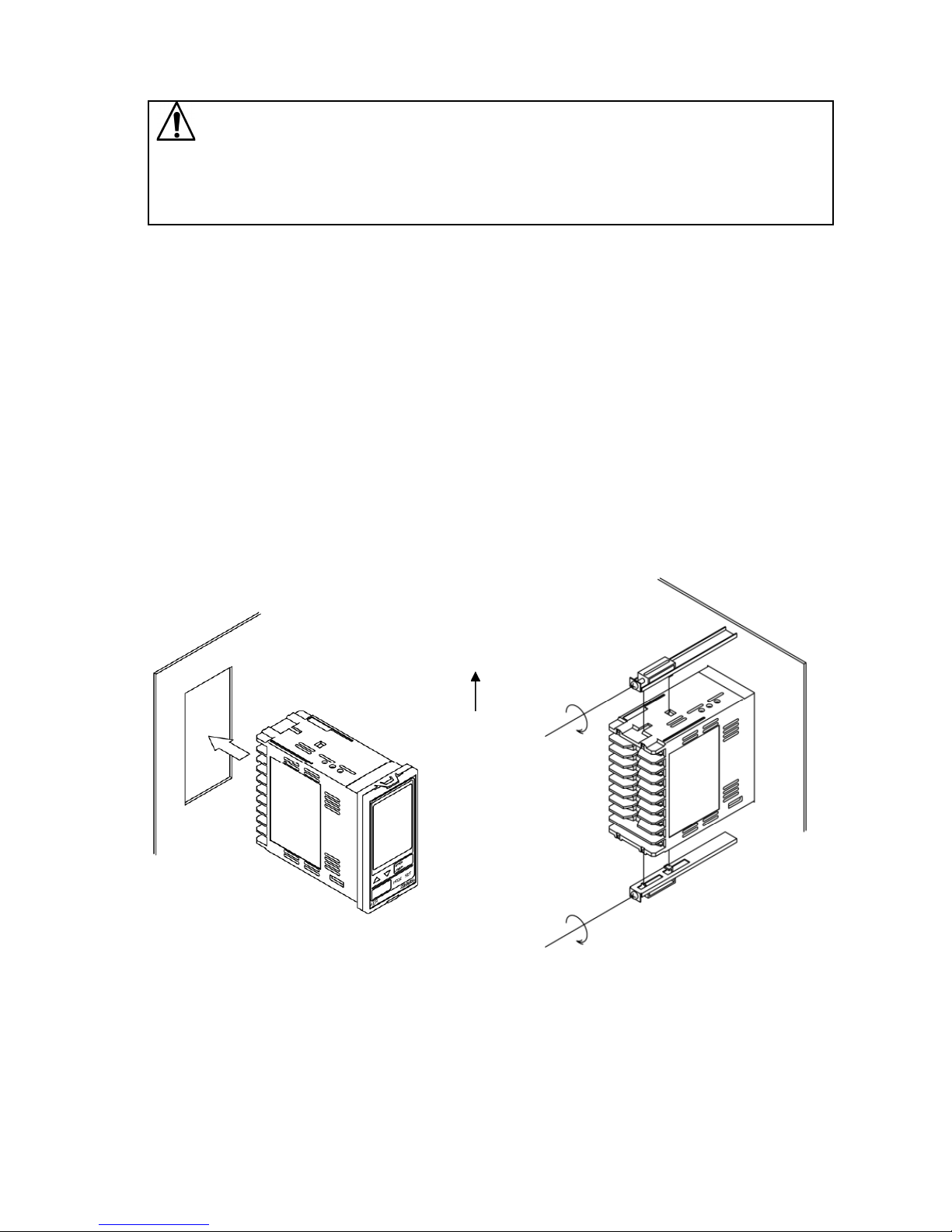
3.4 Mounting and Removal
Caution
As the case is made of resin, do not use excessive force while screwing in
the mounting bracket, or the case or mounting brackets could be damaged.
The tightening torque should be 0.12 N•m.
How to mount the unit
Mount the unit vertically to the flat, rigid panel to ensure it adheres to the Drip-proof/
Dust-proof specification (IP66).
Mountable panel thickness: 1 to 8 mm
(1) Insert the unit from the front side of the panel.
(2) Attach the mounting brackets by the holes at the top and bottom of the case, and
secure the unit in place with the screws.
How to remove the unit
(1) Turn the power to the unit OFF, and disconnect all wires before removing the unit.
(2) Loosen the screws of the mounting brackets, and remove the mounting brackets.
(3) Pull the unit out from the front of the panel.
(Fig. 3.4-1)
UP

13
4. Wiring
Warning
Turn the power supply to the instrument off before wiring or checking.
Working on or touching the terminal with the power switched on may result in
severe injury or death due to electrical shock.
Caution
• Do not leave wire remnants in the instrument, as they could cause a fire or a
malfunction.
• Use a solderless terminal with an insulation sleeve in which the M3 screw fits when
wiring the AER-101-ORP.
• The terminal block of this instrument is designed to be wired from the left side. The
lead wire must be inserted from the left side of the terminal, and fastened with the
terminal screw.
• Tighten the terminal screw using the specified torque. If excessive force is applied to
the screw when tightening, the terminal screw may be damaged.
• This instrument does not have a built-in power switch, circuit breaker and fuse. It is
necessary to install a power switch, circuit breaker and fuse near the instrument.
(Recommended fuse: Time-lag fuse, rated voltage 250 V AC, rated current 2 A)
• For a 24 V AC/DC power source, do not confuse polarity when using direct current
(DC).
• Be sure to connect the ground terminal to earth for safety (D-class grounding).
Keep the grounding of this unit separate from other electrical devices, such as motors.
• Do not apply a commercial power source to the sensor which is connected to the input
terminal nor allow the power source to come into contact with the sensor.
• Use the ORP Combined Electrode Sensor in accordance with the sensor input
specifications of the AER-101-ORP.
• Keep the input wires and power line separate.

14
Note about the ORP Combined Electrode Sensor Cable
The ORP Combined Electrode Sensor cable is a highly-insulated (electrical) cable.
Please handle it with utmost care as follows.
• Do not allow terminals and socket of the ORP Combined Electrode Sensor cable to
come in contact with moisture or oil of any kind. Likewise, ensure fingers are clean,
otherwise the insulation will deteriorate, resulting in unstable indication.
Be sure to keep the cable dry and clean at all times.
If the cable is stained, clean it with alcohol, and dry it completely.
• For calibration or electrode checking/replacement, the ORP Combined Electrode
Sensor cable should be wired with sufficient length.
• Keep the ORP Combined Electrode Sensor cable and junction cable away from
electrical devices, such as motors or their power lines from which inductive interference
emanates.
Connection
The ORP Combined Electrode Sensor cable has the following terminals.
Symbol Terminal
M Metal electrode terminal
R Reference electrode terminal
4.1 Lead Wire Solderless Terminal
Use a solderless terminal with an insulation sleeve in which an M3 screw fits as follows.
The tightening torque should be 0.63 N•m.
Solderless
Terminal Manufacturer Model Tightening
Torque
Y-type Nichifu Terminal Industries CO.,LTD. TMEV1.25Y-3
0.63 N•m
Japan Solderless Terminal MFG CO.,LTD. VD1.25-B3A
Ring-type Nichifu Terminal Industries CO.,LTD. TMEV1.25-3
Japan Solderless Terminal MFG CO.,LTD. V1.25-3
(Fig. 4.1-1)
5.8 mm
max.
3.2 mm 3.2 mm
5.8 mm
max.

15
4.2 Terminal Arrangement
(Fig. 4.2-1)
GND Ground
POWER SUPPLY 100 to 240 V AC or 24 V AC/DC (when 1 is added after the
model)
For 24 V DC, ensure polarity is correct.
EVT1 EVT1 output (Contact output 1)
EVT2 EVT2 output (Contact output 2)
TRANSMIT OUTPUT Transmission output
M, R Electrode sensor
RS-485 Serial communication RS-485 (C5 option)
2 connectors are wired internally.
Use the included wire harnesses C5J and C0J.
EVT3 EVT3 output (Contact output 3) (EVT3 option)
Use the included wire harness HBJ.
EVT4 EVT4 output (Contact output 4) (EVT3 option)
Use the included wire harness HBJ.

16
5. Outline of Key Operation and SettingGroups
5.1 Outline of Key Operation
There are 2 setting modes: Simple Setting mode, and Group Selection mode in which
setting items are divided into groups.
To enter Simple Setting mode, press the key in ORP Display mode or Cleansing
Output mode.
To enter Group Selection mode, press the key in ORP Display mode or Cleansing
Output mode.
Select a group with the key, and press the key. The unit enters each setting item.
To set each item, use the or key, and register the set value with the key.
5.2 Setting Groups
POWER ON Simple Setting Mode
EVT1 value EVT4 value (*4)
ORP Display Mode
or Manual Cleansing Mode
Cleansing Output
Mode (*1) Adjustment Mode
Span Sens. Correct. mode
+(3 sec)
Trans. output Trans. output
Zero adjust mode Span adjust mode
Group Selection Mode Setting Item selection
ORP Input Group Moving average ORP input filter
data amount time constant
EVT1 Action EVT1 type EVT1 cycle
Group extended time
EVT2 Action EVT2 type EVT2 cycle
Group extended time
EVT3 Action EVT3 type (*4) EVT3 cycle
Group (*4) extended time (*4)
EVT4 Action EVT4 type (*4) EVT4 cycle
Group (*4) extended time (*4)
Special Function Set value lock ORP input error
Group alarm time unit
Abbreviations: Sens.: Sensitivity Correct: Correction
Trans.: Transmission Adjust: Adjustment
+(3 sec) (*2)
+(3 sec) (*3)
+(3 sec) (*3)
(*2)

17
[About each mode and setting items]
(*1) In ORP Display mode or Cleansing Output mode, measurement starts, indicating
the item selected in [Backlight selection (p.49), ORP color (p.49), Bar graph
indication (p.50) and Setting Display indication (p.50)] in Special Function group.
If power is turned ON again, the last mode (ORP Display mode or Cleansing Output
mode) from when power was turned OFF will resume.
(*2) If (Cleansing output) is selected in [EVT1 type to EVT4 type] in the EVT1
to EVT4 Action Groups, the unit will enter Manual Cleansing mode.
After cleansing action is complete, the unit automatically reverts to Cleansing
Output mode.
(*3) The unit cannot enter Adjustment mode or Span sensitivity correction mode in the
following cases:
• (Lock 1),( Lock 2) or (Lock 3) is selected in [Set
value lock (p.47)].
• When (Cleansing output) is selected in any of [EVT1 type to EVT4 type
(pp. 23, 29, 35, 41)], and cleansing action is performing using the ‘Cleansing time’
and ‘Restore time after cleansing’ settings.
(*4) Setting groups and items with dotted lines are indicated only when the EVT3 option
is ordered.
[Key Operation]
• + (3 sec): Press and hold the key and key (in that order) together
for 3 seconds. The unit will proceed to Manual Cleansing mode.
• + (3 sec): Press and hold the key and key (in that order) together
for 3 seconds. The unit will proceed to Adjustment mode.
• + (3 sec): Press and hold the key and key (in that order) together
for 3 seconds. The unit will proceed to Span sensitivity correction
mode.
• + (3 sec): Press and hold the key and key (in that order) together
for 3 seconds. The unit will proceed to Transmission output Zero
adjustment mode.
• , : Press the or key. The unit will proceed to the next setting
item, illustrated by an arrow.
• , : Press the or key until the desired setting mode appears.
• To revert to ORP Display mode or Cleansing Output mode, press and hold the
key for 3 seconds while in any mode
18
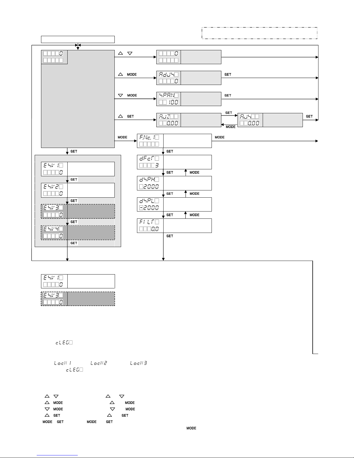
6. Key Operation Flowchart
POWER ON
ORP Display M
ode
+(3 sec)(*2) Manual (*2)
or Cleansing Cleansing mode
Output Mode (*1)
+(3sec)(*3) Adjustment
mode
+(3 sec) Span sensitivity
correction mode
+(3 sec) Trans. output Trans. output
Zero adjust. mode Span adjust. mode
ORP Input Group
Simple Setting Mode Moving average
EVT1 value data amount
Input high limit
EVT2 value
Input low limit
EVT3 value
ORP input filter time
EVT4 value constant
[About Setting Items]
EVT1 value
•
Upper left
:
ORP Display:
Indicates
the
setting item characters.
• Lower left: Setting Display: Indicates the factory default.
•
Right side: Indicates the
s
etting
item.
EVT3 value
Setting item in shaded section will be indicated only when
the corresponding option is ordered.
[Each Mode and Setting Items]
(*1) In ORP Display mode or Cleansing Output mode, measurement starts, indicating the item selected in [Backlight selection (p.49), ORP
color (p.49), Bar graph indication (p.50) and Setting Display indication (p.50)] in Special Function group. If power is turned ON again, the
last mode (ORP Display mode or Cleansing Output mode) from when power was turned OFF will resume.
(*2) If (Cleansing output) is selected in [EVT1 type to EVT4 type] in the EVT1 to EVT4 Action Groups, the unit will enter Manual
cleansing mode. After cleansing action is complete, the unit automatically reverts to Cleansing Output mode.
(*3) The unit cannot enter Adjustment mode or Span sensitivity correction mode in the following cases:
• (Lock 1), (Lock 2) or (Lock 3) is selected in [Set value lock (p.47)] in the Special Function group.
• When (Cleansing output) is selected in any of [EVT1 type to EVT4 type (pp. 23, 29, 35, 41)], and cleansing action is
performing using the ‘Cleansing time’ and ‘Restore time after cleansing’ settings.
[About Key Operation]
・
•+ (3 sec): Press and hold the and keys (in that order) together for 3 sec. The unit will enter Manual Cleansing mode.
・
•+ (3 sec): Press and hold the and keys (in that order) together for 3 sec.The unit will enter Adjustment mode.
・
•+ (3 sec): Press and hold the and keys (in that order) together for 3 sec. The unit will enter Span sensitivity correction mode.
・
•+ (3 sec): Press and hold the and keys (in that order) together for 3 sec. The unit will enter Transmission output Zero adjustment mode.
・
, : Press the or key. The unit will proceed to the next setting item, illustrated by an arrow.
・
To revert to ORP Display mode or Cleansing Output mode, press and hold the key for 3 sec. while in any mode.
①
②
Abbreviations: Sens.: Sensitivity, Correct.: Correction
Trans: Transmission Adjust: Adjustment

19
EVT1 Action EVT2 Action EVT3 Action
Group Group Group
EVT1 type Setting items: Same as item Setting items: Same as item
settings for EVT1 Action Group. settings for EVT1 Action Group.
For EVT2, read EVT1 column For EVT3, read EVT1 column
EVT1 value and substitute EVT1 with EVT2. and substitute EVT1 with EVT3.
(e.g.) (e.g.)
EVT1 proportional
band
EVT1 reset
EVT1 hysteresis
type
Output OFF time when
EVT1 ON side EVT1 output ON
EVT1 ORP input error
EVT1 OFF side alarm EVT type
EVT1 ORP input error
EVT1 ON delay alarm span when
time EVT output ON
EVT1 OFF delay EVT1 ORP input error
time alarm time when
EVT output ON
EVT1 proportional
cycle EVT1 ORP input error
alarm span when
EVT1 output high EVT output OFF
limit
EVT1 ORP input error
EVT1 output low alarm time when
limit EVT output OFF
Output ON time when EVT1 cycle variable
EVT1 output ON range
EVT1 cycle extended
time
①
③
②④

20
EVT4 Action Special Function
Group Group
Setting items: Same as item Set value lock
settings for EVT1 Action Group.
For EVT4, read EVT1 column
and substitute EVT1 with EVT4. Communication
(e.g.) protocol
Instrument
number
Communication ORP color
speed reference value
Data bit/Parity ORP color range
Stop bit Backlight time
Transmmision Bar graph indication
output type
Transmmision EVT output when
output high limit input errors occur
Transmmision Setting Display
output low limit indication
Trans. output status Number of cleansing
in Adjust. mode, Span cycles
sensitivity correct.mode
Cleansing interval
Set value HOLD
Cleansing time
Backlight selection
Restore time after
ORP color cleansing
ORP input error
alarm time unit
③
④
Abbreviations: Trans.: Transmission Adjust: Adjustment
Correct: Correction
Other manuals for AER-101-ORP
1
Table of contents
Other Shinko Measuring Instrument manuals


Popular Measuring Instrument manuals by other brands


PASCO
PASCO PS-2600 reference guide

PCB Piezotronics
PCB Piezotronics IMI SENSORS M625B00 Installation and operating manual

Ludlum Measurements
Ludlum Measurements 177 manual

Johnson Controls
Johnson Controls FMS-1655M installation instructions

Sylvac
Sylvac Hi Cal instructions

Micromeritics
Micromeritics GEMINI VII KEYPAD Operator's manual


