Shinko WIL-101-ORP User manual
Plug-in Type
Digital Indicating ORP Meter
WIL-101-ORP
Instruction Manual

2
Preface
Thank you for purchasing our WIL-101-ORP, Plug-in Type Digital Indicating ORP Meter.
This manual contains instructions for the mounting, functions, operations and notes when operating the
WIL-101-ORP. To ensure safe and correct use, thoroughly read and understand this manual before using
this instrument.
To prevent accidents arising from the misuse of this instrument, please ensure the operator receives this
manual.
Characters Used in This Manual
Indication
Number, / -1 0 1 2 3 4 5 6 7 8 9
Indication
Alphabet A B C D E F G H I J K L M
Indication
Alphabet N O P Q R S T U V W X Y Z
Caution
• This instrument should be used in accordance with the specifications described in the manual.
If it is not used according to the specifications, it may malfunction or cause a fire.
• Be sure to follow all of the warnings, cautions and notices. If they are not observed, serious injury or
malfunction may occur.
• The contents of this instruction manual are subject to change without notice.
• Care has been taken to assure that the contents of this instruction manual are correct, but if there are any
doubts, mistakes or questions, please inform our sales department.
• This instrument is designed to be installed on a DIN rail within a control panel. If it is not, measures must be
taken to ensure that the operator cannot touch power terminals or other high voltage sections.
• Any unauthorized transfer or copying of this document, in part or in whole, is prohibited.
• Shinko Technos Co., Ltd. is not liable for any damage or secondary damage(s) incurred as a result of
using this product, including any indirect damage.
Safety Precautions (Be sure to read these precautions before using our products.)
The safety precautions are classified into 2 categories: “Warning” and “Caution”.
Depending on the circumstances, procedures indicated by Caution may result in serious
consequences, so be sure to follow the directions for usage.
Warning
Caution
Procedures which may lead to dangerous conditions and cause death or
serious injury, if not carried out properly.
Procedures which may lead to dangerous conditions and cause superficial to
medium injury or physical damage or may degrade or damage the product, if
not carried out properly.

3
Warning
• To prevent an electrical shock or fire, only Shinko or other qualified service personnel may handle the
inner assembly.
• To prevent an electrical shock, fire or damage to the instrument, parts replacement may only be
undertaken by Shinko or other qualified service personnel.
SAFETY PRECAUTIONS
• To ensure safe and correct use, thoroughly read and understand this manual before using this
instrument.
• This instrument is intended to be used for industrial machinery, machine tools and measuring
equipment. Verify correct usage after purpose-of-use consultation with our agency or main office.
(Never use this instrument for medical purposes with which human lives are involved.)
• External protection devices such as protective equipment against excessive temperature rise, etc.
must be installed, as malfunction of this product could result in serious damage to the system or
injury to personnel. Also proper periodic maintenance is required.
•
This instrument must be used under the conditions and environment described in this manual.
Shinko Technos Co., Ltd. does not accept liability for any injury, loss of life or damage occurring due
to the instrument being used under conditions not otherwise stated in this manual.
Caution with respect to Export Trade Control Ordinance
To avoid this instrument from being used as a component in, or as being utilized in the manufacture of
weapons of mass destruction (i.e. military applications, military equipment, etc.), please investigate
the end users and the final use of this instrument. In the case of resale, ensure that this instrument is
not illegally exported.
PRECAUTIONS
1. Installation Precautions
Caution
This instrument is intended to be used under the following environmental conditions (IEC61010-1):
• Overvoltage category , Pollution degree 2
Ensure the mounting location corresponds to the following conditions:
• A minimum of dust, and an absence of corrosive gases
• No flammable, explosive gases
• No mechanical vibrations or shocks
• No exposure to direct sunlight, an ambient temperature of 0 to 50 (32 to 122 ) that does not
change rapidly, and no icing
• An ambient non-condensing humidity of 35 to 85 %RH
• No large capacity electromagnetic switches or cables through which large current is flowing.
• No water, oil or chemicals or where the vapors of these substances can come into direct contact
with the unit
• If the WIL-101-ORP is installed within a control panel, the ambient temperature of the unit – not the
ambient temperature of the control panel – must be kept to under 50 . Otherwise the life of
electronic parts (especially electrolytic capacitors) of the unit will be shortened.
Note: Do not install this instrument on or near flammable material even though the case of this
instrument is made of flame-resistant resin.
4
2. Wiring Precautions
Caution
• Do not leave wire remnants in the instrument, as they could cause a fire or a malfunction.
• Use a solderless terminal with an insulation sleeve in which the M3 screw fits when wiring the
WIL-101-ORP.
• Tighten the terminal screw using the specified torque. If excessive force is applied to the screw
when tightening, the terminal screw may be damaged.
• This instrument does not have a built-in power switch, circuit breaker and fuse.
It is necessary to install a power switch, circuit breaker and fuse near the instrument.
(Recommended fuse: Time-lag fuse, rated voltage 250 V AC, rated current 2 A)
• For a 24 V AC/DC power source, do not confuse polarity when using direct current (DC).
• Do not apply a commercial power source to the sensor which is connected to the input terminal nor
allow the power source to come into contact with the sensor.
• Use the ORP Combined Electrode Sensor in accordance with the sensor input specifications of the
WIL-101-ORP.
• Keep the input wires and power line separate.
Note about the ORP Combined Electrode Sensor Cable
The ORP Combined Electrode Sensor cable is a highly-insulated (electrical) cable. Please handle it
with utmost care as follows.
• Do not allow terminals and socket of the ORP Combined Electrode Sensor cable to come in contact
with moisture or oil of any kind. Likewise, ensure fingers are clean, otherwise the insulation will
deteriorate, resulting in unstable indication.
Be sure to keep the cable dry and clean at all times.
If the cable is stained, clean it with alcohol, and dry it completely.
• For calibration or electrode checking/replacement, the ORP Combined Electrode Sensor cable
should be wired with sufficient length.
• Keep the ORP Combined Electrode Sensor cable and junction cable away from electrical devices,
such as motors or their power lines from which inductive interference emanates.
Connection
The ORP Combined Electrode Sensor cable has the following terminals.
Symbol Terminal
M Metal electrode terminal
R Reference electrode terminal
3. Operation and Maintenance Precautions
Caution
• Do not touch live terminals. This may cause an electrical shock or problems in operation.
• Turn the power supply to the instrument OFF when retightening the terminal or cleaning.
Working on or touching the terminal with the power switched ON may result in severe injury or death
due to electrical shock.
• Use a soft, dry cloth when cleaning the instrument.
(Alcohol based substances may tarnish or deface the unit.)
• As the display section is vulnerable, do not strike or scratch it with a hard object or put pressure on it.

5
Contents
1. Model Page
1.1 Model ---------------------------------------------------------------------------------- 7
1.2 How to Read the Model Label --------------------------------------------------- 7
2. Names and Functions of Sections ---------------------------------------------- 8
3. Mounting to the Control Panel
3.1 Site Selection ---------------------------------------------------------------------- 9
3.2 External Dimensions (Scale: mm) --------------------------------------------- 9
3.3 Mounting ---------------------------------------------------------------------------- 9
4. Removal -------------------------------------------------------------------------------- 11
5. Wiring ----------------------------------------------------------------------------------- 12
5.1 Lead Wire Solderless Terminal ------------------------------------------------ 13
5.2 Terminal Arrangement ------------------------------------------------------------ 13
5.3 Wire the Communication Line -------------------------------------------------- 14
6. Outline of Key Operation and Setting Groups
6.1 Outline of Key Operation -------------------------------------------------------- 16
6.2 Setting Groups --------------------------------------------------------------------- 16
7. Key Operation Flowchart --------------------------------------------------------- 18
8. Setup
8.1 Turn the Power Supply to the WIL-101-ORP ON ------------------------- 20
8.2 ORP Input Function Group ----------------------------------------------------- 20
8.3 Output Function Group ---------------------------------------------------------- 21
8.4 Special Function Group --------------------------------------------------------- 26
9. Calibration
9.1 Adjustment Mode ----------------------------------------------------------------- 33
9.2 Span Sensitivity Correction Mode -------------------------------------------- 34
9.3 Transmission Output Adjustment Mode ------------------------------------- 35
10. Measurement
10.1 Starting Measurement --------------------------------------------------------- 36
10.2 A Output --------------------------------------------------------------------- 36
10.3 ORP Input Error Alarm -------------------------------------------------------- 36
10.4 Cleansing Output --------------------------------------------------------------- 37
10.5 Manual Cleansing Mode ------------------------------------------------------ 38
10.6 Transmission Output ----------------------------------------------------------- 38
11. Communication
11.1 System Configuration Example ---------------------------------------------- 39
11.2 Setting Method of the ORP Meter ------------------------------------------- 39
11.3 Communication Procedure --------------------------------------------------- 40
11.4 Shinko Protocol
11.4.1 Transmission Mode ------------------------------------------------------ 41
11.4.2 Command Configuration ------------------------------------------------ 41
11.4.3 Checksum Calculation -------------------------------------------------- 42
11.5 Modbus Protocol
11.5.1 Transmission Mode ------------------------------------------------------ 43
11.5.2 Data Communication Interval ----------------------------------------- 43
11.5.3 Message Configuration ------------------------------------------------- 43
11.5.4 Message Example ------------------------------------------------------- 45

6
11.6 Communication Command Table
11.6.1 Notes about Setting/Reading Command --------------------------- 47
11.6.2 Setting/Reading Command -------------------------------------------- 47
11.6.3 Read Only Command --------------------------------------------------- 51
11.7 ORP Calibration and Transmission Output Adjustment
via Communication Command --------------------------------------------- 52
11.7.1 Adjustment Mode --------------------------------------------------------- 52
11.7.2 Span Sensitivity Correction Mode ----------------------------------- 52
11.7.3 Transmission Output Adjustment ------------------------------------ 53
11.8 Notes on Programming Monitoring Software
11.8.1 How to Speed up the Scan Time ------------------------------------- 54
11.8.2 How to Read the Set Value Changes
Made by Front Keypad Operation ------------------------------------ 54
11.8.3 Note when Sending All Set Values Simultaneously ------------- 54
12. Specifications
12.1 Standard Specifications ------------------------------------------------------- 55
12.2 Optional Specifications -------------------------------------------------------- 58
13. Troubleshooting
13.1 Indication -------------------------------------------------------------------------- 60
13.2 Key Operation -------------------------------------------------------------------- 60
13.3 Communication ------------------------------------------------------------------ 61
14 Character Tables ------------------------------------------------------------------- 62

7
1. Model
1.1 Model
W I L - 1 0 1 -ORP ,
Input Points 1 1 point
Input ORP ORP Combined Electrode Sensor
100 to 240 V AC (standard)
Supply Voltage 1 24 V AC/DC (*1)
EVT A output (A11, A12, A21, A22)
Option TA Transmission output (*2)
(*1) Supply voltage 100 to 240 V AC is standard.
When ordering 24 V AC/DC, enter “1” after the input code.
(*2) If the TA option is ordered, the EVT option (A1 output only) will be automatically added.
1.2 How to Read the Model Label
The model label is attached to the left side of the case.
(Fig. 1.2-1)
Model, Option
Input
Supply voltage, Power consumption
Serial number
Manufacturer
Factory ID
RoHS directive compliant

8
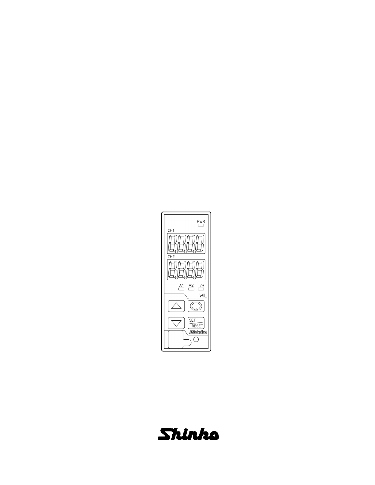
2. Names and Functions of Sections
(Fig. 2-1)
Displays
ORP Display: ORP value or characters in setting mode are indicated in red.
Setting Display: Values in setting mode are indicated in red.
Indications differ depending on the selections in [Setting Display indication (p.27)].
Unit labels
Unit label: Attach the user’s unit of ORP Display and Setting Display from the included unit
labels if necessary.
Action Indicators
Power Indicator: When power supply to the instrument is turned ON, the yellow LED is lit.
A1 Indicator: When A1 output (Contact output 1) is ON, the red LED is lit.
A2 Indicator: When A2 output (Contact output 2) is ON, the yellow LED is lit.
T/R Indicator: The yellow LED is lit during Serial communication TX output (transmitting).
Keys
UP key: Increases the numeric value.
DOWN key: Decreases the numeric value.
MODE key: Selects a setting group.
SET/RESET key: Switches the setting modes, and registers the set value.
Light Sensor: Automatically measures and controls brightness of the ORP Display,
Setting Display and Action indicators.
Notice
When setting the specifications and functions of this instrument, connect mains power cable to terminals
13 and 14 first, then set them referring from “6. Outline of Key Operation and Setting Groups” to “8.
Setup (pages 17 to 32)” before performing “3. Mounting to the Control Panel (p.9)” and “5. Wiring (p.12)”.
A2 Indicator
ORP Display
Setting Display
A1 Indicator
UP key
DOWN key
Power Indicator
T/R Indicator
MODE key
SET/RESET key
Light Sensor
Unit label
Unit label

9
3. Mounting to the Control Panel
3.1 Site Selection
Caution
Use within the following temperature and humidity ranges.
Temperature: 0 to 50 (32 to 122 ) (No icing), Humidity: 35 to 85 %RH (Non-condensing)
If the WIL-101-ORP is installed within a control panel, the ambient temperature of the unit – not the
ambient temperature of the control panel – must be kept to under 50 . Otherwise the life of
electronic parts (especially electrolytic capacitors) of the unit will be shortened.
This instrument is intended to be used under the following environmental conditions (IEC61010-1):
Overvoltage category , Pollution degree 2
Ensure the mounting location corresponds to the following conditions:
• A minimum of dust, and an absence of corrosive gases
• No flammable, explosive gases
• No mechanical vibrations or shocks
• No exposure to direct sunlight, an ambient temperature of 0 to 50 (32 to 122 ) that does not
change rapidly
• An ambient non-condensing humidity of 35 to 85 %RH
• No large capacity electromagnetic switches or cables through which large current is flowing
• No water, oil or chemicals or where the vapors of these substances can come into direct contact
with the unit
3.2 External Dimensions (Scale: mm)
(Fig. 3.2-1)
3.3 Mounting
(1) Hook the upper part of the socket on the DIN rail, and mount it (A clicking sound is heard).
(Fig. 3.3-1)
Hook the upper part of the
socket on the DIN rail.
Socket (sold separately)
DIN rail
85
3
30 108
79 (29)
3.3

10
Caution
Before inserting the WIL-101-ORP into the socket, wire the unit while referring to Section “5. Wiring”
(p.12).
(2) Check that the Lock Release has been lowered.
(Fig. 3.3-2)
(3) Insert the WIL-101-ORP into the socket.
(Fig. 3.3-3)
(4) Fix the WIL-101-ORP and the socket by pushing the Lock Release up.
(Fig. 3.3-4)
When inserting, be careful about
the position of pins and slots.
Lock Release
Lock Release
Check that the WIL-101-ORP and the socket
are locked by pushing the Lock Release up.

11
4. Removal
(1) Turn the power supply to the unit OFF.
(2) Pull the Lock Release down, and release the WIL-101-ORP from the socket.
(Fig. 4-1)
(3) Separate the WIL-101-ORP from the socket.
(Fig. 4-2)
(4) Remove the socket from the DIN rail by pulling the socket Lock Release
(at the bottom of the socket) down.
(Fig. 4-3)
Lock Release
Check that the WIL-101-ORP and
the socket are unlocked by pulling
the Lock Release down.
Lock Release
12
5. Wiring
Warning
Turn the power supply to the instrument off before wiring or checking.
Working on or touching the terminal with the power switched on may result in severe injury
or death due to electrical shock.
Caution
• Do not leave wire remnants in the instrument, as they could cause a fire or a malfunction.
• Use a solderless terminal with an insulation sleeve in which the M3 screw fits when wiring the unit.
• Tighten the terminal screw using the specified torque. If excessive force is applied to the screw
when tightening, the terminal screw may be damaged.
• This instrument does not have a built-in power switch, circuit breaker or fuse.
It is necessary to install a power switch, circuit breaker or fuse near the instrument.
(Recommended fuse: Time-lag fuse, rated voltage 250 V AC, rated current 2 A)
• For a 24 V AC/DC power source, do not confuse polarity when using direct current (DC).
• Do not apply a commercial power source to the sensor which is connected to the input terminal
nor allow the power source to come into contact with the sensor.
• Use the ORP Combined Electrode Sensor in accordance with the sensor input specifications of this unit.
• Keep the input wires and power line separate.
Note about the ORP Combined Electrode Sensor Cable
The ORP Combined Electrode Sensor cable is a highly-insulated (electrical) cable. Please handle it
with utmost care as follows.
• Do not allow terminals and socket of the ORP Combined Electrode Sensor cable to come in contact
with moisture or oil of any kind. Likewise, ensure fingers are clean, otherwise the insulation will
deteriorate, resulting in unstable indication. Be sure to keep the cable dry and clean at all times.
If the cable is stained, clean it with alcohol, and dry it completely.
• For calibration or electrode checking/replacement, the ORP Combined Electrode Sensor cable should
be wired with sufficient length.
• Keep the ORP Combined Electrode Sensor cable and junction cable away from electrical devices,
such as motors or their power lines from which inductive interference emanates.
Connection
The ORP Combined Electrode Sensor cable has the following terminals.
Symbol Terminal
M Metal electrode terminal
R Reference electrode terminal

13
5.1 Lead Wire Solderless Terminal
Use a solderless terminal with an insulation sleeve in which an M3 screw fits as follows.
The tightening torque should be 0.63 N•m.
Solderless
Terminal Manufacturer Model
Y-type Nichifu Terminal Industries CO.,LTD. TMEV1.25Y-3S
(Fig. 5.1-1)
5.2 Terminal Arrangement
M, R: Electrode sensor terminals ( 1-2)
ORP Combined Electrode Sensor
A1: A1 output (Contact output 1) terminals
(9-10 )
(When the EVT option or TA option is
ordered)
A2: A2 output (Contact output 2) terminals
(11 -12 )
(When the EVT option is ordered)
TRANSMIT OUTPUT:
Transmission output terminals (
11
-12 )
(When the TA option is ordered)
POWER SUPPLY: Power terminals ( 13 -
14
)
24 V AC/DC (Enter 1 after the input
code.)
RS-485: Serial Communication modular jack
Modular Jack Pin (WIL-101-ORP side arrangement)
(Fig. 5.2-1)
3
.2
mm
or more
5.
9
mm
or less
4 mm or less
4
.8
mm
or more

14
WIL-101-ORP (Max 31 units)
CDD or CPP (sold-separately)
CMC-001-3 (sold-separately)
Bottom of WIL-101-ORP
Host computer
USB port
5.3 Wire the Communication Line
Connect to the modular jack at the bottom of the instrument, using CDD or CPP (sold separately).
•Wiring Example Using a USB Communication cable CMC-001-3 (sold-separately)
(Fig. 5.3-1)
•Wiring Example Using a Communication Converter IF-400 (sold-separately)
(Fig. 5.3-2)
Bottom of IF-400, WIL-101-ORP
Host Computer
D-sub 9-pin Connector
Shield
Wire FG
WIL-101-ORP (Max 31 units)
IF-400 (Sold Separately)
CDD or CPP (sold separately)

15
Shield Wire
Be sure to ground only one end of the shield wire so that current cannot flow to the shield wire.
If both ends of the shield wire are grounded, the circuit will be closed, resulting in a ground loop.
This may cause noise. Be sure to ground the FG terminal.
Recommended cable: OTSC-VB 2PX0.5SQ (made by Onamba Co., Ltd.) or equivalent
(Use a twisted pair cable.)
Terminator (Terminal Resistor)
The terminator is mounted at the end of the wire when connecting a personal computer with
multiple peripheral devices. The terminator prevents signal reflection and disturbance.
Do not connect a terminator with the communication line because each WIL-101-ORP has
built-in pull-up and pull-down resistors instead of a terminator.
Communication converter IF-400 (sold separately) has a built-in terminal resistor.

16
6. Outline of Key Operation and Setting Groups
6.1 Outline of Key Operation
Setting items are divided into groups, and group selection has to be made with keypads.
Press the key in ORP Display Mode or Cleansing Output Mode. The unit enters Group Selection
Mode.
Select a group with the key, and press the key. The unit enters each setting item.
To set each setting item, use the or key, and register the set value with the key.
6.2 Setting Groups
Power ON
+ (3 sec) (*2) (*2)
ORP Display Mode or Manual Cleansing Mode
Cleansing Output Mode
(*1) + (3 sec) (*3)
Adjustment Mode
+ (3 sec) (*3)
Span Sens.Correc. Mode
+ (3 sec)
Transmission Output Transmission Output
Zero Adjust. Mode Span Adjust. Mode
Group Selection Mode See pages 20-32 for details of each setting item.
ORP Input Function Moving average A output when
Group data amount input errors occur
Output Function A11 type A22 OFF delay time
Group
Special Function Set value lock Restore time after
Group cleansing
(*1) Measurement starts, indicating ORP in the ORP Display, and the item selected in [Setting Display indication (p.27)]
of Special function group in the Setting Display. If power is turned ON again, the last mode (ORP Display Mode or
Cleansing Output Mode) from when power was turned OFF will resume.
(*2) If (Cleansing output) is selected in any of [A11, A12, A21, A22 type (pp.21, 22)] in the Output Function
Group, the unit will enter Manual Cleansing Mode.
After cleansing action is complete, the unit automatically reverts to Cleansing Output Mode.
Abbreviation
s
:
Sens.: Sensitivity
Correc.: Correction
Adjust.: Adjustment

17
(*3) The unit cannot enter Adjustment Mode or Span Sensitivity Correction Mode in the following cases:
• When (Lock 1),( Lock 2) or (Lock 3) is selected in [Set value lock (p.26)] in the Special
Function Group
• When (Cleansing output) is selected in any of [A11, A12, A21, A22 type (pp.21, 22)] in the Output Function
Group, and cleansing action is performing using the ‘Cleansing time’ and ‘Restore time after cleansing’ settings.
: Available only when the TA option is ordered.
About Key Operation
• + (3 sec): Press and hold the key and key (in that order) together for 3 seconds.
The unit will proceed to Manual Cleansing Mode.
• + (3 sec): Press and hold the key and key (in that order) together for 3 seconds.
The unit will proceed to Adjustment Mode.
• + (3 sec): Press and hold the key and key (in that order) together for 3 seconds.
The unit will proceed to Span Sensitivity Correction Mode.
• + (3 sec): Press and hold the key and key (in that order) together for 3 seconds.
The unit will proceed to Transmission Output Zero Adjustment Mode.
• or : Press the or key. The unit will proceed to the next setting item,
illustrated by an arrow.
• or : Press the or key until the desired setting mode appears.
• To revert to ORP Display Mode or Cleansing Output Mode, press and hold the key for 3
seconds while in any mode.
18
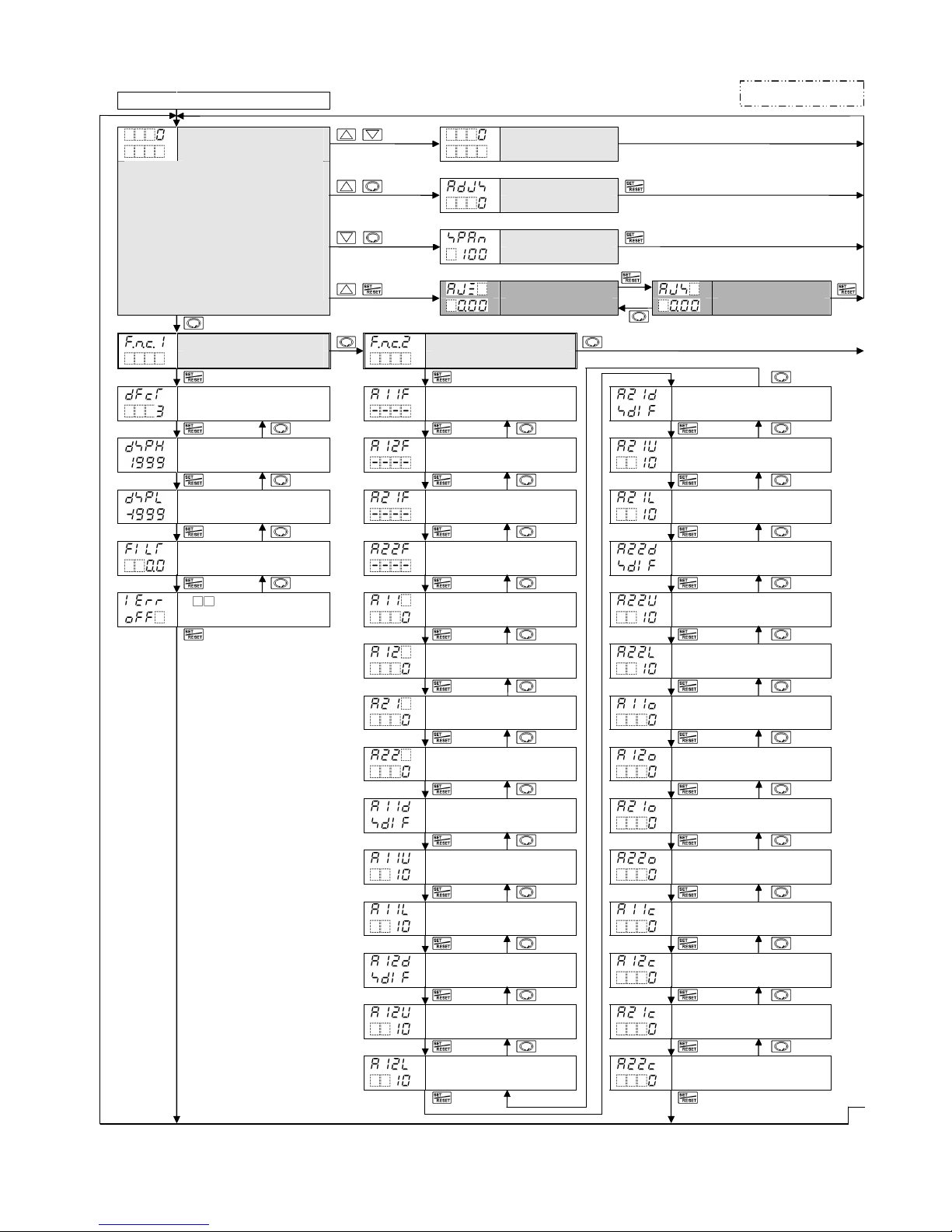
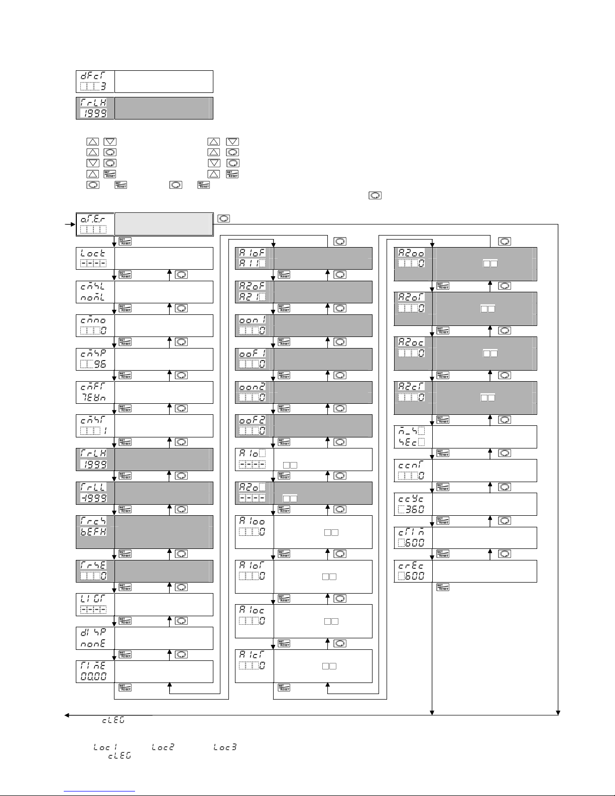
7. Key Operation Flowchart
Power ON
ORP Display Mode or + (3sec) (*1) Manual Cleansing (*1)
Cleansing Output Mode mode
+ (3sec) (*2) Adjustment
mode
+ (3sec) (*2) Span Sensitivity
Correction mode
+ (3 sec) Transmission output Transmission output
In ORP Display Mode or Cleansing Output
Mode, measurement starts, indicating ORP
in the ORP Display and an item selected
in [Setting Display indication (p.27)] of Special
function group in the Setting Display.
If power is turned ON again, the last mode
(ORP Display Mode or Cleansing Output
Mode) from when power was turned OFF
will resume.
Zero adjust. mode Span adjust. mode
ORP Input Function Output Function
Group Group
Moving average A11 type A21 hysteresis type
data amount
Input high limit A12 type A21 ON side
Input low limit A21 type A21 OFF side
ORP input A22 type A22 hysteresis type
filter time constant
A output when input A11 value A22 ON side
errors occur
A12 value A22 OFF side
A21 value A11 ON delay time
A22 value A12 ON delay time
A11 hysteresis type A21 ON delay time
A11 ON side A22 ON delay time
A11 OFF side A11 OFF delay time
A12 hysteresis type A12 OFF delay time
A12 ON side A21 OFF delay time
A12 OFF side A22 OFF delay time
①
②
Abbreviation:
Adjust.: Adjustment
19
●About Setting Items
Moving average • Upper left: ORP Display: Indicates the setting item characters.
data amount • Lower left: Setting Display: Indicates the factory default. • Right side: Indicates the setting item.
Transmission output Setting item in shaded section will be indicated only when the corresponding option is ordered.
high limit A2 related items cannot be used if TA option is ordered.
●About Key Operation
• + (3 sec): Press and hold , keys (in that order) for 3 sec. The unit enters Manual Cleansing Mode.
• + (3 sec): Press and hold , keys (in that order) for 3 sec. The unit enters Adjustment Mode.
• + (3 sec): Press and hold , keys (in that order) for 3 sec. The unit enters Span Sensitivity Correction Mode
• + (3 sec): Press and hold , keys (in that order) for 3 sec. The unit enters Transmission Output Zero Adjustment Mode.
• or : Press the or key. The unit enters the next setting item, illustrated by an arrow.
• To revert to ORP Display Mode or Cleansing Output Mode, press and hold the key for 3 sec while in any mode.
Special Function
Group
Set value lock A1 output allocation A2 ORP input error alarm
span when A output
ON
Communication A2 output allocation
protocol A2 ORP input error alarm
time when A output
Instrument number Output ON time ON
when A1 output ON
A2 ORP input error alarm
Communication Output OFF time span when A output
speed when A1 output ON OFF
Data bit/Parity Output ON time A2 ORP input error alarm
when A2 output ON time when A output
OFF
Stop bit Output OFF time
when A2 output ON ORP input error alarm
time unit
Transmission output A1 ORP input error alarm
high limit A type Number of cleansing
cycles
Transmission output A2 ORP input error alarm
low limit A type Cleansing interval
Transmission output status A1 ORP input error alarm
in Adjustment Mode, Span span when A output Cleansing time
Sensitivity Correction Mode ON
Set value HOLD A1 ORP input error alarm Restore time after
time when A output cleansing
ON
Auto-light function
A1 ORP input error alarm
span when A output
Setting Display OFF
indication
A1 ORP input error alarm
Indication time time when A output
OFF
(*1) When (Cleansing Output) is selected in any of [A11, A12, A21, A22 type (pp.21, 22)] in the Output Function Group, the unit will enter Manual
Cleansing Mode. After cleansing is complete, the unit automatically reverts to Cleansing Output Mode.
(*2) The unit cannot enter Adjustment Mode or Span Sensitivity Correction Mode in the following cases.
•If (Lock 1),(Lock 2) or (Lock 3) is selected in [Set value lock (p.26)] in the Special Setting Group
•When (Cleansing output) is selected in any of [A11, A12, A21, A22 type (pp.21, 22)] in the Output Function Group, and cleansing action
is performing using the ‘Cleansing time’ and ‘Restore time after cleansing’ settings.
①
②

20
8. Setup
Setup should be done before using this instrument, according to the user’s conditions:
Setting the ORP input function (input high limit, input low limit), Output function (A11, A12, A21, A22
types), Special function (Communication, Cleansing action, etc.).
Setup can be conducted in the ORP Input Function Group, Output Function Group and Special Function
Group.
If the user’s specification is the same as the factory default of the WIL-101-ORP, or if setup has already
been completed, it is not necessary to set up the instrument. Proceed to Section “9. Calibration (p.33)”.
8.1 Turn the Power Supply to the WIL-101-ORP ON.
For approx. 4 seconds after the power is switched ON, is indicated in the ORP Display.
During this time, all outputs are in OFF status, and LED indicators except the Power Indicator go off.
After that, measurement starts, indicating ORP in the ORP Display and an item selected in [Setting
Display indication (p.27)] in the Setting Display.
This status is called ORP Display Mode or Cleansing Output Mode.
8.2 ORP Input Function Group
To enter the ORP Input Function Group, follow the procedure below.
1Press the Key once in ORP Display Mode or Cleansing Output Mode.
2Press the Key once.
The unit proceeds to the ORP Input Function Group, and ’Moving average data amount’ appears.
Character Setting Item, Function, Setting Range Factory Default
Moving average data amount 3
• Sets the number of ORP inputs for calculating the moving average.
• Setting range: 1 to 20
Input high limit 1999 mV
• Sets the high limit value for ORP input indication.
• Setting range: Input low limit value to 1999 mV
Input low limit -1999 mV
• Sets the low limit value for ORP input indication.
• Setting range: -1999 mV to Input high limit value
ORP input filter time constant 0.0 sec.
• Sets ORP input filter time constant.
If the value is set too large, it affects A output due to the delay of response.
• Setting range: 0.0 to 60.0 seconds
A output when input errors occur Disabled
• If input errors, such as ORP Combined Electrode Sensor burnout or short-circuited
occur, A output Enabled/Disabled can be selected.
If “Enabled” is selected, A output and A output status will be maintained
when input errors occur.
If “Disabled” is selected, A output and A output status will be turned OFF
when input errors occur.
• If (Cleansing output) is selected in [A type], cleansing action takes
priority regardless of this selection.
• : Enabled
: Disabled
Table of contents
Other Shinko Measuring Instrument manuals


Popular Measuring Instrument manuals by other brands

Bender
Bender Isometer IR420-D4 manual

Renkforce
Renkforce A460 operating instructions

Agilent Technologies
Agilent Technologies 2100 Bioanalyzer System Installation and safety guide

Burster
Burster TRANS CAL 7270 user manual

Electrex
Electrex KILO F RJ45 installation instructions

Elvaco
Elvaco CMi6140 quick start guide


SIMARINE
SIMARINE SDI01 user manual

Mark-10
Mark-10 2 Series quick start guide

AR
AR DC7490 Operating and service manual

TSI Incorporated
TSI Incorporated IAQ-CALC 7515 Operation and service manual

Tektronix
Tektronix TLA7S08 instruction manual

Endress+Hauser
Endress+Hauser Analytikjena SELECT Head 8/250 ml operating manual