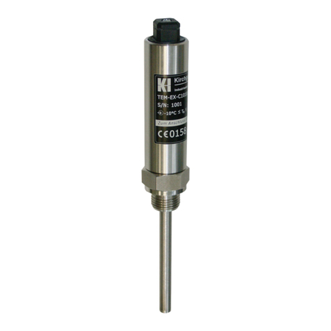
kirchgaesser MIDEX-H Series User manual

ba023000en; Rev. 2.6
Operating
instructions
Flow meter
MIDEX
D
I
N
o
t
E
g
N
n
i
d
I
S
r
o
O
c
c
9
a
0
0
d
1
e
i
:
f
2
i
t
0
r
1
e
5
C
Q
M
m
e
t
s
s
y
*
*
QM

II
MIDEX
Kirchgaesser Industrieelektronik GmbH
Am Rosenbaum 6
D-40882 Ratingen (Homberg)
Tel.: +49 (0)2102 / 955 - 6
Fax: +49 (0)2102 / 955 - 720
www.kirchgaesser.com
info@kirchgaesser.com

MIDEX
Kirchgaesser Industrieelektronik GmbH III
Table of contents
1. Introduction .........................................................................................................................4
1.1 Safety conventions............................................................................................................................................ 4
1.2 Using the instrument correctly........................................................................................................................... 4
1.3 Table of versions ............................................................................................................................................... 5
1.4 Certication ....................................................................................................................................................... 6
1.5 Measuring principle ........................................................................................................................................... 6
1.6 Measuring ranges.............................................................................................................................................. 7
1.7 Volume-nominalwidths-velocityofow......................................................................................................... 8
2. Installation ...........................................................................................................................9
3. Electrical connection........................................................................................................11
3.1 Terminal and pin assignment........................................................................................................................... 12
3.2 Terminals of temperature sensor MTF ............................................................................................................ 15
4. Controls .............................................................................................................................16
4.1 Controls of MIDEX........................................................................................................................................... 16
4.2 Function selection ........................................................................................................................................... 17
4.3 Menu 1: Display............................................................................................................................................... 19
4.4 Menu 2: Parameter.......................................................................................................................................... 21
4.5 Menu 3: In-/Outputs......................................................................................................................................... 25
4.6 Menu 4: Diagnosis........................................................................................................................................... 29
4.7 Menu 5: Hardware........................................................................................................................................... 32
4.8 Menu 6: Calibration ......................................................................................................................................... 35
4.9 Overview of default values .............................................................................................................................. 37
5. Display and output of measuring data............................................................................39
5.1 Normal operation............................................................................................................................................. 39
5.2 Overrange ....................................................................................................................................................... 39
5.3 Medium missing .............................................................................................................................................. 40
5.4 Error ................................................................................................................................................................ 40
5.5 EEPROM error ................................................................................................................................................ 41
5.6 Pulse output .................................................................................................................................................... 41
6. Dimension sheets .............................................................................................................42
7. Technical data ...................................................................................................................45

4
MIDEX
Kirchgaesser Industrieelektronik GmbH
Introduction
1. Introduction
1.1 Safety conventions
In order to highlight safety-relevant or alternate operation procedures in the manual
the following conventions have been used, each indicated by a corresponding icon in
the margin:
!A note highlights actions or procedures which, if not performed correctly,
mayindirectlyaectoperatingormayleadtoaninstrumentresponce
which is not planned.
"Caution indicates actions or procedures which, if not performed correctly,
may lead to personal injury or incorrect functioning of the instrument.
#A warning indicates actions or procedures which, if not performed cor-
rectly, will lead to personal injury, a safety hazard or destruction of the
instrument.
1.2 Using the instrument correctly
MIDEX-devices are manufactured according to the state of the art for operating
safety and comply with the relevant regulations. Improper use or use contrary to
specicationsmight,however,causedanger.
The manufacturer shall not be held liable for any damages arising from improper use
orfromusecontrarytospecication.
UnlessexpresslyprovidedforinthisOperatingManual,modicationsoralterationsof
the devices shall not be permitted.
Theowmeterisdesignedformeasuringtheowofelectricallyconductiveuidswith
a minimum conductivity of 5 µS / cm such as water, emulsions, sludges, slurries and
pastes. It operates without any wear and tear and dispenses without moving parts.
MIDEXisaowmeasuringdevicewhichallowsoptionalmeasuringoftwo
temperatures. Thus it can also be utilised for measuring refrigerating or heating
capacity.Anotheroptionisthetotalizingcountertodisplaythevolumewhichowed
through. This function is a special version.
TheMIDEXowmeterisaheavyduty,ameproofandcompactdeviceespecially
designed for mining applications, and complies with the harmonised European
standards EN 50014 (and EN 60079-0 resp.) and EN 50020 (and EN 60079-11 resp.)
as well as the European directive 2014/34/EU (ATEX).
It is available in the nominal widths from DN 50 to DN 300. The instruments are
available in the nominal pressure of PN 10 to PN 500. The enclosure is made of
stainless steel.
Thetransportofthisdeviceisallowedonlywiththerightxingat
theange(e.g.byliftingeyebolts).Impropertransportcanlead
to irreparable damaging of this measuring instrument.

MIDEX
Kirchgaesser Industrieelektronik GmbH 5
Introduction
1.3 Table of versions
MIDEX - /
nominal pressure / bar
nominal width / mm
H vulcanite lining
M internal lining for building material, right for scraper
P plastic lining
S special lining
Fangedversion
H high pressure coupling
S special coupling
S without totalizing counter
T with totalizing counter
S standard version with 4 potential-free outputs
E extended version with 8 potential-free outputs
T version with temperature sensors and 8 potential-free
outputs
H Hydrostar socket type SKK 24-M
K connection via terminals
M Machaczek socket type ME2A10, ME2A60 or ME2A80
P1 PROMOS socket type BN4160, power supply and out-
put on one socket
P2 PROMOS socket type BN4160, separate voltage
supply via terminals, inputs and outputs are potential-
seperated
The standard measuring range of the optional used temperature sensors is adjusted
to 0 - 50 °C. It is freely programmable between -20°C and +60°C.
The standard length of the sensor is 100 mm. Other lengths are available on request.
The maximum cable lenght of the MTF is 30 m.

6
MIDEX
Kirchgaesser Industrieelektronik GmbH
Introduction
1.4 Certication
TheowmeterMIDEXcorrespondstotheharmonizedEuropeanstandards
EN 50014 (and EN 60079-0 resp.) and EN 50020 (and EN 60079-11 resp.) as soon
as the European directive 2014/34/EU (ATEX).
TheMIDEXisapprovedinallvariantswiththeECType-Examinationcerticateno.
DMT 02 ATEX E 115. It is marked with I M2 EEx ia I.
1.5 Measuring principle
Figure 1.1
Measuring principle Ue = B x L x v
Q = v x A
Ue = induced voltage
B = magneticinduction(magneticeld)
v = speed
Q = volumeofow
A = pipe cross-sectional area
L = distance between electrodes
TheMIDEXowmeterdeterminesthevolumeofowbasedonthemeasuredspeed
and the given pipe diameter.
The measuring method is based on Faraday’s Law of Induction (“A changing magnetic
eld about a conductor induces an electromotive force in this conductor”).
Anelectricallyconductivemediumowsinthetube,whereameasuringvoltageis
producedwhichisperpendiculartothedirectionofowandthemagneticinduction.
The level of the measuring voltage produced is proportional to the speed of the
measuring medium; it does not, however, depend on the conductivity of the medium.

MIDEX
Kirchgaesser Industrieelektronik GmbH 7
Introduction
1.6 Measuring ranges
Tab. 1.1
Measuring ranges
Measuringrange(ow)Q/(m3/h)
minimum standard maximum
DN50 0 - 10 0 - 30 0 - 50
DN65 0 - 10 0 - 30 0 - 80
DN80 0 - 20 0 - 50 0 - 100
DN100 0 - 50 0 - 100 0 - 200
DN125 0 - 60 0 - 150 0 - 300
DN150 0 - 70 0 - 200 0 - 500
DN200 0 - 150 0 - 400 0 - 1000
DN250 0 - 200 0 - 600 0 - 1500
DN300 0 - 300 0 - 800 0 - 2000
Measuringrange(ow)Q/(l/min)
minimum standard maximum
DN40 / PN500 0 - 100 0 - 250 0 - 500
DN60 / PN500 0 - 200 0 - 500 0 - 1000
Measuringrange(ow)Q/(gal/min)
minimum standard maximum
DN 50 0 - 50 0 - 150 0 - 300
Measuring range (refrigeration/heating capacity) W/(kW)
minimal Standard maximal
DN40 50 300 500
DN50 50 300 500
DN60 50 300 500
DN65 50 500 1000
DN80 100 800 1500
DN100 200 1000 2500
DN125 300 2000 3500
DN150 400 3000 5000
DN200 600 5000 10000
DN250 800 8000 15000
DN300 1000 10000 20000

8
MIDEX
Kirchgaesser Industrieelektronik GmbH
Introduction
1.7 Volume-nominalwidths-velocityofow
Figure 1.2
Q/v diagram
101
1
10
100
1000
0,2 0,5 2 5
2000
500
200
50
20
5
2
v/(m/s)
100
1000
500
200
50
20
Q/(l/min)
2000
Q/(m /h)
3
Q/(gal/min)
500
200
100
50
20
10
5
volumeow
averagevelocityofow
Example:
Avolumeowof56m3/hresultsfromanominalwidthofDN100andavelocityofow
of 2 m/s.

MIDEX
Kirchgaesser Industrieelektronik GmbH 9
Installation
2. Installation
TheMIDEXowmetercanbeinstalledinanyposition,regardlessofthedirectionof
ow.
Figure 2.1
Inlet and outlet runs
Inlet length: > 3 x DN Outlet length: > 2 x DN
> 3 x DN > 2 x DN
[DN = pipe diameter]
↑
Correct measurement is only possible with a full pipe. For this reason the following
locations are to be avoided:
• No installation at the highest point (air accumulation).
• No installation immediately before an open pipe outlet in a downward line.
• Locations exposed to strong vibration should be avoided.
• Do not mount at the lowest point (danger of solids accumulation).
Fig. 2.2
Mounting location
to be avoided
↑

10
MIDEX
Kirchgaesser Industrieelektronik GmbH
Installation
For this reason the following locations are suitable.
Fig. 2.3
Alternative location
↑
For inclines, a mounting similar to a drain should be planned. Please take notice of the
horizontalorientation(seegure2.5).
Fig. 2.4
Partially full pipes
> 3 x DN > 2 x DN
↑
The horizontal orientation of the measuring electrodes has to be observed in level or
angled mounting positions, the position of the electronics housing is helpful here.
Fig. 2.5
Horizontal orientation
Electrodes

MIDEX
Kirchgaesser Industrieelektronik GmbH 11
Electrical connection
3. Electrical connection
Figure 3.1
Terminals and control
unit
1 2 3 4
6 7 8
5
8.1 8.2 9.1 9.2 10.1 10.2 11.1 11.2 13.1 13.2
12.1 12.2
2.1 2.2 3.1 3.2
4.1 4.2 5.1 5.2 6.1 6.2 7.1 7.2
KL11KL10KL9KL8 KL13
KL12
KL1 KL2 KL3 KL4 KL5 KL6 KL7
1.1 1.2
E
+
→
E 1 E 2

12
MIDEX
Kirchgaesser Industrieelektronik GmbH
Electrical connection
3.1 Terminal and pin assignment
Tab 3.1
Terminal and pin
assignment, part 1
MIDEX-H****
MIDEX-K****
MIDEX-M****
Power supply
Ui(+)
Connector 1
Pin 1 KL 1.1 Connector 1
Pin 1
Power supply
Ui(-)
Connector 1
Pin 2 KL 1.2 Connector 1
Pin 2
Connector 2
Pin 1 KL 2.1 Connector 1
Pin 3
Connector 2
Pin 2 KL 2.2 Connector 1
Pin 4
Connector 3
Pin 1 KL 3.1 Connector 2
Pin 3
Connector 3
Pin 2 KL 3.2 Connector 2
Pin 4
Connector 1
Pin 4 KL 4.1 Connector 1
Pin 5
Connector 1
Pin 3 KL 4.2 Connector 1
Pin 6
Connector 2
Pin 4 KL 5.1 Connector 1
Pin 7
Connector 2
Pin 3 KL 5.2 Connector 1
Pin 8
Connector 3
Pin 4 KL 6.1 Connector 1
Pin 9
Connector 3
Pin 3 KL 6.2 Connector 1
Pin 10
— KL 7.1 Connector 1
Pin 11
— KL 7.2 Connector 1
Pin 12
Terminals and pins not mentioned are not electrically connected!
Output 2
Output 1
Output 4
Output 3
Input 1
Input 2

MIDEX
Kirchgaesser Industrieelektronik GmbH 13
Electrical connection
Tab 3.2
Terminal and pin
assignment, part 2
MIDEX-H****
MIDEX-K****
MIDEX-M****
— KL 8.1 Connector 2
Pin 5
— KL 8.2 Connector 2
Pin 6
— KL 9.1 Connector 2
Pin 7
— KL 9.2 Connector 2
Pin 8
— KL 10.1 Connector 2
Pin 9
— KL 10.2 Connector 2
Pin 10
— KL 11.1 Connector 2
Pin 11
— KL 11.2 Connector 2
Pin 12
Temperature sensor 1
(+) KL 12.1
Temperature sensor 1
(-) KL 12.2
Temperature sensor 2
(+) KL 13.1
Temperature sensor 2
(-) KL 13.2
Terminals and pins not mentioned are not electrically connected!
Output 5
Output 6
Output 7
Output 8

14
MIDEX
Kirchgaesser Industrieelektronik GmbH
Electrical connection
Tab 3.3
Terminal and pin
assignment, part 3
MIDEX-P1****
MIDEX-P2****
Power supply
Ui(+)
Connector 1
Pin 7 KL 1.1
Power supply
Ui(-)
Connector 1
Pin 5 KL 1.2
Connector 2
Pin 7
Connector 2
Pin 7
Connector 2
Pin 6
Connector 2
Pin 6
Connector 3
Pin 7
Connector 3
Pin 7
Connector 3
Pin 6
Connector 3
Pin 6
—Connector 1
Pin 4
—Connector 1
Pin 5
Connector 1
Pin 4 —
Connector 2
Pin 4
Connector 2
Pin 4
Connector 2
Pin 5
Connector 2
Pin 5
Connector 3
Pin 4
Connector 3
Pin 4
Connector 3
Pin 5
Connector 3
Pin 5
Temperature sensor 1
(+) KL 12.1
Temperature sensor 1
(-) KL 12.2
Temperature sensor 2
(+) KL 13.1
Temperature sensor 2
(-) KL 13.2
Terminals and pins not mentioned are not electrically connected!
Input 1
Output 2
Input 2
Output 1
Output 3
Output 1
Ui(-)

MIDEX
Kirchgaesser Industrieelektronik GmbH 15
Electrical connection
3.2 Terminals of temperature sensor MTF
Fig. 3.2
Terminals and LED of the
temperature sensor MTF
LED
The cable coming from terminal KL 12 or KL 13 of the MIDEX device is also connected
to “+” and “-” (ground) in the MTF terminal compartment. The cable shield is
connected to the terminal provided for this purpose.
TheLEDashesaboutonetimepersecondandindicatesthedatatransferfromMTF
to MIDEX.

16
MIDEX
Kirchgaesser Industrieelektronik GmbH
Controls
4. Controls
4.1 Controls of MIDEX
Fig. 4.1
1 2 3 4
6 7 85
O T F
Controls of MIDEX
Tab 3.1
Keys
Function
OPlus function:
• Increases the value of the digit
• next menu (at function selection)
• Cancel the function (simultaneously with key "→")
TSkip funktion:
• Select the digit to be changed
• next function (at function selection)
• Cancel the function (simultaneously with key "+")
FEnter funktion:
• Input closedown
• Input acknowledgement
• End of function
Fig. 4.2
2.1 2.2 3.1 3.2
4.1 4.2 5.1 5.2 6.1 6.2 7.1 7.2
KL1 KL2 KL3 KL4 KL5 KL6 KL7
1.1 1.2 E 1 E 2
Position of the input
LEDs
LEDs Each output has a corresponding LED placed near the LC-Display to show the status
of the output.
The LEDs for the inputs are placed directly on top of the terminals KL2 (for input 1)
and KL3 (for input 2) and show the status of the inputs.

MIDEX
Kirchgaesser Industrieelektronik GmbH 17
Controls
4.2 Function selection
If one of the three keys is pressed during normal operation, the program jumps to the
menu of function selection. The digits of the menu and the function are shown at the
rightsideoftherstdisplayline(e.g.:1-12formenu1function12).
A certain function can be choosen with the keys O, Tand F.
"Caution!
The display of the measured data will be continued if no function is choosen within 30
seconds.
Whithout entering the user code "441" the programmed parameter can only be
displayed. You have to enter the user code to modify parameters and to access
dierentfunctions.
#Warning!
Factorysettingscannotandmustnotmodied.
The following summary shows the structure of the menu and the necessary codes for
displaying and modifying parameters:
Tab. 4.2
Function selection
(1-1 to 3-10)
Menu Function Code number
to display
function
Code number
to modify the
parameters
Description
Display
1-1 standard no — Standard display
1-2 owrate no — Displayowrate
1-3 temperatures no — Display temperatures
1-4 thermal output no — Display thermal output
1-5 volume no — Display volume counter
1-6 cyclic no — Display all measurands (cyclic)
1-7 owandtemp. no — Displayowrateandtemp.
1-8 software version no — Display software version
Parameter
2-1 code number no no Enter code number
2-2 standard display no user Standard display
2-3 rangeowrate no user Userrangeofowrate
2-4 spreadowrate no user Spreadtherangeofowrate
2-5 range temp. T1 no user User range of temperature T1
2-6 range temp. T2 no user User range of temperature T2
2-7 range therm outp no user User range of thermal output
2-8 dampingow no user Low-passlterforowrate
2-9 damping temp. no user Low-passlterfortemp.T1/T2
2-10 language no user Language
2-11 load defaults user user Load default parameters
In-/Outputs
3-1 inputs no user Denitionofinputs
3-2 input levels no user Denitionofinputlevel
3-3 outputs no user Denitionofoutputs
3-4 output levels no user Denitionoutputlevel
3-5 output assign no user Assignment output - meas. signal
3-6 limit values no user Enter limit values
3-7 limit hysteresis no user Enter limit hysteresis
3-8 pulse unit no user Units per volume pulse
3-9 pulse length no user Length of volume pulse
3-10 volume counter user user Manual setting of count
3-12 load defaults user user Load default in-/outputs

18
MIDEX
Kirchgaesser Industrieelektronik GmbH
Controls
Most parameters of the menus "Diagnosis" and "Calibration" can‘t be displayed or
modiedwithoutenteringtheusercode"441".Entertheservicecode"449"tomodify
importantparametersortoaccessdierentfunctionsofthemenus"Hardware"and
"Calibration".
"Caution!
If the equipment is longer than 10 minutes in the normal measurement diplay mode
(e.g. function 1-1), then the code number must be entered again.
#Warning!
Modicationsdonewiththeservicecodecouldchangethewholecalibrationso
that an accurate measurement becomes impossible. These parameters are spe-
cicforthisinstrumentandhavetobeknowncertainly.
Factorysettingscannotandmustnotmodied.
Tab. 4.3
Function selection
(4-1 to 6-6)
Menu Function Code number
to display
functions
Code number
to modify the
parameters
Description
Diagnosis
4-1 error memory no factory settings Display error memory
4-2 check freq. out. user user Check frequency outputs
4-3 check limit-out user user Check outputs with limit value
4-4 check switch-out user user Check switch outputs
4-5 check pulse-out user user Check pulse outputs
4-6 sim.valueow user user Simulationvalueofowrate
4-7 simulateow user user Simulationofowrateon/o
4-8 simulate temp. user user Simulation value of temperatures
4-9 simul. temp. user user Simulationoftemperatureson/o
4-10 check medium user user Med. conductivity f. med. detect.
Hardware
5-1 measure temp. no user Temp. measurem. active/inactive
5-2 range therm. outp. user service Factory range of thermal output
5-3 creepage value service service Enter the creepage
5-4 owdirection service service Flow direction activ/inactiv
5-5 medium detection service service Medium detection activ/inactiv
5-6 conductivity service service Med. conductivity f. med. detect.
5-7 lter service service Additionallteractive/inactive
5-8 start-up user user Start-up behaviour
Calibration
6-1 rangeowrate user service Factoryrangeofowrate
6-2 diameter DN no service Diameterofowmeter
6-3 coil frequency service service Frequencyofeldcoil
6-4 factor service service Calibration factor
6-5 oset service service Calibrationoset
6-6 amplication service service Adjustmentofamplication
6-7 serial-no. service service Serialnumberoftheowmeter

MIDEX
Kirchgaesser Industrieelektronik GmbH 19
Controls
4.3 Menu 1: Display
4.3.1 Function 1-1: Display standard
display 1-1
standard
Functiontodisplaythemeasuranddenedasstandard
(see function 2-2).
4.3.2 Function1-2:Displayowrate
display 1-2
ow rate
Functiontodisplaythecurrentowrateintheselected
unit.
Example: Flow rate 12.3 m³/h
12.3
m^3/h
4.3.3 Function 1-3: Display temperatures
display 1-3
temperatures
Displays the temperatures T1 and T2 simultaneously.
Example:
T1= -5.0°C
T2= 23.7°C
Temperature T1 = - 5°C und temperature T2 = 23.7°C
4.3.4 Function 1-4: Display thermal output
display 1-4
thermal output
Displays the calculated thermal output.
Theproductofowratemeasuredinl/minresp.m³/h
andtemperaturedierenceT2-T1measuredinKelvin
is displayed in Kilowatt (kW).
Example:
-12345
kW
Thermal output = - 12345 kW

20
MIDEX
Kirchgaesser Industrieelektronik GmbH
Controls
4.3.5 Function 1-5: Display volume (totalizing counter)
display 1-5
volume
This function is only available on MIDEX-**T**.
Thevolume,whichisowedthrough,isaccumulated
in a counter and displayed with the selected unit.
The maximum count is ±1.999.999.999; then it starts again at zero. It is possible to
measurethevolumeinbothdirections.Thecounterincreasesordecreases,iftheow
directionischanging.Thedirectionoftheowingvolumeisdisplayedwith"→" or "←"
attheleftside.Thedisplayedunitcorrespondswiththeunitofowratem³whenm³/h
or l when l/min was chosen.
Example:
→00123456
m^3
Volume = 123456 m3
4.3.6 Function 1-6: Display cyclic
display 1-6
cyclic
Displayingallavailablemeasurands(owrate,tempe-
ratures, thermal output and volume).
The display changes every 2 seconds.
Example:
12.3
m^3/h
T1= -5.0°C
T2= 23.7°C
-12345
kW
→00123456
m^3
→
↑
←
↓
4.3.7 Function1-7:Displayowrateandtemperatures
display 1-7
ow and temp.
DisplaysthecurrentowrateandthetemperaturesT1
and T2 simultaneously.
Example:
100 l/min
-15.0°C 23.7°C
4.3.8 Function 1-8: Display software version
display 1-8
software version
Displays the current software version.
Example:
SW version
V 1.00
Software version 1.0
This manual suits for next models
5
Table of contents
Other kirchgaesser Measuring Instrument manuals
Popular Measuring Instrument manuals by other brands

B+K precision
B+K precision RFM3000 Series user manual

Applied Instruments
Applied Instruments DIRECTV SWM SL5S KaKu Application note

DAP Technologies
DAP Technologies 1394 Operation manual

Tinker & Rasor
Tinker & Rasor PRM Product instructions

Delta OHM
Delta OHM LPPYRA10 operating manual

Powerline
Powerline S5BLG instruction manual