Shinko HR-700 User manual

HYBRID RECORDER
HR-700
(DOT PRINTING TYPE)
INSTRUCTION MANUAL

1
For safe use
Thank you for purchasing our HR-706 type Hybrid Recorder.
In order for this instrument to function effectively and correctly, please read and understand this instruction
manual thoroughly before using the instrument.
The symbols below are used on this instrument for the cautioning information.
Symbols used on the instrument
This indicates “Caution for handling”. Please refer to the instruction manual
when handling parts with this symbol on it for protecting human body and the
instrument.
This indicates “Protective grounding”. Be sure to provide protective grounding
prior to the operation of this instrument.
This indicates “Risk of electric shock”. This symbol is used on the parts which
have a risk of electric shock.
Be sure to observe the following warnings/cautions and those written in this
manual in order to secure safety when using this instrument.
WARNING
In order to prevent electric shock, be sure to disconnect this instrument from the
main power source when wiring it.
(1) In order to prevent electric shock, be sure to provide protective grounding
prior to turning on this instrument.
(2) Do not cut a protective grounding conductor or disconnect protective
grounding.
(1) Make sure that the supply voltage for this instrument conforms to the
voltage of the supply source.
(2) Attach protective covers prior to turning on this instrument.
Do not operate this instrument in the environment where it is exposed to a
combustible/explosive/corrosive gas or water/steam.
Provide input and output wiring after turning off the power.
General
Protective Grounding
Power Source
Working Environment
Input and Output Wiring

2
CAUTION
Do not use unused terminals for other purposes such as relaying.
When transporting this instrument or the equipment with this instrument
incorporated in it, take measures to prevent opening the door and falling out the
inner module.
Do not touch the switches, etc. inside this instrument. Also, do not replace the
main unit or printed circuit boards. When this is neglected, we cannot guarantee
functioning of the instrument. Contact our dealer where you purchased the
instrument, or our sales representative.
[Note]
(1) Deliver this instruction manual to an end user.
(2) Prior to handling this instrument, be sure to read this manual.
(3) If you have any questions on this manual or find any errors or omissions in
this manual, contact our sales representative.
(4) After reading this manual, keep it carefully by the instrument.
(5) When the manual is lost or stained, contact our sales representative.
(6) It is prohibited to copy or reproduce this manual without our permission.
(1) When installing this instrument, put on a protective gear such as safety
shoes and helmet for safety.
(2) Do not step on the installed instrument or get on it, because this is
dangerous.
Only our servicemen or engineers authorized by Shinko are allowed to remove
and take the inner module, the main unit and printed circuit boards apart.
(1) Dispose the replaced batteries in a correct way.
(2) Do not incinerate plastics of maintenance parts and replacement parts.
A harmful gas may be produced.
(1) Use dry cloth to clean the surface of this instrument.
(2) Do not use any organic solvent.
(3) Clean the instrument after the power is turned off.
This instruction manual is subject to change without prior notice.
SAFETY PRECAUTIONS
• To ensure safe and correct use, thoroughly read and understand this manual before using this instrument.
• This instrument is intended to be used for industrial machinery, machine tools and measuring equipment. Verify correct
usage after consulting purpose of use with our agency or main office. (Never use this instrument for medical purposes
with which human lives are involved.)
• External protection devices such as protection equipment against excessive temperature rise, etc. must be installed,
as malfunction of this product could result in serious damage to the system or injury to personnel.
Also proper periodic maintenance is required.
• This instrument must be used under the conditions and environment described in this manual. Shinko Technos Co., Ltd.
does not accept liability for any injury, loss of life or damage occurring due to the instrument being used under conditions
not otherwise stated in this manual.
Caution with respect to Export Trade Control Ordinance
To avoid this instrument from being used as a component in, or as being utilized in the manufacture of weapons of
mass destruction (i.e. military applications, military equipment, etc.), please investigate the end users and the final
use of this instrument. In the case of resale, ensure that this instrument is not illegally exported.
Input and Output Wiring
Transportation
Inside of Instrument
Instruction manual
Maintenance
Disposal
Cleaning
Revisions
Installation

3
Using this manual
1. Using this manual
This instruction manual consists of “For safe use”, “Contents” and “Chapter 1 to Chapter 11” as below.
Please read the corresponding sections for your purpose to use this instrument.
Chapter and title
For purchase
and installation
For initial
setting and
setting change
For daily
operation
For
communication
For maintenance
and
troubleshooting
For safe use (page 1)
1. INTRODUCTION
2. CONSTRUCTION O O O O
3. INSTALLATION O
4. WIRING O O O O
5. PREPARATIONS FOR
OPERATION O
6. OPERATION O
7. DEVICE SETTING O O
8.COMMUNICATION
9. MAINTENANCE
10. TROUBLESHOOTING O
11. SPECIFICATIONS O O O
: Be sure to read this.
O: Be sure to read this if required.
The symbols below are used on the warning and cautioning information in this manual.
Symbols used in this manual
WARNING Failure to observe this information could result in death or injury.
Be sure to read this.
CAUTION Failure to observe this information could damage the instrument.
Be sure to read this.
[Note] This is cautionary information for correct use of the instrument.
Be sure to read this.
[Reference] This is an information about the functions of this instrument for effective
use.
2. Guide of Instruction manual
The instruction manuals of this instrument are as the table below.
Name Edition No. Outline
1 HR-700 Hybrid Recorder
(Multipoint type) instruction
manual No.HR71E Explanation for installation, wiring,
standard operation. Setting and
operation for using this instrument.
2 HR-700 Hybrid Recorder
Communication Command
instruction manual No.HR7CE Explanation for reading and writing
data of the recorder by
communication function.
This
manual

4
CONTENTS
1. INTRODUCTION..............................................................6
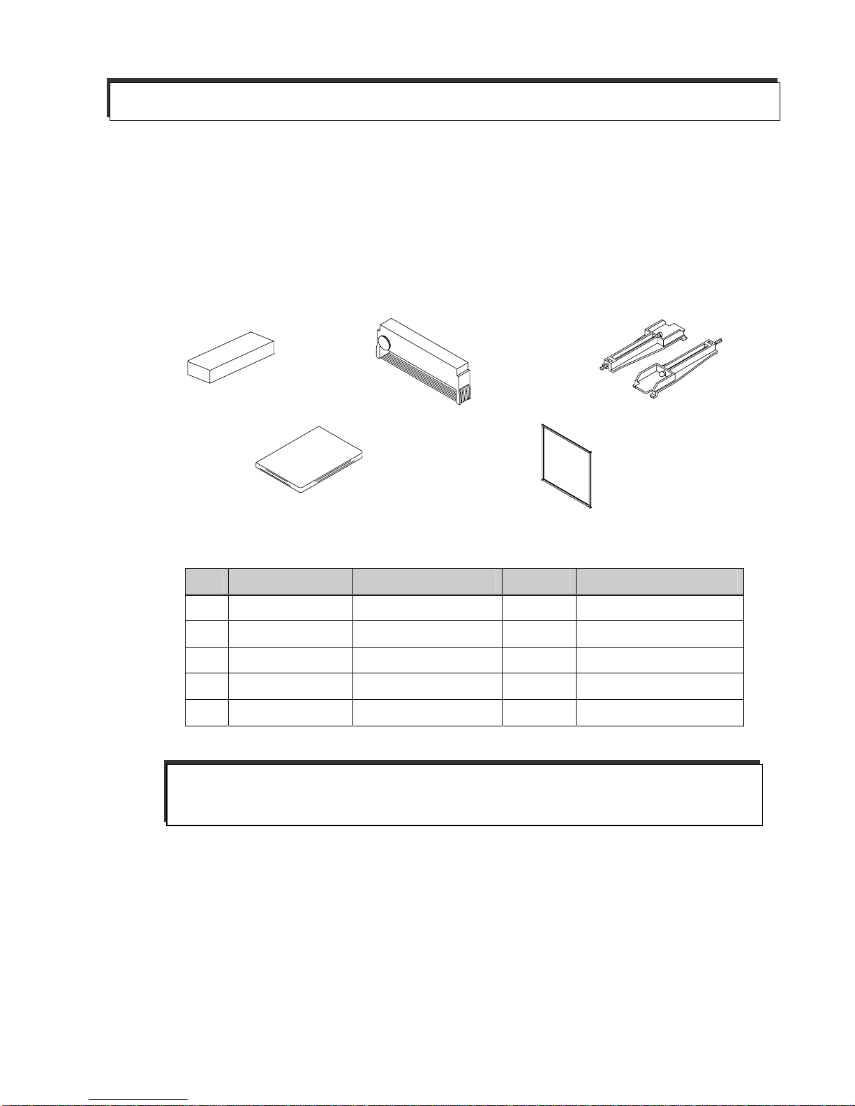
1.1 Checking theAccessories....................................................... 6
1.2 Checking the Model Type and Specifications........................ 7
1.3 Temporary Storage.................................................................. 8
1.4 Indication Card........................................................................ 8
2. CONSTRUCTION............................................................9
2.1 Appearance............................................................................. 9
2.2 Display Screen and Operation Keys.................................... 10
2.2.1 Display Screen ................................................................ 10
2.2.2 Operation Keys.................................................................11
3. INSTALLATION..............................................................12
3.1 External dimensions
and panel cutout....................................................................12
3.2 Mounting to the Panel...........................................................13
3.2.1 Procedure for Mounting to the Panel..............................13
3.2.2 Mounting to the Panel in compliance with the IP65.......14
4. WIRING ..........................................................................15
4.1 Terminal arrangement and Power Wiring.............................15
4.1.1 Terminal arrangement..................................................... 15
4.1.2 Power Wiring................................................................... 15
4.1.3 Wiring Procedure............................................................. 16
4.2 Input Wiring............................................................................17
4.2.1 Wiring Procedure............................................................. 18
4.3 DI function/Alarm Output Wiring (Option)............................. 20
4.3.1 DI function/Alarm Output Wiring Example .....................20
4.3.2Alarm Output Wiring Procedure......................................21
4.3.3 DI function Wiring Procedure..........................................21
4.4 Communication Wiring.......................................................... 22
4.4.1 RS-232C Wiring ..............................................................22
4.4.2 RS-485 Wiring.................................................................22
5. PREPARATIONS FOR OPERATION ...........................23
5.1 Setting the Chart Paper ........................................................23
5.2 Setting the Ribbon Cassette................................................. 29
6. RUNNING.......................................................................31
6.1 Running .................................................................................31
6.1.1 Status after Initial Screen ................................................ 31
6.2 Recording..............................................................................32
6.2.1 Recording Colors............................................................. 32
6.3 How to Record....................................................................... 32
6.3.1 Starting/Stopping Recording .........................................32
6.3.2 Feeding the Chart Paper.................................................32
6.3.3 Print Sample....................................................................33
6.4 Digital Print.............................................................................34
6.4.1 Manual Print.....................................................................34
6.4.2 List Print...........................................................................35
6.4.3 Engineering List Print......................................................37
6.5 Changing the Display ........................................................ 39
6.5.1Auto Display < >...............................................39
6.5.2 Manual Display < >..............................................39
6.5.3 Date Display < > .............................................. 39
6.5.4 Time Display < >.............................................. 39
6.5.5 Display Off < >...................................................... 39
7. DEVICE SETTING.......................................................40
7.1 Setting the Setup Mode.........................................................40
7.1.1 Setting the Range ............................................................43
(1) Setting method .................................................................43
(2) (Current/Voltage), (Thermocouple),
(Resistance Temperature Detector)..................44
(3) (Scaling)......................................................46
(4) (Square Root)..................................................48
(5) (Decade)......................................................50
(6) (Difference), (Sum),
(Average)........................................................52
(7) (Skip) ...............................................................53
7.1.2 Setting theAlarm..............................................................54
7.1.3 Setting the Unit.................................................................56
(1) Character Code Table......................................................57
7.1.4 Setting the Chart feed Speed..........................................58
7.1.5 Setting the Date and Time...............................................59
7.1.6 Copying the Setting Data.................................................60
7.1.7 Setting Other Functions...................................................61
(1) (Printing Cycle)............................................62
(2) (Zone Recording)............................................62
(3) (Partial Compression/Expansion)...................63
(4) (Digital Print)................................................64
(5) (Tag).....................................................................65
(6) (Comment Words)...........................................66
7.2 Setting the Engineering Mode...............................................67
7.2.1Alarm Hysteresis..............................................................70
7.2.2 Burnout ON/OFF..............................................................70
7.2.3 Channel Offset.................................................................70
7.2.4 Reference Junction Compensation.................................71
7.2.5 Changing the Printing Color ...........................................72
7.2.6 Settings Related to Recording.........................................73
(1) Trigger setting for recording start/stop.............................73
(2) Tag/channel print selection...............................................73
(3)Alarm print ON/OFF .........................................................74
(4) Logging print ON/OFF......................................................74
(5) Scale print ON/OFF..........................................................75
(6) Logging print Synchronous/Asynchronous .....................75
7.2.7 Setting the Communication Function..............................76
7.2.8 Initializing the Setup Data ..............................................76
7.2.9 DI functions.......................................................................77
7.2.10 Temperature Unit selection............................................77
7.2.11 Point Calibration.............................................................78
7.2.12 Data Calibration .............................................................79
7.3 Terminating the Engineering Mode.......................................81

5
8. COMMUNICATION......................................................82
8.1 General Description ..............................................................82
8.1.1 General Description of Functions................................... 82
8.1.2 Transmission Specifications............................................ 82
8.1.3 Data Structure..................................................................82
8.2 Opening/Closing the Link...................................................... 83
8.2.1 Open Command..............................................................83
8.2.2 Close Command .............................................................83
8.3 Outputting the Process Variable...........................................84
8.3.1 Specifying the Process Variable Output......................... 84
8.3.2 Updating the Data ...........................................................84
8.3.3 Specifying the Process Variable Data Output
Order (At BINARY Mode Output)..................................84
8.3.4 Outputting the Data......................................................... 84
8.3.5 Process Variable Transmission Format (ASCII) ............85
8.3.6 Process Variable Transmission Format (BINARY)........ 86
8.4 Outputting the Unit and Decimal Point Position Data..........87
8.4.1 Specifying the Unit and Decimal Point Position
Data Output....................................................................87
8.4.2 Updating the Data ...........................................................87
8.4.3 Outputting the Data......................................................... 87
8.4.4 Data Format..................................................................... 87
8.5 Outputting the Status............................................................. 88
8.5.1 Status Output Command ................................................88
8.5.2 Status Output...................................................................88
8.6 Data Reception Example...................................................... 89
9. MAINTENANCE.............................................................90
9.1 Inspection .............................................................................. 90
9.2 Cleaning................................................................................. 90
9.3 Replacing Consumables....................................................... 91
9.4Adjusting Dot Printing Position (Point Calibration)...............91
9.5 Calibration (Data Calibration)................................................91
(1) Calibration of Voltage ......................................................92
(2) Calibration of RTD (Resistance temperature detector).. 92
(3) Calibration of Reference Junction Compensation .........93
10. TROUBLESHOOTING................................................94
10.1 Troubleshooting ...................................................................94
10.1.1 Problems........................................................................94
10.1.2 When the Recorder Dose not Work at All.....................94
10.1.3 When there is a Major Error ..........................................95
10.1.4 When the Trend Recording is Deflected.......................95
10.1.5 When Nothing is Recorded ...........................................96
10.1.6 When Recording is Faint...............................................96
10.1.7 When the Chart Paper is not fed at All..........................97
10.1.8 When the Chart Paper is not fed Properly....................97
10.2 Self Diagnosis Function (ERROR)......................................98
10.2.1 Self Diagnosis Items......................................................98
10.2.2 Error Display...................................................................99
11. SPECIFICATIONS.....................................................100
11.1 Common Specifications.................................................... 100
11.1.1 Input Signal.................................................................. 100
11.1.2 Performance and Characteristics............................... 100
11.1.3 Structure ...................................................................... 101
11.1.4 Power Source.............................................................. 101
11.1.5 Normal Operating Conditions..................................... 101
11.1.6Alarm Output (Optional: LH6) ..................................... 102
11.1.7 Safety Standard and EMI Standard............................ 102
11.1.8 DI Function (Option : RE6).......................................... 102
11.1.9 Paper-empty Detection Function (Option: FL)........... 102
11.2 Standard Specifications..................................................... 103
11.2.1 Measurement Range .................................................. 103
11.2.2 TheAccuracy at the Computation .............................. 106
(1) Scaling........................................................................... 106
(2) Square root computation............................................... 106
(3) Decade........................................................................... 107
(4) Difference, Sum, andAverage...................................... 107
11.2.3 Individual Specifications.............................................. 108
11.2.4 Standard Functions..................................................... 109
11.3 Standard Setting Functions................................................110
11.3.1 Standard Setting Functions..........................................110
11.4 Optional Functions.............................................................110
11.4.1 Remote Function of DI.................................................110
11.4.2Alarm Output function...................................................110
11.4.3 Communication unit .....................................................110

6
1. INTRODUCTION
1.1 Checking the Accessories
Upon delivery of this instrument, unpack and check its accessories and appearance.
If there are any missing accessories or damage to the appearance of the instrument, please contact our
dealer where you purchased the instrument, or our sales representative.
The following accessories are included with the recorder.
1. Chart paper 2. Ribbon cassette 3. Mounting bracket
4. Instruction manual 5. Packing
Fig. 1.1 Accessories
Table 1.1 List of Accessories
No. Part Name Type Quantity Remarks
1 Chart paper H-10100 1 100 equal divisions
2 Ribbon Cassette WPSR188A000001A 1
3 Mounting bracket H4A14175 2 Panel mounting bracket
4 Instruction manual HR71E 1 This manual
5 Packing H4H14900 1 For IP65
[Note]
The ribbon cassette has been set in the instrument upon shipment.

7
1.2 Checking the Model Type and Specifications
Anameplate has been secured on the inside of the instrument. Remove the chart holder and
make sure that the nameplate is put in the middle far side of the instrument.
Make sure that this instrument meets your requested specification, checking the following table.
Table 1.2 Model type
H R – 7 0 6, 144(W) x 144 (H) x 150 (D)mm
Measuring point 6 6 points
C5 Communication function (RS-485)
RE6 DI function
FL Paper-empty detection function
Options
LH6 Alarm output function

8
1.3 Temporary Storage
Store the instrument in the following environment.
When installed within another machine, ensure that the operating environment conforms to the
following conditions.
1.4 Indication Card
An indication card has been affixed to the door upon delivery. Enter a name as required.
CAUTION
Storage in a poor environment may damage the appearance, functions, and service life of the
instrument.
Storage Environment
•Aplace free from excess dust
•Aplace free from combustible, explosive, or corrosive gases (SO2, H2S, etc.)
•Aplace free from vibrations or shocks
•Aplace frees from water or steam or high humidity (95% RH max.)
•Aplace free from direct sunlight or high temperature (50 max.)
•Aplace free from an extremely low temperature (-20 min.)
CAUTION
Note that if a non-approved nameplate is attached, it may damage the door or mounting part.

9
2. CONSTRUCTION
2.1 Appearance
Fig. 2.1 Appearance
Ribbon cassette
Door
Chart holder
Display keyboard
Terminal block
Printer
Case
Mounting bracket
Indication card

10
2.2 Display Screen and Operation Keys
2.2.1 Display Screen
The following describes the display screen. Since the channel numbers and data are indicated by a
7-segment LED, alphabets are symbolized to represent them.
For the LED display, see "SymbolizedAlphabets for Display" at [Reference] below.
Fig. 2.2.1 Display
[Reference] Symbolized Alphabets for Display
Display
Alphabet A B C D E F G H h I J K L l
Display
Alphabet M N O P Q R S T U V W X Y Z
Alarm Type Display
Indicates an alarm type in red.
"H" is lit when the alarm is High. And
“L” is lit when the alarm is Low.
Neither of them is lit when there is no
alarm.
Channel No. Display
Indicates channel
number in orange.
Data Display
Indicates the process
variable, time, setting
screen, etc. in orange.
Operation Keys
Use these keys for setting and
other operations.
Status Display
The "REC" lamp (orange) is lit when
recording. The "ALM" lamp (red) is lit while
the alarm is being activated.
denotes that the lamp goes out, and
denotes that it is lit.

11
2.2.2 Operation Keys
The following describes functions of each operation key.
The actual operation keys are described as shown below.
Fig. 2.2.2 Operation Keys in this manual
Table 2.2.2 Names of Operation Keys and Their Functions
Key Name Function
“REC” key
Starts/stops recording.
To stop, press the “REC” key for 3 seconds or longer.
(The “REC” lamp goes out.) To start, press the “REC” key.
(The “REC” lamp lights.)
“MENU” key MENU function Selects engineering list print and changes the mode
to the setting mode.
“ESC” key ESC function While selecting a function, exits that menu without
finishing.
“PRINT” key PRINT function Used to perform manual print or list print.
“” key function Used to select a setting parameter (numeral or
built-in command) (ascending direction).
“FEED” key FEED function The chart paper is fed while the key is pressed, and
stopped when released.
““ key function Used to shift a digit in setting anumeral.
“ENT” key Used to register a setting parameter (numeral or built-in command) after
selecting it, or executing a function. Pressing this key executes the setting.
REC
ESC
MENU
PRINT
FEED
ENT
REC PRINT FEED ENT
ESC
MENU

12
3. INSTALLATION
3.1 External dimensions and panel cutout
Fig. 3.1 External dimensions and panel cutout
CAUTION
For the maintenance and safety of the instrument, spaces larger than the size written in the bracket
( ) should be secured to unit.
Dimension required
when the door is full
y
open (135 degrees).
(Wall on the left side).
Unit: mm <Front> <Rear>
<Side> <Panel Cutout>
137
137
(128)
(128)
7 max
(Pannel thickness)
25 150
(56)
144
144 3.5
2.5
(100)
200 min.
200 min.
138
+1
-0
138+1
-0
LN
1A 2C2A1C 3A 4C4A3C 5A 6C6A5C
4+
B
4-
B
4
A5+
B
5-
B
5
A
6+
B
6-
B
6
A
1+
B
1-
B1
A2+
B
2-
B2
A
3+
B
3-
B
3
A
SG
RDTD
+
-
DI
COM
DI
3
DI
2
DI
1

13
3.2 Mounting to the Panel
3.2.1 Procedure for Mounting to the Panel
1) Assemble the mounting bracket, referring to Fig.3.2.1-1.
2) Insert this instrument through the front of the panel.
3) Hook the claws of the mounting bracket at the square holes on the top and bottom surfaces of
the case.
4) Tighten the screw of the mounting bracket with a screwdriver to attach it to the panel. When
the mounting unit does not move back and forth any more, tighten the screw by 180 .
Fig. 3.2.1-1 Mounting bracket
[Note]
If it is tightened with an excessive force, the case may be distorted and the mounting bracket may be
defaced.An adequate tightening torque is about 0.2 to 0.3 N・m (2 to 3 kgf・cm).
WARNING
Do not install the instrument in a place exposed to combustible, explosive, or corrosive gas (SO2,
H2S, etc.).
CAUTION
Install the instrument in the following places
•Aplace without rapid humidity change.
•Aplace of normal temperature (around 25 ).
•Aplace exposed to as little mechanical vibrations as possible.
•Aplace with as little dusts as possible.
•Aplace affected by the electromagnetic field as little as possible.
•Aplace not directly exposed to high radiant heat.
•Aplace where the altitude is up to 2000m.
• Humidity has an effect on the chart paper and ink. Use the instrument in a humidity range of
20 to 80%RH (60%RH is the optimum).
• This instrument needs the inside installation.
Mounting to the Panel
•Asteel plate not thinner than 1.2mm is recommended as a mounting panel.
• The maximum thickness of the mounting panel is 7mm.
Inclination
• Install the instrument horizontally.
• The instrument should be installed so that its inclination should be 0 at the front and within 30 at
the rear.
A
ssemble in such a manne
r
that the screw nose will be
almost aligned with the plate
surface. Mounting Claw
Body
Mounting Claw

14
Fig. 3.2.1-2 Mounting to the Panel
3.2.2 Mounting to the Panel in compliance with the IP65
Prior to mounting the instrument to the panel, attach a packing to the position shown in the figure.
The rest of the procedure is the same.
Fig. 3.2.2 Mounting to the Panel (in compliance with the IP65)
Mounting of Packing
Packing
Panel
Mounting bracket
Packing
Panel
Screw
Panel
Mounting bracket
Screw

15
4. WIRING
4.1 Terminal arrangement and power wiring
4.1.1 Terminal arrangement
Fig. 4.1.1 Terminal arrangement (Rear view)
4.1.2 Power Wiring
Power source
terminal block
Communication
terminal block (RS-232C)
Input terminal block
A
larm output terminal block
(Option: LH6) Communication
terminal block (RS-485)
(
O
p
tion: C5
)
DI terminal block
(Option: RE6)
LN
1A 2C2A1C 3A 4C4A3C 5A 6C6A5C
4+
B
4-
B
4
A
5+
B
5-
B
5
A
6+
B
6-
B
6
A
1+
B
1-
B
1
A
2+
B
2-
B
2
A
3+
B
3-
B
3
A
SG
RDTD
+
-
DI
COM DI
3DI
2
DI
1
WARNING
(1) In order to prevent an electric shock, be sure to provide protective grounding prior to the powe
r
supply to the instrument.
(2) Do not cut the protective grounding conductor or disconnect protective grounding.
(3) Make sure that the supply voltage for the instrument conforms to the voltage of the suppl
y
source.
(4) Attach a transparent protective cover prior to switching on power to the instrument.
(5) Any interruption to the protective conductor inside or outside the instrument or disconnection
of the protective grounding terminal is likely to make the instrument dangerous under faul
t
conditions. Intentional interruption is prohibited.

16
4.1.3 Wiring Procedure
(1) Put your fingers on the left and right (both sides) hooks of the transparent protective cover on
the power source terminal block. Pushing them inside, pull out the cover toward you.
(2) Connect the power source electric wire, referring to Fig. 4.1.3. Connect the protective
grounding to the terminal. Connect the non-grounding side of the power source to "L"
terminal. Connect the grounding side to the "N" terminal.
(3) Attach the transparent protective cover.
(4) Make sure that protective grounding is properly done.
Fig. 4.1.3 Power source Terminal block
LN
CAUTION
(1) As an electric wire for the power source, use a 600V vinyl insulated wire (IEC 227-3) or its
equivalent or above.
(2) Attach a round solderless terminal with an insulation sleeve (for M3.5) to the end of the electric
wire.
(3) Connect a protective grounding (resistance: 100 or lower, a minimum diameter of a
grounding conductor: 1.6mm) to the protective grounding terminal.
(4) If another instrument shares the protective grounding conductor, there may be an effect
caused by noise coming from the grounding conductor. Do not share the grounding conductor
with other instruments.
(5) In order to comply with the requirements of safety standard EN61010, the recorder should
have one of the following as a disconnecting device, fitted within easy reach of the operator,
and labeled as the disconnecting device.
a. A switch or circuit breaker which complies with the requirements of IEC60947-1,
IEC60947-2 and IEC60947-3.
b. A separable coupler which can be disconnected without the use of a tool.
c. A separable plug, without a locking device, to plug in a socket outlet in the building.
(6) This product has been designed to conform to IEC1010-1 installation Category and pollution
degree 2.
CAUTION
For the transparent protective cover, remove the left and right (both sides) hooks simultaneously.
If they are removed in turn, the cover may be damaged.

17
4.2 Input Wiring
CAUTION
(1) Precautions for the input electric wire
• Make sure that no noise is mixed in input wiring. For input wiring, a shielded wire or twisted wire
effective for noise should be used.
• In the case of thermocouple input, connect a thermocouple wire directly or use a compensating
lead wire. A shielded input line should be used.
• In the case of RTD (resistance temperature detector) input, dispersion of 3-wire line resistance
should be lower than the values mentioned below. Ashielded input line should be used.
For Pt 100, JPt 100; 50m max.
• When it is likely to be affected by induction noise, particularly when wiring near the
high-frequency power source, a shielded twisted wire should be used.
• Attach a round solderless terminal with an insulated sleeve (for M3.5) to the end of the electric
wire.
(2) Precautions for wiring
• The wiring between the instrument and measurement point should be kept awayfrom the power
circuit (25V or higher circuit or DO circuit).
• Short-circuit unused input terminals. (Short-circuit between "+" and "-" in the case of mV, V, or
thermocouple input, and short-circuit among A, B, and B in the case of RTD input.)
• Be sure to ground the connecting wire shield.

18
4.2.1 Wiring Procedure
(1) Put your fingers on the left and right hooks of the transparent protective cover on the input
terminal block. Pushing them inside, pull out the cover toward you.
(2) Wire the input lines, referring to Fig. 4.2.1-1 (P.18), Fig. 4.2.1-2 and Fig. 4.2.1-3. (P.19)
(3) Attach transparent protective covers.
Fig. 4.2.1-1 Input Wiring (For mV, V and Thermocouple inputs)
LN
1A 2C2A1C 3A 4C4A3C 5A 6C6A5C
4+
B
4-
B
4
A
5+
B
5-
B
5
A
6+
B
6-
B
6
A
1+
B
1-
B
1
A
2+
B
2-
B
2
A
3+
B
3-
B
3
A
SG
RDTD
+
-
DI
COM DI
3DI
2
DI
1
LN
1A 2C2A1C 3A 4C4A3C 5A 6C6A5C
4+
B
4-
B
4
A
5+
B
5-
B
5
A
6+
B
6-
B
6
A
1+
B
1-
B
1
A
2+
B
2-
B
2
A
3+
B
3-
B
3
A
SG
RDTD
+
-
DI
COM DI
3DI
2
DI
1
Shielded wire
Shielded wire
(+)(-)(+)(-)
Ground Ground
DC voltage input Thermocouple input
Connecting lead wire Connecting compensating lead wire
Input
terminal
block
CAUTION
For the transparent protective cover, remove the left and right (both sides) hooks simultaneously.
If they are removed in turn, the cover may be damaged.

19
LN
1A 2C2A1C 3A 4C4A3C 5A 6C6A5C
4+
B
4-
B
4
A
5+
B
5-
B
5
A
6+
B
6-
B
6
A
1+
B
1-
B
1
A
2+
B
2-
B
2
A
3+
B
3-
B
3
A
SG
RD
TD
+-
DI
1
DI
2
DI
3
DI
COM
BBA
Shielded wire
3-core cord
(Identical wire diameter and length)
Ground
RTD (Resistance temperature detector)
Input terminal block
LN
1A 2C2A1C 3A 4C4A3C 5A 6C6A5C
4+
B
4-
B
4
A
5+
B
5-
B
5
A
6+
B
6-
B
6
A
1+
B
1-
B
1
A
2+
B
2-
B
2
A
3+
B
3-
B
3
A
SG
RD
TD
+-
DI
1
DI
2
DI
3
DI
COM
(+) (-)
Shunt resistor
Connecting lead wire
DC current input
Input terminal block
Shielded wire
Ground
Fig. 4.2.1-2 Input Wiring (For RTD)
Fig. 4.2.1-3 Input Wiring (For mA input)
CAUTION
(1) Attach a shunt resistor to the input terminal block of the instrument.
(2) A shunt resistor affects input accuracy. Use the following resistor.
Resistance: 250 , Rated power: 1/4W, Tolerance: 0.1% max.
Temperature coefficient: 50ppm max.
Other manuals for HR-700
2
Table of contents
Other Shinko Voice Recorder manuals