Shire Forget - Me - Not Arbour Manual

Version 01 Sasha Leney 23/11/2020
These instructions are for your safety. Please read through them thoroughly before use.
PLEASE KEEP THIS LEAFLET FOR FUTURE REFERENCE
© Forget-Me-Not Arbour
Mass: 52.2 kg Batch No: XXXX

Let’s
get started...
GB
IE
Important information...
Safety 03
Preparation of base 04
Warranty 04
Care, maintenance & Recycling 05
customerservice@shiregb.co.uk
Brigstock Road Wisbech Cambridgeshire PE13 3JJ
Tel 01945 465 295
F Pour obtenir un exemplaire des instructions ou une copie dans une autre
langue s'il vous plaît envoyez un e-mail ou écrire à l'adresse ci-dessous.
PL Na kopii instrukcji lub kopii w innym języku prosimy o wysłanie maila
lub pisaćna adres podany poniżej.
RUS
Для получения копии инструкции или копия на другом языке,
пожалуйста, отправьте по электронной почте или написать по
указанному ниже адресу.
TR Başka bir dilde talimatlarıveya bir kopyasınıbir kopyasıiçin bir e-posta
gönderebilir veya aşağıdaki adrese yazınız.
EN For a copy of the instructions or a copy in another language please send
an email or write to the address below.
I Per richiedere una copia del libretto di istruzioni, in italiano, o in un’altra
lingua, per favore, invia una e-mail o scrivi a l’indirizzo sottostante.
02
In more detail...
Parts List 06
Fascia & Nail List 07
Detailed Technical Drawing 08-09
Hardware Chart 10
Before you start 11
Assembly Instructions 12-24

We advise the use of non slip protective gloves throughout
the assembly process.
We advise the use of steel capped protective footwear
throughout the assembly process.
We advise the use of protective headwear and safety
goggles throughout the assembly process.
Where a ladder is in use another person must hold the
ladder.
Do not attempt to work in windy conditions.
We advise the use of a scaffold tower when fitting the roof
for felting or if you cannot reach from the ground.
Do not allow children near the tools and work area.
Follow any safety precautions quoted by the manufacturer
for any equipment you use.
We advise that you use a helper to hold the glass in position
whilst you nail the beading in place.
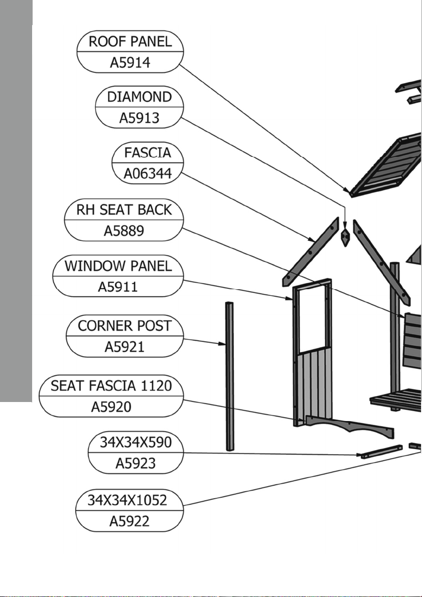
Check all parts before assembly.
Only use child and animal safe wood preservative.
Do not use creosote.
Allow the wood preservative to fully dry before use.
Regularly check the building for wear and tear.
Getting Started…..
GB
IE
EVERY PRECAUTION IS TAKEN TO ENSURE THAT YOUR BUILDING HAS NO
ELEMENT INCORRECTLY PLACED OR POSSIBLY HAZARDOUS, HOWEVER
PRIOR TO USE PLEASE CHECK ALL SURFACES FOR THE FOLLOWING:
(1) RAISED GRAIN, SPLINTERS: Sand down timber to smooth finish
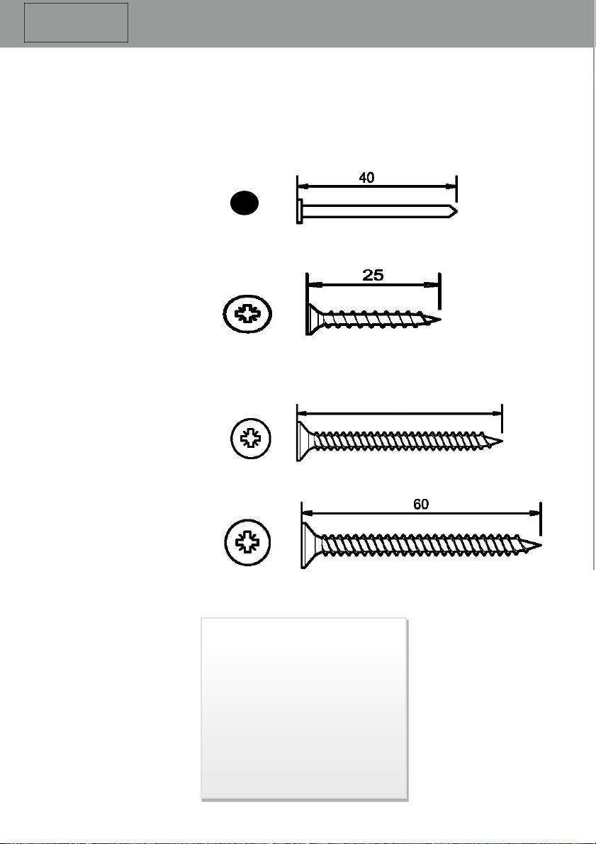
(2) NAIL/SCREW/PIN HEADS PROUD: Tap home to be flush with surface of
timber.
(3) DAMAGED SCREW HEADS RESULTING IN SHARP SPLINTERS OF
METAL: Replace.
(4) SHARP ENDS OF NAILS/ SCREWS/ PINS PROTRUDING THROUGH THE
PANEL: Remove and Reposition.
(5) ENSURE ALL PARTS ARE SECURED AGAINST REASONABLE FORCE:
Remove and Refit.
(6) ENSURE THERE ARE NO LOOSE PARTS: Remove and Refit/Discard.
Important!
Safety
IMPORTANT ! For your safety please read
carefully the safety warnings
Check that you have noted all the following instructions:
03

Getting Started…..
GB
IE
Base and Warranty
The following are also excluded:
Damage resulting from poor assembly.
Poor treatment application.
Poor care and maintenance.
Changes to the design.
Misuse.
General wear and tear.
Warranty...
10 Year anti-rot warranty subject to the following:
The building must be raised so it is not in contact with any water
retaining base surface (for example grass).
This can be achieved using a timber, concrete or slab base.
When using a concrete or slab base use damp proofing strips
under the bearers.
The building must have been completely treated and sealed
immediately prior to assembly.
The building must have been re-treated and re-sealed annually.
NOTE: Wood is a natural product, and therefore the following are
excluded from the warranty:
- Colour change.
- Warping.
- Splitting.
Preparation of base...
We recommend that the base onto which your building will stand should be at least
75mm larger in each direction than the total floor size of the building.
Actual floor area of the building: 1236mm x 654mm
Total height clearance: 2161mm
Roof size: 1424mm x 722mm
The chosen position in your garden for your building should be excavated to a depth
of 75mm to allow a base of sand, onto which paving slabs can be evenly laid.
You may also use an adjustable timber base or a concrete base. Whatever base you
decide upon IT MUST BE LEVEL AND FIRM.
04

Care, Maintenance and Recycling
1. Pallet and timber widely recycled.
2. Cardboard widely recycled.
3. Plastic strapping subject to local regulations.
4. Plastic sheeting subject to local regulations.
(1) Visually check for weather damage.
(2) Check and replace if necessary any silicone sealant if used on your
building.
(3) Check the roofing material for wear.
(4) The doors and windows may require periodical adjustment.
(5) Ensure your building is well ventilated especially during hot weather.
(6) During extremely hot periods, humidify your building to prevent the timber
from drying out.
The 5 golden rules of care:
The 6 golden rules of maintenance:
1. Timber widely recycled.
2. Metal fixings widely recycled.
3. Glass widely recycled.
packaging
Building
(1) Ensure your base is level and firm.
(2) Ensure the building is not sitting directly on the ground using damp proof
membrane or the optional timber base.
(3) Ensure every piece of timber and surface, especially that is hidden upon
assembly, is treated with a top quality wood preservative at least twice
(before assembly). Turn the panels upside down whilst painting so the
treatment runs into the seams.
(4) Garden buildings are not waterproof, therefore we recommend you seal
between all the panels with a silicone based sealant.
Getting Started…..
GB
IE
05
Recycling and disposal:

Stacked Parts List
Description
(part No ) - Qty
06

Fascia and Nail Bag Parts List
Description
(part No ) - Qty
07

In more detail…..
GB
IE
08

In more detail…..
GB
IE
09

Hardware Chart
Scale 1:1
(A0035) x 45
60mm Posi-Drive Screw
Nail bag contents
Building
Photographs
It will be greatly
appreciated if you could
forward images of your
completed building to -
Description
(part No ) - Qty
10
(A0032) x 03
25mm Posi-Drive Screw
(A0032) x 09
40mm Posi-Drive Screw
40
(A0025) x 14
40mm Round Head Nail

11
Before you start...
Things to check before you start:
Check all parts as listed in the parts lists.
Read the instructions fully before starting work.
Follow all the health and safety guidelines.
Ensure your base is ready – See page 4.
You will need:
Hammer
Spirit level
Ladder
1mm + 5mm drill bit
Drill
Tape measure & Ruler
Sand paper
Gloves
Saw
Pencil
Goggles
A helper for some
tasks
Screwdriver
Sharp knife
Masking tape
When you see the drill icon
Only ever drill through the first
piece of framework which will be a
pilot hole for the screw to attach the
second piece of framework
The required drill bit size is
shown with the icon.
5mm
In more detail…..
GB
IE

GB-IE
01
Assembly instructions:
These instructions are for your safety. Please read through them thoroughly before use.
Treat all the parts before assembly – see page 5!
GB-IE The “Panel layout” is showing you how to position the panels.
The Panels FIT INBETWEEN THE CORNER POSTS!
Plain Panel
(A06342)x01 Panel Layout
A5912
Drill the Plain Panel (A06342) as above.
12
5mm
NOTE
Some holes
drilled for
later use
A06342
If using a drill or
electric screwdriver
carefully but firmly
push the opposite end
to the screwdriver bit
into the screw head and keep the
pressure on to prevent the
screwdriver spinning in the screw.
A5911
A5911
A5921 A5921
A5921
A5921

GB-IE
Lay the Plain Panel (A06342) flat.
Screw two Corner Posts (A5921) to the sides as below, using 6x 60mm Screws (A0035)
within the pilot holes drilled in the previous step.
02
13
60mm Screws
(A0035)x06
Step 1
(A06342)x01
Corner Post
(A5921)x02
Flat edge sits flush with outside cladding.

GB-IE
Drill one Window Panel (A5911) as below. Making sure the outside cladding is facing inwards
and flush with the flat face of the corner post, fix with 3x 60mm Screws (A0035) using the
pilot holes previously drilled. Then screw another Corner Post (A5921) as below, using the
pilot holes. NOTE: Orientation of the Corner Posts.
14
03 5 mm
60mm Screws
(A0035)x06
Window Panel
(A5911)x01
Corner Post
(A5921)x01
Sits flush with post
NOTE
Some holes
drilled for
later use
Sits flush with cladding

GB-IE
Drill the other Window Panel (A5911) as below. Place the panel making sure the cladding is
facing inwards and is flush with the corner post. Fix with 3x 60mm Screws (A0035). Then fix
the last Corner Post (A5921) to the window panel using 3x 60mm Screws (A0035) within the
pilot holes. NOTE: Orientation of the Corner Posts.
04
15
60mm Screws
(A0035)x06
5 mm
Window Panel
(A5911)x01
Corner Post
(A5921)x01
Sits flush with post
NOTE
Some holes
drilled for
later use
Sits flush with cladding

16
GB-IE
Measure and mark from the bottom of the Window Panels up 368mm. Drill and screw the two
34x34x590 (A5923) so that the top of the timber sits flush at the 368mm mark as below. Drill
and screw the 34x34x1052 (A5922) to the Plain Panel so that the top is flush with the
34x34x590 timber. Fix all with 40mm Screws (A0033) in each side.
05
34x34x1052
(A5922)x01
34x34x590
(A5923)x02
5mm
40mm Screws
(A0033)x09
40

17
GB-IE
Drill through the seat frame made in Step 05 as below. Carefully stand the building up and
place the Seat Base (A5912) onto the frame as below. Make sure the 12mm overhang on the
seat base is facing forward. Secure the base using 7x 60mm Screws (A0035) using the pilot
holes drilled.
06
5mm
Seat Base
(A5912)x01
60mm Screws
(A0035)x07
Drill through the seat frame
12mm
overhang

GB-IE
Place the RH Seat Back (A5889) onto the Seat Base as below. Drill and screw through the
Window Panel so the screws go into the side bar of the Seat Backing.
Measure and mark on the Plain Panel where the middle bar of the seat back sits. Then drill
and screw using 2x 60mm Screws (A0035).
07
18
5mm
RH Seat Back
(A5889)x01
60mm Screws
(A0035)x06
Drill and Screw
through the
window panel
into the side bar
of the Seat Back
Drill and Screw
through the plain
panel
into the middle
bar of the Seat
Back

19
GB-IE
Place the Gable (A06343) onto the Plain Panel as below. Make sure the cladding is facing
inwards and is flush with the cladding on the Plain Panel. Make sure the gable is central and
equal on both sides.
Fix through the plain panel as below using 2x 60mm Screws (A0035).
08 5mm
Gable
(A06343)x01
60mm Screws
(A0035)x02
Sits equal both sides

Drill both Roof Panels (A5914) as below. Fix the 44x44x722 (A5924) to the top of one roof
panel as below, make sure the edge is flush with the roof panel frame work. Fix with 3x 60mm
Screws (A0035). Fix the second roof panel with 3x 60mm Screws (A0035) as below. The
44x44x722 piece of timber should not be visible once both panels are fixed.
09
GB-IE
20
Roof Panel
(A5914)x02
5mm
44x44x722
(A5924)x01
X2
60mm Screws
(A0035)x06
Other manuals for Forget - Me - Not Arbour
1
Table of contents
Other Shire Patio Furniture manuals
Popular Patio Furniture manuals by other brands

Greemotion
Greemotion GM-3003 quick start guide

Simply Shade
Simply Shade Ibiza SSUWA811SS instruction manual

Courtyard Creations
Courtyard Creations RUS496W Assembly instructions

Kettler
Kettler VANCOUVER operating instructions

Blooma
Blooma Kiwi 3663602936701 Assembly instructions

LAZBOY
LAZBOY 780-01291193-9 owner's manual