Shivaki SHPC-0915E User manual
PortableAir Conditioner
Instructions Manual
Model:
SHPC-0915E
Capacity:
9000 BTU/hour
This manual contains important information and recommendations that
weask y ou to follow to ensurethe qualityand continuous operation of
y our air conditioner.
Thank you.

CONTENTS
SAFETY INSTRUCTIONS...................................................................................1
IDENTIFICATION ........................................................................................... 2
ASSEMBLY...................................................................................................... 3
CONTROL PANEL .......................................................................................... 5
REMOTE CONTROL............................................................................................5
OPERATION MODES...................................................................................... 6
WATER DRAINAGE ...................................................................................... 7
MAINTENANCE...................................................................................................8
MAINTENANCE ..................................................................................................9
END OF SEASON STORAGE ...................................................................... 10
TROUBLESHOOTING .................................................................................. 10
FAILT CODES, REMEDIAL MEASURES ................................................. 11
Due to the our improvement policy, the device’s parameters, dimensions, performance and quality are subject to
change without notice.

1
SAFETY INSTRUCTIONS
Please read these Instructions carefully.
Use this device in strict accordance with these
instructions. Please be informed that not each
and every situation or operational condition
may be foreseen by the instructions. Use
common sense and be careful when using,
installing or maintaining the device.
If the device is used in unvented rooms, take
measures to prevent the refrigerant gas
leakage, as it entails a risk of fire
The packaging material can be recycled.
Contact a recycling center to dispose of the
worked-out device.
Make sure that no air enters the refrigerant
system and check for refrigerant leaks after
the air conditioner has been moved.
Do not remove the plug from the outlet when
the device is turned on, as this may cause arcing
and create a fire hazard.
After installing the air conditioner run test
duty cycle and record its operating
performance.
You can only use the air conditioner with
fuses that suit maximum power supply current
capacity or other similar protective devices.
The device must be disconnected from the
power supply during idle time, cleaning,
maintenance or repair.
Maintain proper temperature conditions to
protect the device from harm
Make sure that the mains voltage
corresponds to the voltage declared in the
passport of the device. Both switch and
power plug must be kept clean. Insert the
plug into the socket properly to avoid electric
shock or fire due to poor contact.
Make sure that the plug fits the socket, use
another socket if not.
Flammable liquids (alcohol, etc.) and
cylinders under pressure (eg, aerosol cans)
must be kept at a distance of at least 50 cm
away from the device.
Remote control batteries must be disposed of
properly.
Do not leave doors or windows open while the
device is operating
Protect the device from contact with water.
Electrical isolation could be damaged leading to
an electrical shock.
Do not allow children to play with the device.
if you ever find the power cord damaged,
contact the manufacturer or its agent to replace
it, because a damaged power cord can cause a
fire or give you an electrical shock.
2
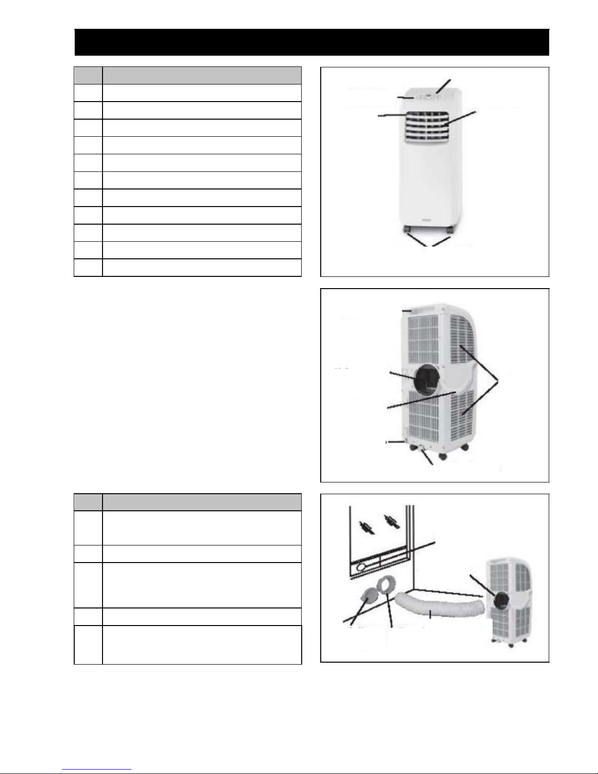
IDENTIFICATION
No.
Item
1
Clip-on adaptor for easy and secure installation of
air duct
2
Air Outlet duct
3
Telescope window kit- for filling the open
window space Including hole for connection to
air outlet duct
4
Round connector
5
Round connector cap
No.
Item
1
Control panel
2
Air outlet
3
Signal receiver
4
Adjustable airflow
5
Transport handle
6
Caster wheels
7
Drain port
8
Power cord
9
Air filters
10
Exhaust outlet
11
C-Shape clamp
3. Signal receiver
1. Control panel
4. Adjustable airflow
2Air outlet
6 Caster wheels
Rear view
5. Transport handle
3. Telescope window kit
1. Control panel
7. Drain port
1. Clip-on adaptor
8. Power cord
11. C-Shape clamp
10. Exhaust outlet
9. Air filters
5. Round
connector cap
4. Round
connector
2. Air Outlet duct
3
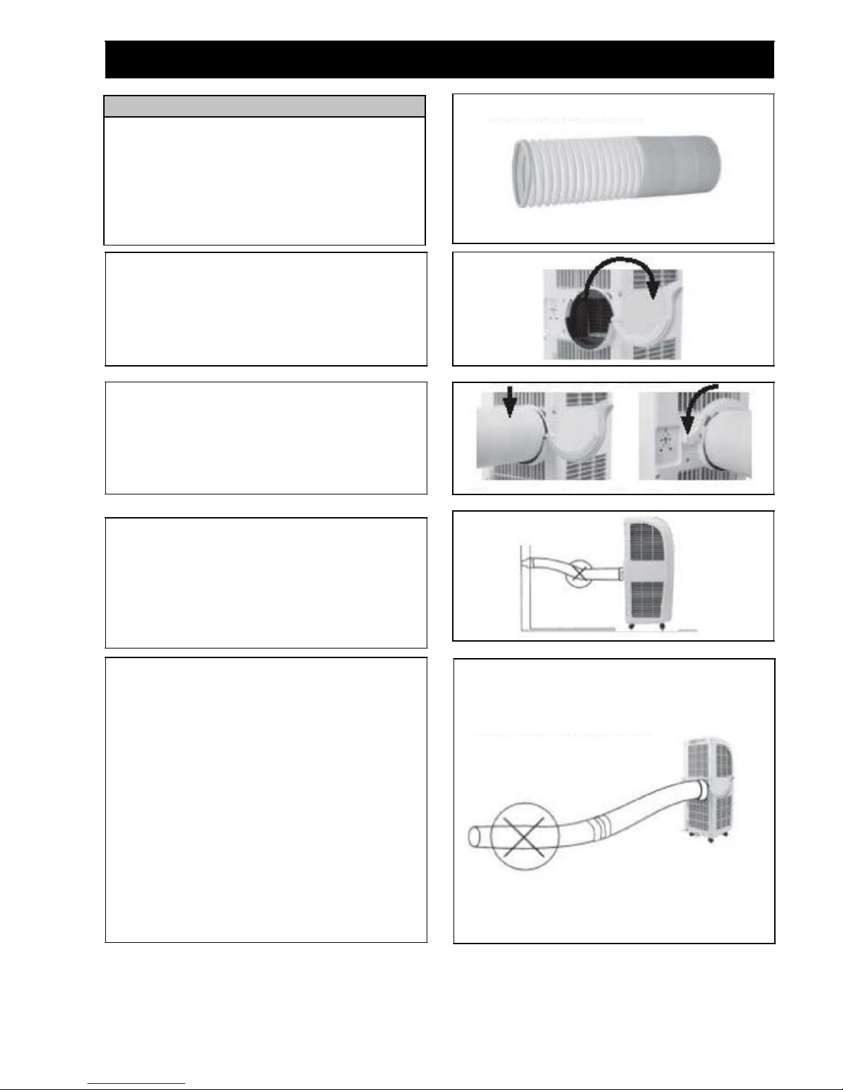
ASSEMBLY
Fitting the air outlet duct
This air conditioner is required to have the air outlet
duct fitted to an external opening to exhaust the hot air.
The duct can be extended from 390mm to 1500mm
long, however it is recommended to use the shortest
possible length.
•
Pull the end of the air outlet duct apart by several
turns
•
Open the C-shape clamp from dosed position
•
Insert the pulled apart and of the air outlet duet into
the exhaust outlet and dip the C-shape clamp to fit
the air outlet duct In position.
Prevent any bow or bend In the middle of the duct, as
this will trap hot exhaust air, which will radiate Into
the room and cause the unit to shut off automatically
(due to overheating).
IMPORTANT: The duct length hat been
specifically designed for this product. Do not replica
or lengthen the duct with attachments. If the venting
of the exhaust air is inhibited in any wary the unit may
over heart and shut off.
The location may be either a temporary or permanent
type depending on your requirement. If you wish to
frequently move the unit from room to room without
creating a permanent opening in a wall or window,
you can use the temporary location kite as described
below under temporary location.
If you wish to have a place set aside where you can
connect and operate the unit on a continuous basis you
can use the round connector, as described below under
permanent location.

4
ASSEMBLY
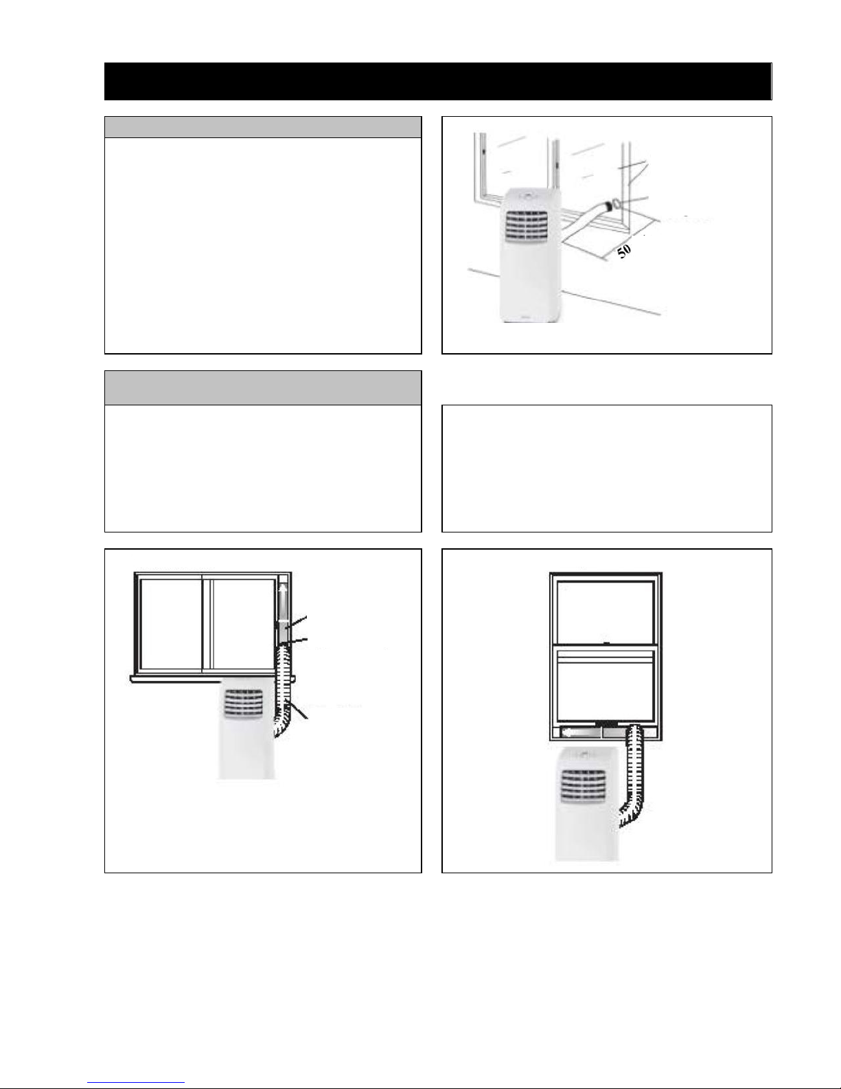
Permanent Location
The round connector (Item 4) may be fitted into a
circular opening cut into a wall or glass window.
This connector, when not in use, can be left in
position with the opening covered by the cap
provided.
Temporary Location:
Sliding Window (Horizontal/Vertical)
1.Side window open
2.Insert adjustable window kit into opening,
telescope window kit to fit window.
3.Insert screw into closest available hole in edge
of kit to hold the position.
4. Screw window kit adaptor onto flexible
duct.
5.Screw air conditioner adaptor onto other end of
flexible duct 0L Insert window kit adaptor into
window kit and clip Into place.
6.Slide air conditioner adaptor down into rails to
secure it to air conditioner exhaust.
7.Partially close window to secure window kit.
8. Your appliance is ready for use.
Solid Wall Of
Window
Round Window
Connector
Vertical sliding window
Sliding Window
Telescope
window
kit
Round Connector
Air Outlet duct
сm
5
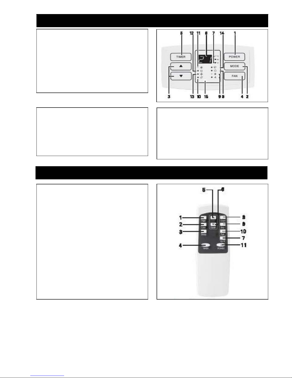
CONTROL PANEL
1. POWER button: press this button to turn the unit
on/off.
2. MODE button: press this button to select Cool,
Dry or Sleep mods
3. UP & DOWN button: press thorn buttons to sat
room temperature or time for the TIMER mode.
4. RAN button: press this button to increase or
decrease fan speed for Cool and Fan mode only.
5. TIMER button: press this button to oat timer
On/off.
6. Seven segment display: display room
temperature, sat temperature in Cool and Fan
mode, an time in timer or/off mode.
7. Press the UP & DOWN button simultaneously to
switch between the Fahrenheit end Celsius
degrees.
14.
8. Timer on/off light Indicator
9. Fan speed light Indicator
10. Water full tight Indicator
11. Cool mode Indicator
12. Dehumidifying (Dry) mode Indicator
13. Fan mods Indicator
14. Sleep mode indicator
15. Remote control senior location
REMOTE CONTROL
1. High fan speed button
2. Low fan speed button
3. Sleep mode button
4. Timer button (use as both Time On and Time Off)
5. Up button
6. Down button
7. Celsius & Fahrenheit halt toggle button
8. Cool muds button
9. Dry mode button
10. Fan mode button
11. Power button (same as ON/OFF button)

6
OPERATION MODES
Select the fan speed by pressing SPEED button or
pressing High/Low button directly.
The temperature can not be eet.
Do not use the air outlet duct.
Sleep mode
Press MODE button (Sleep mode} to choose Sleep
mode, the Sleep light indicator will light up.
Press UP and Down button to set main temperature
between 17 - 30°C In sleep mode, fan speed a preset.
Speed button is not available.
Timer-on
When the appliance is switched off, press TIMER
button to set timer-on. Press Up or Down button to
adjust time from 30 minutes to 24 hours. The Timer-
On light indicator will light.
Timer-off
When the appliance is operating, press TIMER button
to set timer-off. Press Up or Down button to adjust
time from 30 minutes to 24 hours. The Timer-off
light indicator will light. Note: All functions are
available with the remote control and the control
panel.
Turning ON/OFF
To power the unit ensure the power plug into in
appropriate 240V AC and switch power on at the wall
outlet.
Press the ON/OFF button on the control panel or the
POWER button on the remote.
Important Note:
To ensure the longest possible service life of the
compressor, it is recommended to re-enable the device
not earlier than 3 minutes after disconnecting it. .
Cooling mode
Press MODE button or (Cool button) to choose Cool
mode, the Cool light Indicator will light up.
Press UP or DOWN button to set room temperature
between 17°C to 30°C.
Press SPEED button (or High/Low button) to select
high or low fan speed.
Dehumidifying (dry) mode
Press MODE button (or Dry button) to choose Dry
mode, the Dry light Indicator will light.
In Dry mode fan speed Is preset.
SPEED button is not available. The temperature can't
be set either.
Do not use air outlet duct.
Dry mods cannot be used to cool the room.
See water drainage section to drain the condensate
(water) in the unit.
Fan mode
Press MODE button (or Fan button) to choose Fan
mode, the Fan light indicator will light.
7
WATER DRAINAGE
This product has a self-evaporating system.
The condensing water will be recycled to cool the
conditioner. This not only improves cooling
efficiency, but also saves energy.
When in Cool or Fan modr there is no need for water
drainage.
During dehumidifying mode, when water in the water
tray exeeds the alarm level, the unit will alarm
automatically and the full water indicator illuminates.
In this case, you have to drain the condensate in the
unit; щtherwise, you hear a beep five times, after
which the unit will automatically turn off.
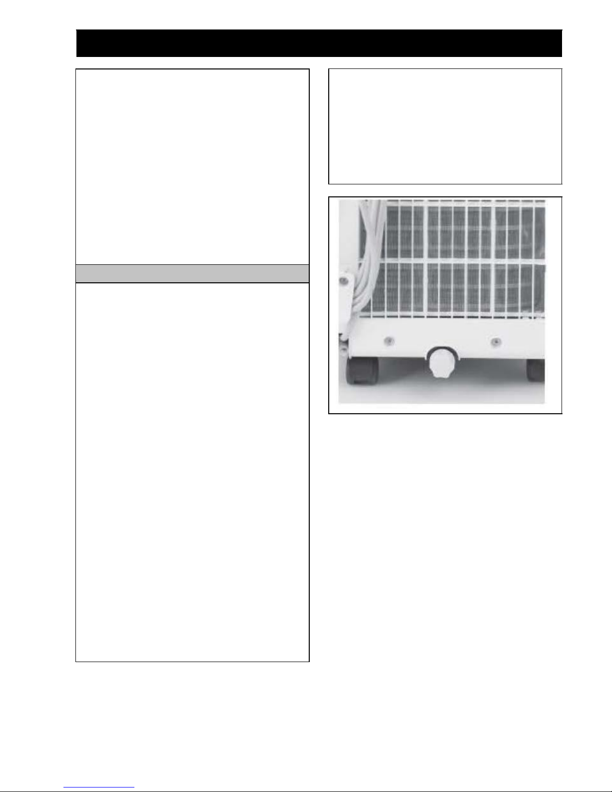
Manual drain
1.Ones the unit shuts down upon full water, turn off the
power of ttio unit and than unplug the power plug.
Note: move the unit carefully to avoid spillage of water
in the water tray at the bottom of the unit.
2.Put the vessel that holds water below the water outlet
at the back of the unit.
3.Screw off the drain cap, unplug the water plug and
water will flow into the vessel that holds water
automatically.
Note:
1. Protect the drain cap and water plug property.
2. Turn the unit slightly backward when draining.
3. If the vessel that holds water can nor hold all water
in the unit before the vessel that holds water it full
of water, block the water outlet with the water plug
possible to prevent the water from flowing onto the
around or carpet.
4. Once the water is fully drained, insert the water
plug and acraw on the water cap tightly.
Note: 1. Turn on the unit only after the water plug and
drain cap are installed property; otherwise, the
condensate of the unit will flow onto the ground or
carpet.
Note: frequent condensate tray full alarm may be a
problem.
Contact the service center for advise/ help/service.
Alternatively, in extreme humidity in tropical zones,
the unit may not be able to evaporate the condensing
water effectively, in this instance, follow the same
procedure for dehumidifying mode.
8
MAINTENANCE
Prior to maintenance and servicing of the unit, turn off the power and unplug the plug.
Surface cleaning
Clean the surface of the unit with wet soft cloth. Do not
use chemical solvents containing spirit such as
alcohol or gasoline, otherwise, the surface of the air
conditioner may be damaged and even the whole unit
may be damaged.
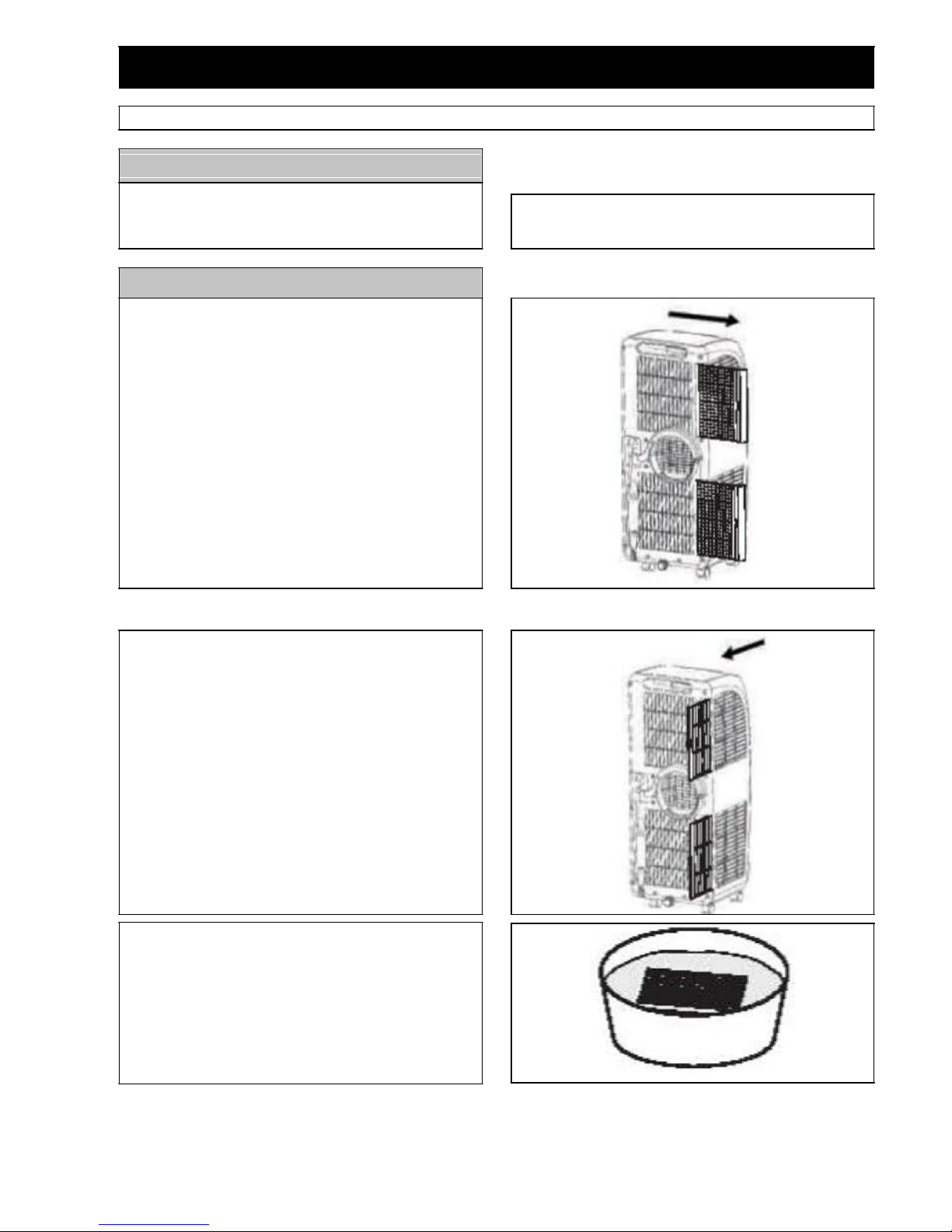
Cleaning of the filter frame and filter mesh
Clean the filter mesh once every two weeks. If the
filter frame and filter mesh are clogged with dust, the
function of the air conditioner may decrease.
1.Grip the gripping position of the evaporator filter
frame and the condenser filter frame and take out
the filter frame gently in the direction shown by the
arrow.
2. Grip the gripping position of the evaporator filter
frame and condenser filter mesh and take out the
filter mesh gently in the direction shown by the
arrow.
Note: when taking out the filter frame or filter mesh,
the force shall be applied evenly to avoid damage of
the filter frame or filter mesh. Be sure to take out the
filter frame first and then take out the filter mesh.
3. Fit the evaporator filter frame, condenser filter frame,
evaporator filter mesh, and condenser filter mesh into
warm water (about 40°) to which neutral cleaner is
added for cleaning and then dry them in the shade.
Note: Do not damage the mesh fabric onthe fitter frame
and filter mesh.
9
MAINTENANCE
Installation of the filter frame and filter mesh
Special note: Be sure to install the filter mesh first
and then install the filter frame.
1. To install the evaporator filter mesh and condenser
fitter mesh, point the back end of the filter mesh
toward the socket and then push the filter mesh
evenly and gently into the socket. Note: Install the
filter mesh in the reverse order of removal. The fitter
mesh must be installed Into place; otherwise, the filter
frame may not be installed into place. Install the filter
mesh gently so not to damage it.
2.To install the evaporator fitter frame and condenser
filter frame, point the back end of the filter frame
toward the socket and then push the filter frame
evenly and gently into the socket. Note: Install the
filter frame in the reverse order of removal. Before
installing the filter frame you must make sure that the
filter mesh is installed. Install the filter frame gently
so not to damage it.
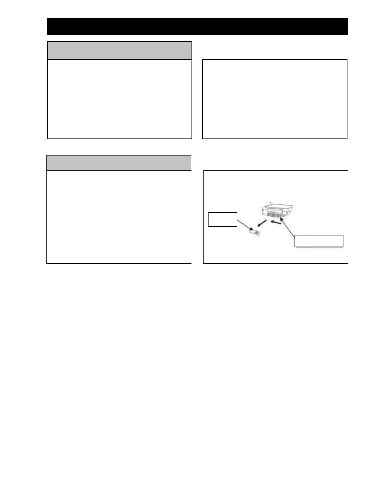
Cleaning of the handle and remote control
storage area
1. Take the remote control out of the remote control
storage area in the direction shown by the arrow.
2.Clean the handle position and remote control
storage areas of this unit with wet soft cloth.
Note: the wet soft doth must be wringed out. Do not
dip water into this unit.
3.If the remote control needs to be put back into the
remote control storage area, put it back into the
storage area in the reverse direction of removal.
Remote
control
Area for storing
remote control

10
END OF SEASON STORAGE
1. Screw off the drain cap, unplug the water plug and
drain the water in the water tray to another vessel
that holds water.
Note: the tilt angle ofthe unit shall not be greater than
30 degrees.
2.Start the unit, turn the mode to the low fan speed
state of the air supply mode, keep this for half a day
and dry the interior of the unit to prevent mold.
3.Turn off the unit, unplug the power plug, wrap the
power cord around the wire-winding post, insert the
plug into the universal jack at the back side of the
unit; install the water plug and drain cap.
4. Remove the heat exhaust hose assembly and keep it
properly.
Note: to remove the heat exhaust hose assembly,
hold the handle of the C shape buckle of the heat
exhaust hose by hand, pull the C shape buckle
outward evenly, rotate the C shape buckle of the heat
exhaust hose clockwise once the buckle is separated
from the snap position of the C shape buckle of the
back shell and then take out the heat exhaust hose
assembly.
5.Pack the air conditioner properly with soft plastic
bag, put the unit in a dry place & take appropriate
dust-proof measures, and keep the unit out of the
reach of children.
6.Take out the batteries of the remote control and keep
it properly.
Note: ensure that the unit is put in a dry place. All
accessories of me unit shall be protected properly.
TROUBLESHOOTING
Trouble
Solution
Unit does not operate
Is the unit plugged in?
Is the power outlet switched on?
Is the Full Water Indicator on? ((If so empty the condensed water).
Unit does not cool effectively
Is the room too large?
Is there direct sunlight onto the unit? (close curtains end pull down
blinds)
Are windows or doors open?
Is there another heat source in the room?
Is the filter dirty or contaminated?
Is the air intake blocked?
Is the outlet duct venting the hot air property?
Is the room temperature below your selected temperature?
Too Noisy
Is the unit positioned on an uneven hard floor surface creating
vibration?
Note: A soft carpeted surface may absorb vibrations.

11
FAILT CODES, REMEDIAL MEASURES
Code
Solution
Full water Indicator illuminates and beeps.
The water in the base plate of the unit reaches the fill I water level,
drain the water in the base plate refer to drainage section.
Е1
The refrigerant / thermostat / sensor has an anomalous reading, ensure
adequate ventilation around machine, wait 30 minutes and restart. If
fault code persists, this may be due to equipment malfunction, please
contact customer service.
Е2
The room thermostat / sensor has an anomalous reading, ensure
adequate ventilation around machine, wait 30 minutes and restart. If
fault code persists, this may be due to equipment malfunction, please
contact customer service.
Е3
The cooling system is not functioning at normal efficiency. The most
likely cause is an exhaust restriction, kink, or obstruction. Shutdown
and fully inspect appliance, inspect exhaust duct (refer to assembly
instructions). Otherwise, this may be due to equipment malfunction, or
refrigerant leakage, please contact customer service.
Е4
The condenser requires defrosting, the unit will stop working for a
several minutes to Auto-Defrost; then will resume operation as normal.
Important note: The unit complies with relevant safety and performance standards. An electrical specialist must
carry out repairs.

Produced byorder andunder the control ofthe License
Holder:SHIVAKI (Japan) IndustriesLtd., 2001, Central
Plaza, 18 Harbor road, Venchay, Hong Kong
WWW.SHIVAKI.COM
Mobilaus kondicionieriaus eksploatavim oinstrukcija
Modelis: SHPC-0915E
Šiluminė galia:
9000 BTU/val
.
.

TURINYS
IR EKSPLOATACIJAI.................................................................................... 1
PRIETAISO INFORMACIJA ......................................................................... 2
SURINKIMAS................................................................................................... 3
....................................................................................... 5
DISTANCINIO VALDYMO PULTAS ........................................................... 5
............................................................................................ 6
KONDENSATO NULEIDIMAS...................................................................... 7
TECHNINIS APTARNAVIMAS..................................................................... 8
TECHNINIS APTARNAVIMAS..................................................................... 9
SEZONINIS LAIKYMAS .............................................................................. 10
............................................................................. 10
............................. 11
.
1
IR EKSPLOATACIJAI
.
Jei prietai
.
doti
perstatymo metu.
Sumontavus
Prijei jis
aptarnavimo ir remonto metu
KGALIMAnaudotiTIKsu
saugikliu,kuriomaksimaligaliaatitinka
ki
.Elektros
maitinimo jungiklis ir lizdas
Teisingai
tinkamai utilizuotos.
prietaisas yra .
.
neatitinka .
Neleiskite
elektros
atstovas arba specialistas.
aerozolius)laikykiteesniu,kaip50
cm nuo prietaiso atstumu.

2
PRIETAISO INFORMACIJA
Nr.
Pavadinimas
1
Valdymo panelis
2
Ortakis
3
Distancinio valdymo pulto signalo imtuvas
4
Reguliuojamas ortakio deflektorius
5
Transportavimo rankena
6
Ratai
7
Nuleidimo anga
8
Tinklo laidas
9
Oro filtrai
10
11
Fiksatorius
Nr.
Pavadinimas
1
Adapteris su spragtukais lengvam oro
2
idimo vamzdis
3
Reguliuojamas komplektas montavimui
atvirame lange. Adapteris lankstaus oro
4
Apvalus adapteris
5
Apvalaus adapterio dangtis
Valdymo panelis
Ortakis
Distancinio
valdymo pulto
signalo imtuvas
Reguliuojamas
ortakio
deflektorius
Ratai
Transportavimo
rankena
Oro išleidimo
anga
Fiksatorius
Oro filtrai
Tinklo laidas
Nuleidimo anga
Adapteris su
spragtukais
Lankstus oro
išleidimo
vamzdis
Reguliuojamas komplektas
montavimui lange.
Apvalus
adapteri
s
Apvalaus
adapterio
dangtis
Skats no aizmugures

3
SURINKIMAS
montavimas
.
390 mm - 1500 mm
ribose,
rangyti
SVARBU:
ai, prietaisas gali
perkaisti ir atsijungti.
vienos p
4
MONTAVIMAS
Montavimas nuolatiniam naudojimui
Apvalus adapteris (4 poz.)
nereikia demontuoti, jeigu kondicionieriumi
.
Montavimai laikinam naudojimui:
arba pakeliamas langas
1.Atidarykite /
2. laikino naudojimo
.
atitinka angos .
3.
4.
apvaliame adapteryje.
5.
laikino naudojimo nkite.
6.
kreipi.
7.
naudojimui.
8.
Vientisa siena arba
langas
Apvalus adapteris
langui
Skečiamasis langas
Reguliuojamas
komplektas
montavimui lange
Apvalus adapteris
Oro išleidimo vamzdis
Pakeliamas langas
cm
Table of contents
Languages:
Other Shivaki Air Conditioner manuals


Popular Air Conditioner manuals by other brands
UC-K3DNA1A/I Service manual")


Fujitsu
Fujitsu AST20AGCW operating manual

Fujitsu
Fujitsu AR G45LMLA Series Design & technical manual

Beko
Beko BS 107 C user manual

Haier
Haier HSU-07RS03/R2, HSU-09RS03/R2, Operation manual

Samsung
Samsung AR KSFH Series manual

Mitsubishi Electric
Mitsubishi Electric CITY MULTI PKFY-P NLMU Series installation manual