Shivaki SSH-I076BE User manual

WALL MOUNTED SPLIT-TYPE AIR CONDITIONERS
CONTENTS
1. IMPORTANT NOTICE ···································2
2. OPERATION DETAILS·······································3
3. WIRING DIAGRAM ············· 11
4. EXPLOSION VIEW AND PARTS LIST·············12
Models
SSH-I076BE/SRH-I076BE
SSH-I096BE/SRH-I096BE
SSH-I126BE/SRH-I126BE
OB207t-1qxp 25/9/97 8:51 PM Page 1
SHIVAKI
SERVICE MANUAL No.TE150107

IMPORTANT NOTICE
This service manual is intended for use by individuals possessing adequate
backgrounds of electrical, electronic and mechanical experience. Any
attempt to repair the appliance may result in personal injury and property
damage. The manufacturer or seller cannot be responsible for the
interpretation of this information, nor can it assume any liability in
connection with its use.
The information, specifications and parameter are subject to change due to
technical modification or improvement without any prior notice. The
accurate specifications are presented on the nameplate label.
How to order spare parts
To have your order filled promptly and correctly, please furnish the
following information:
1. Model No. with Indoor or Outdoor
2. No. in the Explosion View
3. Part Name
4. The quantity you ordered
TCL Air Conditioner Service ManualTCL Air Conditioner Service ManualTCL Air Conditioner Service Manual
Air Conditioner Service Manual
2
3
Note: Each mode and relevant function will be further specified in following pages.
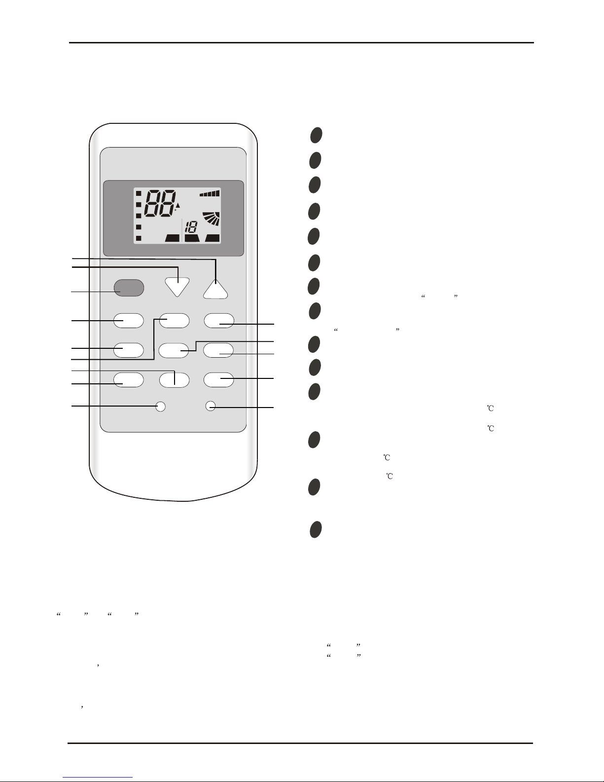
Remote controller
Air Conditioner Service Manual
Operation Details
Remote Control
The remote controller is not presetting as Cooling Only Air Conditioner or Heat Pump by manufacturer.
Each time after the remote controller replace batteries or is energized, the arrowhead will flashes on the front of
Heat or Cool on LCD of the remote controller.
User can preset the remote controller type depending on the air conditioner type you have purchased as
follows:
Press any button when the arrowhead flashes on the front of Cool , Cooling Only is set.
Press any button when the arrowhead flashes on the front of Heat , Heat Pump is set.
If you don t press any button within 10 seconds, the remote controller is preset as Heat Pump automatically.
Note :
If the air conditioner you purchased is a Cooling Only one, but you preset the remote controller as Heat Pump, it
doesn t bring any matter. But if the air conditioner you purchased is a Heat Pump one, and you preset the
remote controller as Cooling Only, then you CAN NOT preset the Heating operation with the remote controller.
1
2
4
3
5
6
7
8
MODE button
ECO button
ON/OFF button
FAN SPEED button
TEMP UP button
TIMER button
SLEEP button
TEMP DOWN button
To select the mode of operation.
In cooling mode,press this button ,the temperature
will increase 2 on the base of setting temperature:
In heating mode, press this button, the temperature
will decrease 2 on the base of setting temperature.
To switch the conditioner on and off.
To select the fan speed of auto/low/mid/high.
To set automatic switching-on/off.
Increase the temperature or time by 1 unit.
To activate the function SLEEP .
Decrease the temperature or time by 1 unit.
1
3
4
5
11
12
10
9
8
7
6
ON OFF ON
C
AUTOQUIET
POWERFUL
hr
DELAY
DRY
FAN
HEAT
TIMER
HEALTHY
AIR
SWING
FAN
SPEED
2
COOL
FEEL
ON/OFF
MODE TIMER
FAN SPEED SUPER ECO
ANTI-MILDEW
SWING SLEEP HEALTHY
DISPLAY RESET
13
14
9
SUPER button
In cooling mode, press this button, the unit will give
the maximum cooling temperature with 16
In heating mode, press this button, the unit will give
the maximum heating temperature with 31 .
9
SWING button
10
To activate or deactivate of the movement of the
DEFLECTORS .
12
DISPLAY button
To LED display (if present).
switch on/off the
13 HEALTHY button
To switch - on /off HEALTHY funtion.
It is a button
which controls the ionizer or plasma generator only
for inverter type.
9RESET button
14
To restart REMOTE CONTROL.
15
9
11
ANTI-MILDEW
To activate the functionANTI-MILDEW.

Air Conditioner Service Manual
Electronic controller
NOTES:
RT-------Room Temperature.
IPT------Indoor Pipe Temperature.
ST------indoor Setting Temperature.
OPT---Outdoor Pipe Temperature.
CRT---Compensated Room Temperature
1. Automatic mode
1) The initial RT determines A/C working mode and setting temperature (ST), the mode is
determined effective only once unless A/C shut-down then re-started. If from other modes
switches to automatic mode (including mode conversion after shutdown), it should be that the
compress stop more than 3 min then temperature judgment and automatic mode are conducted
(it can conduct immediately from fan mode switched to automatic, the indoor fan stops, three
minutes later the response is made and start up). Within 3 min, the output as: Showing the
room temperature, indoor fans starts (or anti-cold airflow), the outdoor fan stops;
2) With auto re-start controller, once being turned off or in case of an accidently power cut, the A/C is
able to retain and restore the original mode when being turned on or the power supply is resumed,
if the auto restart function activated. power-down after power-on; while if the auto restart
function isn’t activated, the A/C enters standby state.
Heat pump
Mode Initial RT Initial ST
Cooling RT≥26°C 23°C
Dry 26°C>RT≥20°C 7°C
Heating RT<20°C 23°C
Cooling-only
Mode Initial RT Initial ST
Cooling RT≥26°C 23°C
Dry 26°C>RT≥20°C 7°C
Ventilating RT<20°C -
Under automatic mode (including from automatic converted into Dry mode), when the temperature
UP or DOWN signals from the remote controller is received, the setting temperature ST
adjusts
correspondingly to the current room temperature plus or minus 1°C, the automatic regulating
temperature range is ± 2°C.
2.Cooling mode
1) The control of the compressor
a.
When RT-ST≥1°C,the compressor is running.
b.
When RT-ST<-1°C,the compressor is off.
c.
When -1°C≤RT-ST<1°C, the compressor keeps its original state.
2) Outdoor fan motor and the compressor run simultaneously (except for defrosting).
3) The control of indoor fan motor:
a.
Indoor fan motor can operate by automatic, low, middle, and high airflow speed circularly.
b.
Indoor fan motor automatic airflow speed control, it works as shown in Figure 1:
4

Air Conditioner Service Manual
Hi
Mid
Lo
RT-ST 1°C 2°C 4°C
Figure 1 Cooling automatic airflow
When the temperature change leads the fan speed variation, the switch can only be made orderly,
and every grade of air flow speed runs 1 minute at least.
2. Dry mode
While select to this mode, the air conditioner operates for 3 minutes according to cooling mode firstly
(ST set at 7°C), and then takes the detected backflow air temperature minus 2°C as a new set
temperature (the minimum value of 5°C) and runs according to cooling mode, indoor fan operates at
low-speed, at this moment the setting operation of Fan speed is invalid but Swing is adjustable.
4. Heating mode
On the Heating mode, the room temperature (RT) is compensated (CRT), a fter that, the room
temperature display on the LED is CRT=RT-3°C.
1) The control of the compressor
a.
When ST-CRT≥1°C,the compressor is running.
b.
When ST-CRT<-1°C,the compressor is off.
c.
When -1°C≤ST-CRT<1°C, the compressor keeps its original state
2) Outdoor fan motor and the compressor run simultaneously (except for defrosting)
3) The control of indoor fan motor:
a.
Indoor fan motor can operate by automatic, low, middle, and high airflow speed circularly.
b.
Indoor fan motor automatic airflow speed control, it works as shown in Figure 2:
Figure 2 Heat automatic airflow
When the temperature change leads the fan speed variation, the switch can only be made orderly,
and every grade of air flow speed runs 1 minute at least.
4) Vane motor control: run as set state.
5) 4-way valve control:
a.
Under heating mode, the four-way valve maintains well-connected status (including the
compressor stops on set condition, but except for the defrosting process)
b.
When the mode switches into the heating mode or A/C start-up, four-way valves will open 5
Seconds before the compressor starts; while the mode exits from the heating mode or A/C turn off,
the four-way valve will close 2min later after shut-down the compressor.
6) Defrosting function:
During defrosting, once mode change, economic operation or temperature setting signals received,
the buzzer and display will make response immediately, but the other operations won’t implement
until defrosting finished;
Hi
Mid
Lo
ST-CRT 1°C 2°C 4°C
5
Air Conditioner Service Manual
6
During defrosting, the signals of on-off, timing, sleep, fan speed and swing will be responded, but the
fan speed and swing should be in accordance with Cold Air Prevention rules.
Except the above signal processing during defrosting, no other signals will be dealt with, but only a
voice buzz.
During defrosting, electrical heating (optional function) stops compulsively.
Defrosting Enter and Exit program:
Option 1:with jumper JC
The condition of enter defrosting: run into defrosting once any of condition 1, 2, and 3 met.
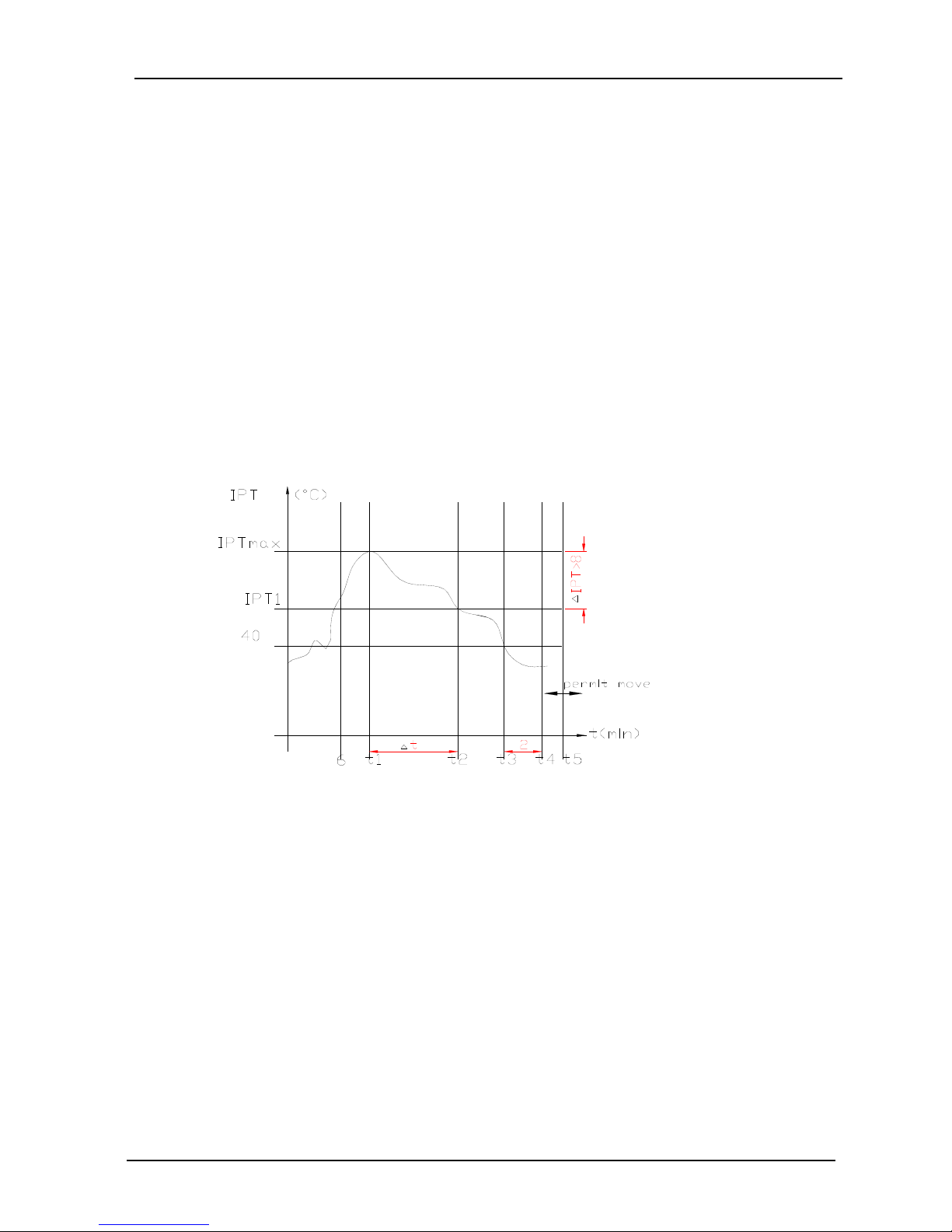
Condition 1:As shown in figure 3
Definition:
The followings are all required to meet:
a.
IPT1 settles for IPT1=IPTmax-△IPT
b.
t5≥50min(running time t5≥50min(the compressor runs cumulatively), t5 is removable, and could
be less than t1)
c.
IPT<40°C,and lasts 2min。
Running into defrosting on condition 1, the first running time of set defrosting is F (8min); after running
a defrosting cycle, the defrosting time should be determined and adjusted.
Figure 3
Condition 2: When running time is more than or equal to 120 min (compressor is running
accumulatively), the indoor temperature is less than 35°C for 2 min sustained. Running into
defrosting under condition 2, defrosting time set is 8 min.
Condition 3: after the compressor is operating for 20min continuously, the indoor pipe temperature is
less than 23°C (cold air prevention wind temperature) when the fan stops running (including
temperature dropping when compressor operating, not including the compressor’s starting up
course), and the machine runs into defrosting according to any one condition as below.
Running into defrosting under condition 3, defrosting time set is 10 min.
a) Running into the first defrosting in 20 min after start-up.
b) The interval from last defrosting equivalent to or more than 50 min (stopping the compressor or the
machine in standby is allowed in the meantime).
Option 2: Without Jumper JC, and no OPT outdoor sensor
when the compressor runs for 45 min (accumulated), if the indoor coil temperature is less than 40°C
for 2 min, the machine runs into defrosting, and lasts for 3min, otherwise when the compressor

Air Conditioner Service Manual
runs for 120 min (accumulated), the machine runs into defrosting automatically and last for 10 min.
Option 3: Without jumper JC, but with OPT outdoor sensor
While heating, when the temperature of condenser is lower than E °C (-4°C), and the compressor
runs for 45 min (accumulated), then the machine runs into defrosting and lasts for 10 min.
Option 4. On heating, while the outdoor fan motor stopped but the compressor operated
accumulative totally 30min, then the machine runs into defrosting and last for 8 min. if the
accumulative totally less than 30min, but accord with one of the condition option 1-3 then the
machine runs into defrosting at the option 1-3 and the accumulative total time restarts from 0.
Conditions for quitting defrosting
(1) The quitting conditions for option 1, option 2 and 4, the machine quits from defrosting if any
one below condition met.
a.
Defrosting time is over.
b.
When it runs in defrosting for three minutes, the IPT indoor coil temperature rises 15°C or above
from the bottom point.
(2) The quitting conditions for option 3.
When OPT ≥20°C or defrosting for more than 10 min, then quit from defrosting.
(3) Defrosting process shown in Figure 4
Figure 4 Defrosting process
7) Auxiliary electric heating function (optional)
(1) The default condition is automatic on/off the electric heating function.
(2) The conditions of auxiliary electric heating works (all the following conditions must be met)
a.
the compressor runs for more than 3min;
b.
indoor fan runs normally;
c.
not in defrosting state;
d.
auxiliary electric heating is turned off for more than 30s。
e.
ST-RT≥0°C;
f.
RT﹤25°C;
g.
IPT≤43°C;
(3) The conditions of stopping auxiliary electric heating(any one of the following conditions
met, the state stops)
Compressor Relay
ON
OFF ON
ON
OFF
OFF
ON
ON
ON
OFF
39S 19S 5S
t
4-way Valve
Outdoor Fan
The indoor fan runs in anti-cold wind modle
Defrosting time MAX 12 Min
ON
7

Air Conditioner Service Manual
a.
the compressor stops
b.
RT≥27°C;
c.
IPT≥50°C
d.
indoor fan stops。
e.
running into sleeping function
5. Fan mode
1) Indoor fan motor is running at setting speed (the speed is same as that of heating).
2) Vane motor control: running according to the setting condition.
3) The outdoor unit doesn’t work under fan mode.
6. Sleeping mode
1) Under sleep mode, the indoor fan motor is running at a low speed, except that the power light
and sleep light are on, timer light is on/off according to the setting state, running light is off. LED will
be off after displaying 30S.
2) Temperature control:
(1) From Cool mode to Sleep mode, one hour later, the operates Temp.=ST+1°C,another one
hour later, the operates Temp.=ST+2°C,after then unchanged.
(2) From Heating mode to Sleep mode, one hour later, the operates Temp.= ST-1°C,another one
hour later, the operates Temp.=ST-2°C,after then unchanged.
3) the machine will automatically shut up after running 10 hours under sleep mode.
Timer on start-up and sleep mode are implemented at the same time, and the sleep mode can not be
functioned.
7. Timing function
The timing scale is between 10min to 24h, when the time fixed is less than “10” hours, the displayed
time is shown by 0.5 hour as the unit, when the time fixed is more than or equal to “10” hours, the
displayed time is shown by 1 hour as the unit.
8. Emergency switch(ON/OFF).
1) When stand-by, to operate by pressing the emergency switch as follows:
To Press the emergency switch in three seconds, the buzzer rings once, and to release, the machine
runs into cooling mode; if to holding on, the buzzer rings twice, then the machine runs into heating
mode, while when the machine is on, to press the Emergency switch, the buzzer rings once and then
the machine shut down.
2) The machine is running mandatorily as the selected mode within 30min after emergency operation,
indoor fan motor running in high-speed, and stepping vane swinging. The machine runs into
automatic mode 30min later, the selected mode unchanged, the set temperature to be 23°C, the
rotate speed of indoor fan motor is automatic, and stepping vane swinging also.
3) To press the emergency button when the machine operating, then the machine runs into stand-by.
4) Under emergency operation, the function of Compressor’s time-delay protection, anti-frosting
protection in cooling mode, Overheating protection in heating mode, sensor fault protection and
defrost operate are effective.
5) Under emergency operation, once effective signal from remote controller is received, then the
A/C exits form the emergency mode, and operate according to the setting value from remote controller.
9. Auto-restart function
1) The PCB retains the setting parameters in case of power off. When the power supply is resumed,
the machine, which has been started up the power-off memory function, is able to restore into the
original running state automatically.
2) To press the emergency button and power on the unit, and hold on for10 seconds, The buzzer
8

will ring
3) To cl
four time
10. Prot
1) Com
a.The P
along 3
function
B.The
(except
c.After
2) Anti-f
If IPT≤
motor r
compre
3) Overh
If IPT≥
motor ru
indoor f
4) Cold
a.
Whe
up cond
stoppin
within 2
Under h
operatio
within 1
b.
When
auxiliary
location
goes on
T t ii
three time
ose auto res
es.
tection/Tro
pressor’s pro
PCB which
3min delay
n, even whe
compressor
for
defrostin
the compres
frosting prote
≤0°C detecte
uns at high
essor activ
heating prot
≥55°C, the
uns at
high-
an motor re
air preventio
en running
ditions, the
gthe indoor
min, then o
heating proce
on (includin
min, 1min l
nthe indoo
yelectric h
and turn b
nto run at lo
Temperature rising
s, after this
start function
ubleshootin
otection:
has Auto-re
protection
en the PCB
r’s 3 min inte
ng process)
ssor started,
ection of in
ed in consec
h-speed forc
vated, indoo
tection (hea
outdoor fa
-speed forci
estores the o
on (heating
into the he
fan speed
rfan motor),
operating by
ess, while th
gstopping
aterthe fan
or fan moto
eating wor
back to norm
ow-speed ac
Set sp
Stop the
25°C
34°C
Air C
operation,
nwhile it is
ng.
estart functi
when pow
is power-o
erval protec
.
,the compr
door evapor
cutive 3 mi
cibly; if IP
rfan motor r
ting mode):
nmotor sto
bly. When I
original stat
mode):
eating mod
is regulat
2 min later
Figure 5.
he compress
the indoor
will be sto
rrunning
ks, the va
mal vane an
cordingly, t
Figure
eed
fan
C
C
Conditioner Se
the auto rest
activated, re
on, once thi
er on. If th
n, the comp
tion: the com
essor’s state
ator(cooling
n, compress
T≥5°C detect
restores the
ps; if IPT≥6
PT≤48°C,ou
e.
e, once the
ed accordin
the indoor f
sor stop (inc
fan motor) i
pped forcibly
at a low-spe
ne immedi
gle. While
he vane turn
e5 Cold air p
ervice Manual
tart function
epeat proces
s function is
he PCB h
pressordo
mpressorc
eisn’t subje
mode):
sor and outdoor
ted 3min la
original sta
65°C, the c
utdoorfan
ecompress
gto the co
an motor st
cluding stop
is regulated
y.
eed under
ately withdr
auxiliary ele
s to cold ai
prevention
Stop the fa
27°
C
23°C
Set speed
Set speed
is activated
ss as above
started u
asn’t been
esn’t proces
an’t start-up
cted to the
fan motor
ter, then o
te.
ompressor
motorand th
or fails to
il temperat
ops. If the c
ping forprot
according
cold air pre
aws from t
ctric heating
rprevention
n
.
2), the buzz
p, the comp
started up
s3 min del
until it stop
changes on
stopped
utdoorfan m
stops, a n d
ecompresso
comply wit
ure in 2 mi
ompressor s
ection), the f
to the coil
vention ope
he cold air
stops, indo
location.
Temperature dropping
zer will ring
ressorgoes
Auto-restar
lay function
s3 min late
ST,RT in 3
, indoorfan
motor and
indoor fan
or power on
h the start-
in (includin
starts up
fan motor
temperature
ration, once
rprevention
or fan moto
s
rt
.
r.
min.
,
-
g
e
e
n
r
9

Air Conditioner Service Manual
2) The following table shows the fault protections. When failures happens, the PCB alarms and
buzzer rings three times. Failure code appears, and the PCB operates protection procedures.
Failure code: For the machine with LED display, the code shows on LED, for machine without LED,
the code reflects by the running light.
Failure Running Light Flash LED Display
RT Sensor Failure Once / Period E1
IPT Sensor Failure Twice / Period E2
Indoor Fan Motor Failure 6 times / Period E6
When failure happened, the code is displayed statically, if there are several failure codes should be
reported at the same time, then failure codes appears one by one every eight seconds
correspondingly.
a.
Sensor’s failure protection: when the sensor’s temperature is out of the range -50°C≤T≤110°C,
then sensor failure is determined. Once RT, IPT sensor failures appear, the compressor stops and
indoor and outdoor fan motors shut off. Remote controller doesn’t response to any signal except for
shutdown. During failure the machine can run in fan mode. After the failure is settled, the PCB
restores to standby status.
b.
Failure protection of Indoor PG fan motor: If there is no feedback signal of rotate speed within 5s,
the indoor fan motor stops, meanwhile, the compressor, outdoor fan motor, four-way valve and
auxiliary electric heater etc. cut down. 10 seconds later, the indoor fan motor restarts again, once
there is no feedback signal of rotate speed within 5 seconds either, then the machine stops and
goes into indoor fan motor failure protection, buzzer rings three times, and running light flashes at 6
times per 8 seconds. When the failure is confirmed, once there is feedback signal, the failure is
relieved automatic.
10

Air Conditioner Service Manual
11
WIRING DIAGRAM
MODEL: SSH-I076BE/SRH-I076BE, SSH-I096BE/SRH-I096BE, SSH-I126BE/SRH-I126BE
INDOOR UNIT:
OUTDOOR UNIT

Air Conditioner Service Manual
12
EXPLOSION VIEW
Mode: SSH-I076BE, SSH-I096BE, SSH-I126BE
INDOOR UNIT:
15
6
14
11
13 12
8
10
9
7
1
5432
19
18
17
16
23
24
21
20
22
26
25
No. Part No. Part Name Q’ty Remark
1 1080030003 Installation Plate 1
2 1080320807AC Base 1
3 1070020017AA Cross Fan 1
4 1070100010 Bearing Mount 1
5 211205977A Evaporator 1
6 1070251833AP Water Drainage Assembly 1
7 1070321035 Vertical Vane Assembly 2
8 1070251372AE Face Frame 1
9 1070321022AC Screw Cover 2
10 1070250106 Air Filter 2
11 1070252211 Display PCB Box 1
12 1090321196 Display PCB 1
13 210705001 Front Panel 1
14 1170120044 Power Supply Cord 1
15 1070251837AE Vane 1
16 1070110011 Drainage Hose 1
17 1070040004 Cable Clamp 1
18 210900789 Main PCB 1
19 1070320113 Electrical Box 1
20 1170020011 Vane Motor 1
21 1073010501 Sensor Holder 1
22 1170030047 Indoor Motor 1
23 1070320111 Indoor Motor Cover 1
24 1170240001 Transformer 1
25 1170230001 Indoor Sensor Assembly 1
26 1080320818AB In And Out Pipe Fixer 1
27 1090050298BU Remote Controller 1
28 1070060003 Remote Controller Supporter 1
29 1190060827ABQ Indoor Carton 1
30 211310246 Left Foaming 1
31 211310247 Right Foaming 1
Not shown in Explosion view
Indoor Unit- SSH-I076BE
Air Conditioner Service Manual
13

No. Part No. Part Name Q’ty Remark
1 1080030003 Installation Plate 1
2 1080320807AC Base 1
3 1070020017AA Cross Fan 1
4 1070100010 Bearing Mount 1
5 211205977A Evaporator 1
6 1070251833AP Water Drainage Assembly 1
7 1070321035 Vertical Vane Assembly 2
8 1070251372AE Face Frame 1
9 1070321022AC Screw Cover 2
10 1070250106 Air Filter 2
11 1070252211 Display PCB Box 1
12 1090321196 Display PCB 1
13 210705001 Front Panel 1
14 1170120044 Power Supply Cord 1
15 1070251837AE Vane 1
16 1070110011 Drainage Hose 1
17 1070040004 Cable Clamp 1
18 210900789 Main PCB 1
19 1070320113 Electrical Box 1
20 1170020011 Vane Motor 1
21 1073010501 Sensor Holder 1
22 1170030047 Indoor Motor 1
23 1070320111 Indoor Motor Cover 1
24 1170240001 Transformer 1
25 1170230001 Indoor Sensor Assembly 1
26 1080320818AB In And Out Pipe Fixer 1
27 1090050298BU Remote Controller 1
28 1070060003 Remote Controller Supporter 1
29 1190060827ABS Indoor Carton 1
30 211310246 Left Foaming 1
31 211310247 Right Foaming 1
Not shown in Explosion view
Indoor Unit- SSH-I096BE
Air Conditioner Service Manual
14

No. Part No. Part Name Q’ty Remark
1 1080030008 Installation Plate 1
2 1080320806AC Base 1
3 1070020026AA Cross Fan 1
4 1070100010 Bearing Mount 1
5 1110050067 Evaporator 1
6 1070321076AC Water Drainage Assembly 1
7 1070321035 Vertical Vane Assembly 2
8 1070321678AE Face Frame 1
9 1070321022AC Screw Cover 2
10 1070320109 Air Filter 2
11 1070252211 Display PCB Box 1
12 1090321196 Display PCB 1
13 210705002 Front Panel 1
14 1170120045 Power Supply Cord 1
15 1070321034AE Vane 1
16 1070110011 Drainage Hose 1
17 1070040004 Cable Clamp 1
18 210900585 Main PCB 1
19 1070320113 Electrical Box 1
20 1170020011 Vane Motor 1
21 1073010501 Sensor Holder 1
22 1170030047 Indoor Motor 1
23 1070320111 Indoor Motor Cover 1
24 1170240001 Transformer 1
25 1170230001 Indoor Sensor Assembly 1
26 1080320818AB In And Out Pipe Fixer 1
27 1090050298BU Remote Controller 1
28 1070060003 Remote Controller Supporter 1
29 1190060828BHX Indoor Carton 1
30 211310246 Left Foaming 1
31 211310247 Right Foaming 1
Air Conditioner Service Manual
15
Not shown in Explosion view
Indoor Unit- SSH-I126BE

Air Conditioner Service Manual
16
EXPLOSION VIEW
MODEL: SRH-I076BE, SRH-I096BE,SRH-I126BE
OUTDOOR UNIT:
10 11 12
8
9
765
17
13 14 16
15
19
18
20
21
23
22
24
432
25
26
27
1
No. Part No. Part Name Q’ty Remark
1 1071990038 Grille 1 Optional
2 1081990014 Top Cover 1
3 211200850AA Condenser 1
4 1081990018 Outdoor Motor Supporter 1
5 1170040062 Outdoor Motor 1
6 1070030006A Propeller Fan 1
7 1081990011 Left Grille Supporter 1
8 1081990016 Front Plate 1
9 1071990044 Fan Guard 1
10 211206798 Compressor And It Accessories 1
11 1120110016 4-way Valve 1
12 211206812 4-way Valve Assembly 1
13 210800528 Base 1
14 1081990012 Right Plate 1
15 1120120025 Two-way Valve 1
16 1081990013 Valve Supporter 1
17 1120130039 Three-way Valve 1
18 1073521301 Electrical Box Cover 1
19 1070040001 Cable Clamp(φ6) 1
20 1070040002 Cable Clamp(φ7) 1
21 1170500131 Terminal 1
22 1170100031 Fan Motor Capacitor 1
23 1170100014 Compressor Capacitor 1
24 1080010002 Capacitor Strip 1
25 1081990010 Electrical Parts Box 1
26 211206830 Capillary Assembly 1
27 1081990019 Partition plate 1
28 211313638 Base Carton 1
29 211313639GC Cabinet Carton 1
30 211313637 Base Foaming 1
31 211313636 Cover Forming 1
Air Conditioner Service Manual
Outdoor Unit- SRH-I076BE
Not shown in the Explosion view.
17

No. Part No. Part Name Q’ty Remark
1 1071990038 Grille 1 Optional
2 1081990014 Top Cover 1
3 211201000 Condenser 1
4 1081990018 Outdoor Motor Supporter 1
5 1170040062 Outdoor Motor 1
6 1070030006A Propeller Fan 1
7 1081990011 Left Grille Supporter 1
8 1081990016 Front Plate 1
9 1071990044 Fan Guard 1
10 211201021 Compressor And It Accessories 1
11 1120110016 4-way Valve 1
12 211206398 4-way Valve Assembly 1
13 210800528 Base 1
14 1081990012 Right Plate 1
15 1120120025 Two-way Valve 1
16 1081990013 Valve Supporter 1
17 1120130039 Three-way Valve 1
18 1073521301 Electrical Box Cover 1
19 1070040001 Cable Clamp(φ6) 1
20 1070040002 Cable Clamp(φ7) 1
21 1170500131 Terminal 1
22 1170100031 Fan Motor Capacitor 1
23 1170100014 Compressor Capacitor 1
24 1080010002 Capacitor Strip 1
25 1081990010 Electrical Parts Box 1
26 211206477 Capillary Assembly 1
27 1081990019 Partition plate 1
28 211313638 Base Carton 1
29 211313639GD Cabinet Carton 1
30 211313637 Base Foaming 1
31 211313636 Cover Forming 1
Air Conditioner Service Manual
Outdoor Unit- SRH-I096BE
Not shown in the Explosion view.
18

No. Part No. Part Name Q’ty Remark
1 1071990039 Grille 1 Optional
2 1080320105 Top Cover 1
3 211200353 Condenser 1
4 1080050004 Outdoor Motor Supporter 1
5 1170040058 Outdoor Motor 1
6 1070030051AA Propeller Fan 1
7 1080050001 Left Grille Suppoeter 1
8 1080320113 Front Plate 1
9 1080320112 Fan Guard 1
10 1100160012 Compressor And It Accessories 1
11 1120110016 4-way Valve 1
12 1120351191 4-way Valve Assembly 1
13 210800476 Base 1
14 1080050002 Right Plate 1
15 1120120021 Two-way Valve 1
16 1080050003 Valve Supporter 1
17 1121990040 Three-way Valve 1
18 1070350971 Electrical Box Cover 1
19 1070040001 Cable Clamp(φ6) 1
20 1070040002 Cable Clamp(φ7) 1
21 1170500131 Terminal 1
22 1170100010 Fan Motor Capacitor 1
23 1170100004 Compressor Capacitor 1
24 1080010006 Capacitor Strip 1
25 1081990010 Electrical Parts Box 1
26 1120351190 Capillary Assembly 1
27 1081990314 Partition plate 1
28 211311435 Base Carton 1
29 211311098FE Cabinet Carton 1
30 211311099 Base Foaming 1
31 211311100 Cover Forming 1
Air Conditioner Service Manual
Outdoor Unit- SRH-I126BE
19
Not shown in the Explosion view.
This manual suits for next models
5
Other Shivaki Air Conditioner manuals


