Shivaki SSH-PM074DC User manual

MULTI-SPLIT TYPE AIR CONDITONER
SERVICE MANUAL
V:4.0
●INDOOR UNIT:
AMS-07UR4SNVG4
(
VT
、
VL
、
VQ
、
UP
、
UL
、
UQ
、
NS
、
ZC
、
ZA
)
4
AMS-09UR4SNVG4
(
VT
、
VL
、
VQ
、
UP
、
UL
、
UQ
、
NS
、
ZC
、
ZA
)
4
AMS-12UR4SNVG4
(
VT
、
VL
、
VQ
、
UP
、
UL
、
UQ
、
NS
、
ZC
、
ZA
)
4
AMS-18UR4SVUP3
(
VG3
、
VL3
、
VT3
、
UP3
、
UL3
、
UQ3
)
AMD-09UX4SJD
AMD-12UX4SJD
AMD-18UX4SJD
AMC-12UX4SAA
AMC-18UX4SAA
●OUTDOOR UNIT:
AMW2-16U4SGC1
AMW2-20U4SNC1
AMW3-20U4SZD
AMW3-24U4SZD
AMW3-24U4SKC
AMW4-28U4SKC
AMW4-36U4SAC
HisenseCorporation

Table of contents
Page
1.OPERATING RANGE 1
2.SPECIFICATION 2
2-1 Unit specifications 2
2-2 Major component specifications 7
2-3 Other component specifications 9
3.OUTLINES AND DIMENSIONS 10
3-1 INDOOR 10
3-2 OUTDOOR 14
4.REFRIGERANT FLOW DIAGRAM 17
4-1 Refrigerant flow diagram 17
4-2 Evacuation procedures 20
4-3 Evacuation direction 21
5.ELECTRICAL DATA 22
5-1 Electric wiring diagrams 22
5-2 Electric control 33
5-3 Sensor parameter 40
6.CONTROL MODE 48
6-1 Indoor control mode 48
6-2 Outdoor control mode 51
7.TROUBLESHOOTING 54
7-1 Error codes 54
8.CHECKING COMPONENTS 56
8-1 Check refrigerant system 56
8-2 Check parts unit 58
9.PARTS LIST 58
9-1 Indoor 64
9-2 Outdoor 76

1
1.
.O
OP
PE
ER
RA
AT
TI
IN
NG
G
R
RA
AN
NG
GE
E
1
Temperature Indoor Air Intake Temp. Outdoor Air Intake Temp
Maximum 32℃D.B./23℃W.B. 43 ℃D.B./26℃W.B.
COOLING Minimum 21℃D.B./15℃W.B. 21 ℃D.B./15℃W.B.
Maximum 27℃D.B./18℃W.B. 24℃D.B./18℃W.B.
HEATING Minimum 20℃D.B/≤15℃W.B -7℃D.B./-8℃W.B.
2
2.
.S
SP
PE
EC
CI
IF
FI
IC
CA
AT
TI
IO
ON
NS
S
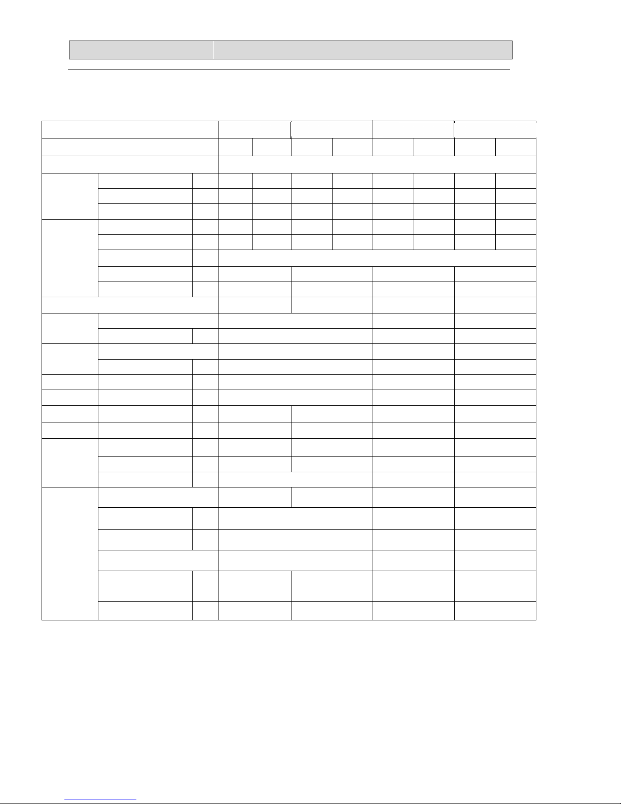
2
2-1. Unit specifications
2-1-1.OUTDOOR UNIT
Model AMW4-28U4SK
C
AMW3-24U4SKC AMW2-20U4SNC1 AMW2-16U4SGC1
Function CoolingHeating Cooling Heating Cooling Heating Cooling Heating
Power supply a.c 220V~240V/50Hz
Capacity kW 8.2 9.0 7.0 8.0 5.8 6.4 4.6 5.3
Dehumidification l /h ---- ---- ---- ---- ---- ---- ---- ----
Capacity Air flow m3/h ---- ---- ---- ---- ---- ---- 2400 2400
Rated current A 10.7 11.1 9.7 10.1 7.7 8.0 6.1 5.7
Rated input kW 2.4 2.49 2.18 2.21 1.7 1.75 1.4 1.3
Auxiliary heater A ------
Power factor % 99.9%99.9%99.9%99.9%
Electrical dat
a
Max. current A 15.0 15.0 14.5 10.0
EER/CPOP 3.42/.362 3.21/3.62 3.41/3.66 3.29/4.08
Model ATL165SD-C9AU DA130S1C-20FZ DA130S1C-20FZ
Compressor
Winding resistance
Ω0.590
(at75
℃)
0.95(20
℃
)0.95(20
℃
)
Model YDK70-6H-3 YDK55-6I-8 YDK29-6I-22Outdoor
fan motor
Winding resistance (at20
℃
)
Ω M:78;A:80 M:185;A:200 M:283.5;A:180
Net size L×W×H cm 109×41×84 98×35×64 80×26×57
Package size L×W×H cm 112×46×98 108×42×72 94×36×64
Net weight kg 67 66 46.5 36.5
Gross weight kg 77 76 52.5 40
Liquid pipe mm 6.35×4 6.35×3 6.35×2 6.35×2
Gas pipe mm 9.52×4 9.52×3 9.52×2 9.52×2
Refrigerant
piping Connection method Flare Flare Flare
Air direction ---- ---- ---- ----
Sound level (Hi) dB 57 57 48
Fan speed (Hi) rpm 840 840 900
Fan speed regulator 3 3 3
Refrigerant filling
capacity(R410a) kg 2.4 2.1 1.4 1.27
Special
remarks
Throttle mode EEV EEV EEV EEV
2
2.
.S
SP
PE
EC
CI
IF
FI
IC
CA
AT
TI
IO
ON
NS
S
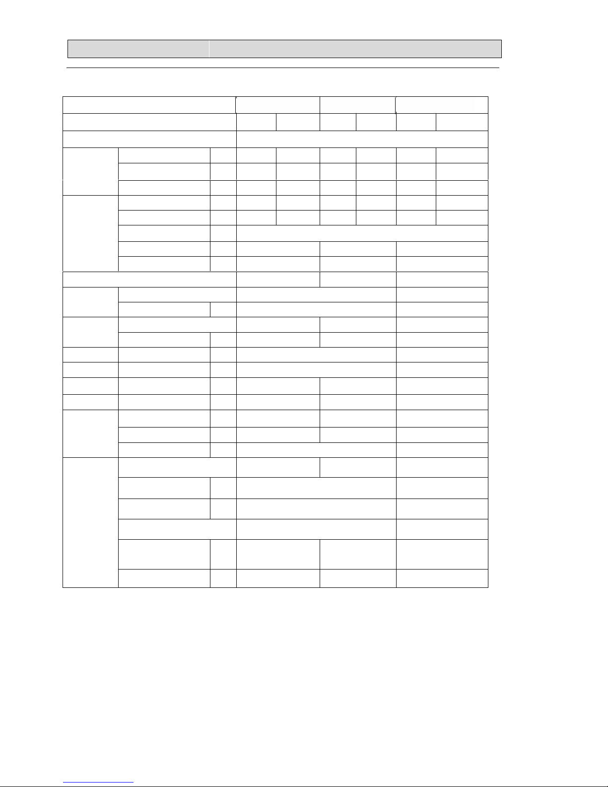
3
NOTE :Test conditions:
Cooling : Indoor: DB27℃/ WB19℃Outdoor: DB35℃/ WB24℃
Heating: Indoor: DB20℃/ WB15℃Outdoor: DB7℃/ WB 6℃
Model AMW3-20U4SZD AMW3-24U4SZD AMW4-36U4SAC
Function Cooling Heating Cooling Heating Coolng Heating
Power supply a.c 220V~240V/50Hz
Capacity kW 6.0 7.0 7 7.8 10 1.1
Dehumidification l /h ---- ---- ---- ---- ---- ----
Capacity Air flow m3/h ---- ---- 3200 3200
4200 4200
Rated current A 8.55 8.58 10.0 9.5 14.5 14.0
Rated input kW 1.87 1.9 2.18 2.1 3.1 3.04
Auxiliary heater A ------
Power factor % 99.9%99.9%99.9%
Electrical dat
a
Max. current A 13.5 15.5 22.0
EER/COP 3.21/3.70 3.21/3.71 3.22/3.62
Model ATL165SD-C9AU ATL232SJNC9AU
Compressor
Winding resistance
Ω0.590
(at75
℃)
0.95(20
℃
)
Model YDK55-6I-8
YDK70-6H-3 YDK95-6-9043
Outdoor
fan motor
Winding resistance (at20
℃
)
Ω M:185;A:200 M:78;A:80 M:59.1;A:85.8
Net size L×W×H cm 98×35×64 109×41×84
Package size L×W×H cm 108×42×72 111×46×98
Net weight kg 52 53 67
Gross weight kg 56 57 77
Liquid pipe mm 6.35×3 6.35×3 6.35×4
Gas pipe mm 9.52×3 9.52×3 9.52×4
Refrigerant
piping Connection method Flare Flare
Air direction ---- ---- ----
Sound level (Hi) dB 5357
Fan speed (Hi) rpm 840 800
Fan speed regulator 3 3
Refrigerant filling
capacity(R410a) kg 1.6 1.75 2.6
Special
remarks
Throttle mode EEV EEV EEV

2
2.
.S
SP
PE
EC
CI
IF
FI
IC
CA
AT
TI
IO
ON
NS
S
4
2-1-2.INDOOR UNIT
Model
AMS-07UR4SNVG4
AMS-09UR4SNVG
(VT4、VL4、VQ4、
UP4、UL4、UQ4、NS4
、
ZC4、ZA4)
AMS-12UR4SNVG4
(VT4、VL4、VQ4、
UP4、UL4、UQ4、
NS4、ZC4、ZA4)
AMS-18UR4SVVG
3
(VL3/VT3/UP3/
UL3/UQ3)
Function Cooling Heating Cooling Heating Cooling Heating
Power supply a.c 220V~240V/50Hz
Capacity kW
2.1/2.6
2.5/3.0 3.2 3.7 5.0 5.5
Dehumidification l /h 0.8 ---- 0.8 ---- 1.5 ----
Capacity Air flow m3/h 400 520 450 560 800 900
Running current A 0.2 0.2 0.2 0.20.4 0.4
Rated input kW 0.04 0.04 0.04 0.04 0.085 0.085
Auxiliary heater A ----
Power factor % ----
Electrical dat
a
Starting current A ----
EER/COP ----
Model ----
Compressor Winding resistance (at25℃
)
Ω----
Model YYW16-4-532 RPG25A-6
Indoor
fan motor Winding resistance (at20℃
)
ΩM:364;A:400.5; M:211.2;A:211;
Model ----
Outdoor
fan motor Winding resistance (at2
0
℃) Ω----
Net size L×W×H cm 75×25×19 75×25×19 92×31.3×22.6
Package size L×W×H cm
80×31×25(VQ:88
×33×26)
80×31×25(VQ:88×
33×26)100.7×38×29.7
Net weight kg 7.5 7.5 11.5
Gross weight kg 9.0 9.0 14.0
Liquid pipe mm 6.35 6.35 6.35
Gas pipe mm 9.52 9.52 9.52
Refrigerant
piping Connection method ----
Air direction 6 6 6
Sound level (Hi) dB 24/27 30 32
Fan speed (Hi) rpm 1150 1250 1300
Fan speed regulator 3 3 3
Refrigerant filling
capacity(R410a) kg ----
Special
remarks
Throttle mode ----
2
2.
.S
SP
PE
EC
CI
IF
FI
IC
CA
AT
TI
IO
ON
NS
S
7
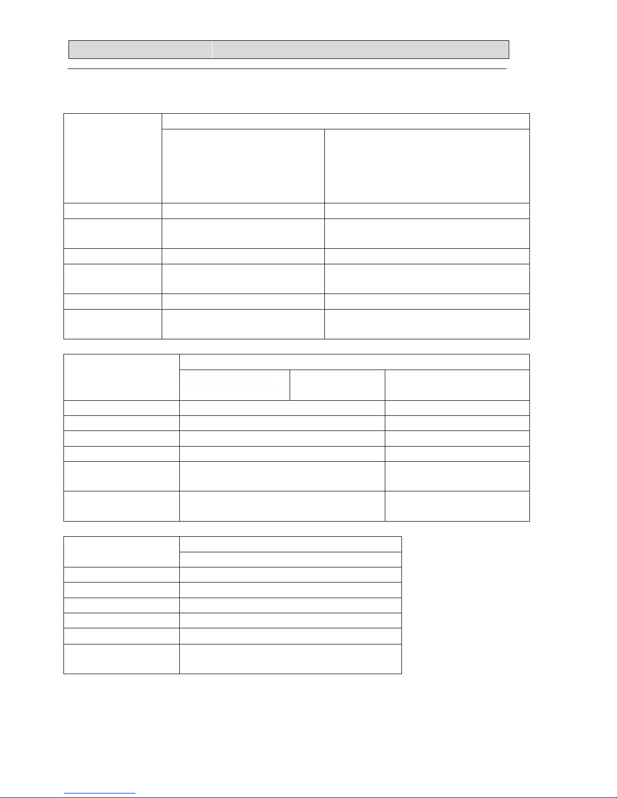
2-2. Major component specifications
2-2-1.INDOOR FAN MOTOR PARAMETER
Motor model YYW16-4-532 RPG25A-6
Rated power
source 220V 50Hz 220V 50HZ
Phases/Poles 1/4 1/4
Rated load
output(W) 18 25
Rated speed(r/min) 1250 1270
Ambient
temperature(℃) -5℃~+43℃. -5℃~+43℃.
PARAMETER
Motor model YSK95-25-4HS10 YSK95-40-4HS11
Rated power source 220V 50Hz 220V 50Hz
Phases/Poles 1/4 1/4
Rated load output(W) 25 42
Rated speed(r/min) 980/850/700(White)
1150/1070/980(Red) 1360/1300/1240(Red)
1240/1155/1050 (White)
Ambient
temperature(℃) -5℃~+43℃. -5℃~+43℃
PARAMETER
Motor model YDK95-28-4-B
Rated power source 220V 50Hz
Phases/Poles 1/4
Rated load output(W) 25
Rated speed(r/min) 720/840/980
Ambient
temperature(℃) -5℃~+43℃.
2
2.
.S
SP
PE
EC
CI
IF
FI
IC
CA
AT
TI
IO
ON
NS
S
8
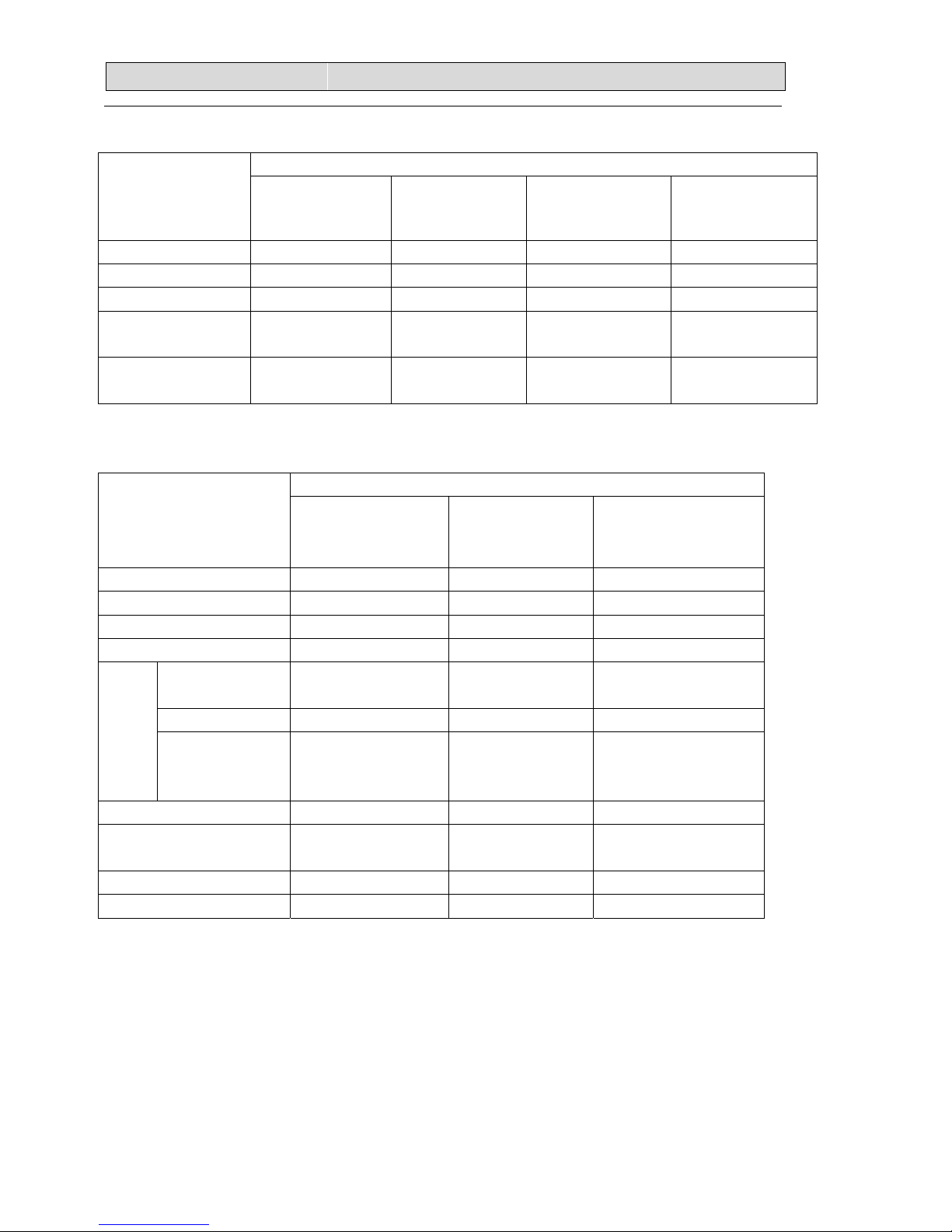
2-2-2 OUTDOOR FAN MOTOR PARAMETER
Motor model YDK70-6H-3 YDK95-6-9043 YDK55-6I-8 YDK29-6I-22
Rated power source 220V 50Hz 220V 50Hz 220V 50Hz 220V 50Hz
Phases /Poles 1/6 1/6 1/6 1/6
Rated load
output(W) 65 95 50 29
Ambient
temperature (℃) -5℃~+43℃-5℃~+50℃-5℃~+43℃-5℃~+43℃
2-3. COMPRESSOR
PARAMETER
Compressor model ATL165SD-C9AU ATL232SJNC9AU DA130S1C-20FZ
Compressor type Rotary Rotary Rotary
Rated power 1550W 2000W 990W
Current (A) 10.7 11.2 4.97
Motor type DC brushless motor DC brushless
motor DC brushless motor
Starting type DC Inverter DC Inverter DC Inverter
Motor
Winding
resistance 0.59/0.59/0.59
Ω
(at
75
℃
)
U-V/V-W/W-U
0.82/0.82/0.82
Ω
(at
75
℃
)
U-V/V-W/W-U
0.95/0.95/0.95
Ω
(at 20
℃
)
U-V/V-W/W-U
Number of cylinder 2 2 2
Oil type α68HES-H or
equivalent HAF68D1C ESTER OIL VG74
Oil charge (cc) 880 880 500
Ambient temperature(℃) -5℃~+43℃. -5℃~+43℃-5℃~+43℃

2
2.
.S
SP
PE
EC
CI
IF
FI
IC
CA
AT
TI
IO
ON
NS
S
9
2-3. Other component specifications
2-3-1. INDUCTANCE PARAMETER
Inductance model R2550HSA R2050HSB
Rated power source 220V 50Hz 220V 50Hz
Rated current(A) 25 20
Rated inductance 5.0(mH)±10% 5.2(mH)±10%
Ambient
temperature(℃) -20℃~+70℃. -20℃~+70℃.
2-3-2. FILTER
ELECTRIC
PERFORMANCE AMW3-24U4SKC
AMW4-28U4SKC
AMW3-24U4SZD
AMW3-20U4SZD
AMW4-36U4SAC AMW2-20U4SNC
AMW2-16U4SGC
Filter model RTNF-250T10X-3LF RTNF250-30T10X-3LF RTNF250-25T068X-03LF
Rated current(A) 20 30 20
Rated power
source AC 220V—50Hz AC 220V—50Hz AC 220V—50Hz
Filter frequency
range 150K—30MHz 150K—30MHz 150K—30MHz
Temperature
range(℃) -25℃~+85℃. -25℃~+85℃. -25℃~+85℃.
2-3-4. STEPPER MOTOR PARAMETER
Stepper Motor
model 24BYJ48
Voltage(DC) 12V
Number of phase 4
Drive mode 1-2phase excitation unipolar drive
Resistance per
phase 300Ω±7%
Temperature
range(℃) -10℃~+40℃
3
3.
.O
OU
UT
TL
LI
IN
NE
ES
S
A
AN
ND
D
D
DI
IM
ME
EN
NS
SI
IO
O
10
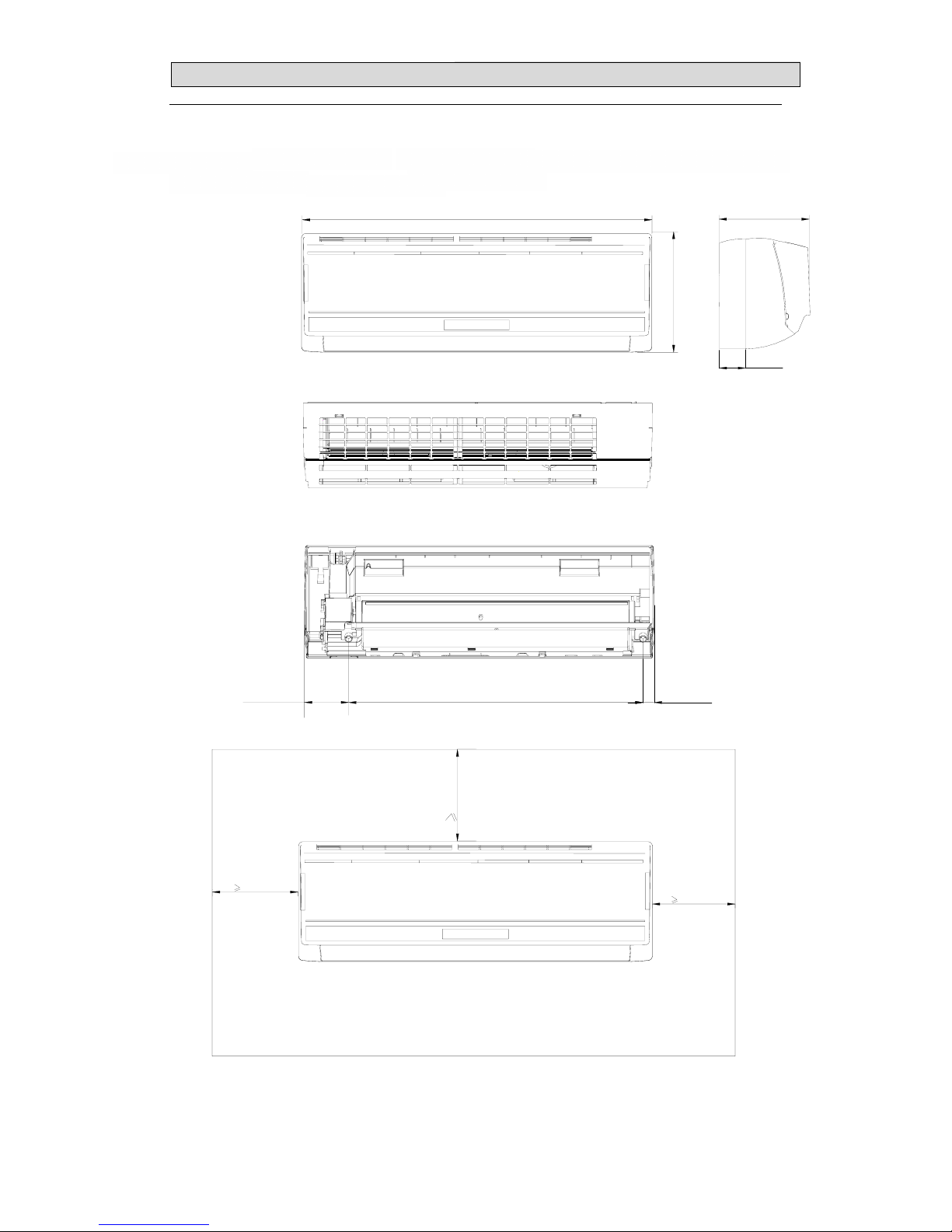
3-1. INDOOR
(MODEL: AMS-07UR4SNVG4 AMS-09UR4SNVG AMS-12UR4SNVG4(VT4、VL4、
VQ4、UP4、UL4、UQ4、NS4、ZC4、ZA4)
23mm631mm
94mm
190mm
250mm
750mm
50mm
50mm 50mm
65mm

3
3.
.O
OU
UT
TL
LI
IN
NE
ES
S
A
AN
ND
D
D
DI
IM
ME
EN
NS
SI
IO
O
14
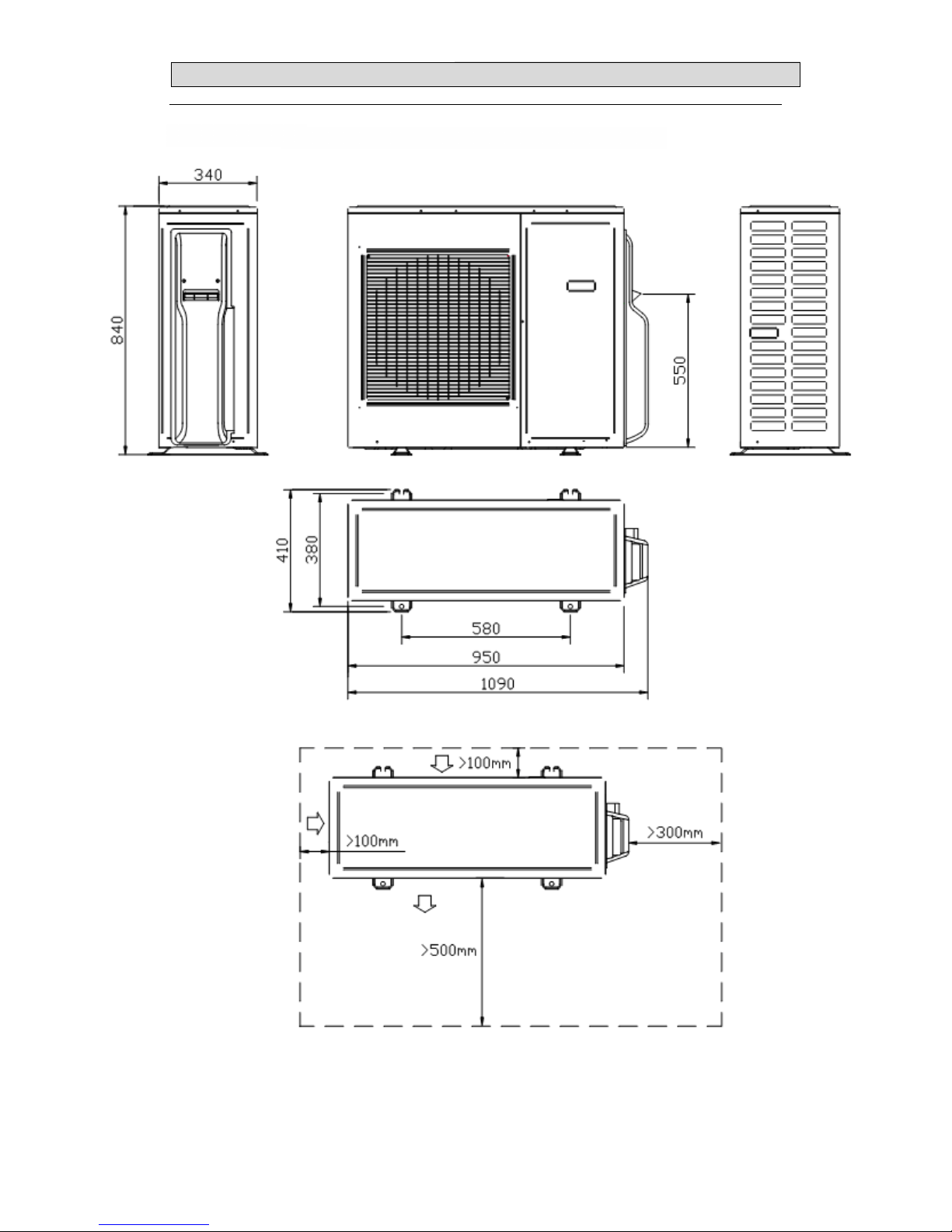
3-2.OUTDOOR
(MODEL: AMW2-16U4SGC1)

3
3.
.O
OU
UT
TL
LI
IN
NE
ES
S
A
AN
ND
D
D
DI
IM
ME
EN
NS
SI
IO
O
15
(MODEL: AMW2-20U4SNC1、AMW3-20U4SZD 、AMW3-24U4SZD)
3
3.
.O
OU
UT
TL
LI
IN
NE
ES
S
A
AN
ND
D
D
DI
IM
ME
EN
NS
SI
IO
O
16
(MODEL: AMW3-24U4SKC、AMW4-28U4SKC AMW4-36U4SAC)

4
4.
.R
RE
EF
FR
RI
IG
GE
ER
RA
AN
NT
T
F
FL
LO
OW
W
D
DI
IA
AG
GR
RA
AM
M
17
4-1. Refrigerant flow diagram :
MODEL:AMW3-24U4SKC、AMW4-28U4SKC、AMW4-36U4SAC
Filter
B机
A机
A机
C机
B机
D机
C机
D机
Remark:ThepartisonlyforAMW4-28U4SKC、AMW4-36U4SAC
COOLINGCYCLE
HEATINGCYCLE

4
4.
.
R
RE
EF
FR
RI
IG
GE
ER
RA
AN
NT
T
F
FL
LO
OW
W
D
DI
IA
AG
GR
RA
AM
M
18
MODEL:AMW3-24U4SZD 、AMW3-20U4SZD
COOLINGCYCLE
HEATING CYCLE

4
4.
.
R
RE
EF
FR
RI
IG
GE
ER
RA
AN
NT
T
F
FL
LO
OW
W
D
DI
IA
AG
GR
RA
AM
M
19
MODEL:
AMW2-16U4SGC1、AMW2-20U4SNC1
EEV B
EEV A
4-way valve
Filter
B机
A机
A机
B机Filter
4
4.
.
R
RE
EF
FR
RI
IG
GE
ER
RA
AN
NT
T
F
FL
LO
OW
W
D
DI
IA
AG
GR
RA
AM
M
20
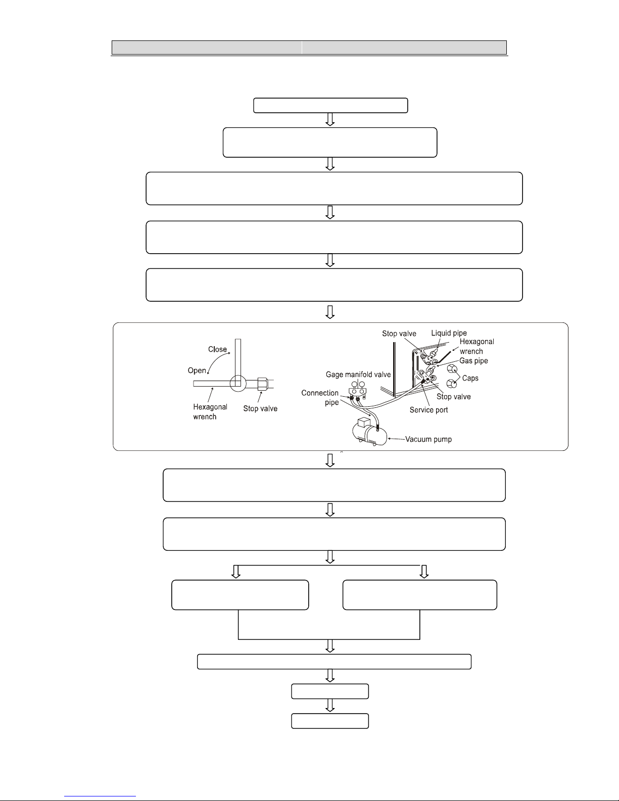
4.2 Evacuation procedures:
EVACUATION PROCEDURES
Connect the refrigerant pipes (both the liquid an
d
g
as
p
i
p
es
)
between the indoor and the outdoor units.
Remove service port cap of the stop valve A and connect gage manifold valve and vacuu
m
p
ump to it.
Run the vacuum pump for more than 15 minutes and at this time confirm that the pressure
gage indicates -0.1Mpa(-76 cmHg).
Stop pump and keep the pressure for one or two minutes. Make sure the pressure is no
change(if the pressure is changed to high, there is some leakage for the pipe connection).
Remove gage manifold valve quickly from the service port of the stop valve A.
full open the stop valvesA on gas and liquid pipe sides.
Total pipe length is in the range:
N
o gas charge is needed Total pipe length exceeding the limit:
Charge the prescribed amount of gas.
Ti
g
hten the ca
p
to the service
p
ort to obtain the initial status.
Reti
g
hten the ca
p
.
Leak test
Repeat the steps above for other valves(B\C\D), be sure all refrigerant pipes are
connected and evacuated, and all valves are full opend.

4
4.
.
R
RE
EF
FR
RI
IG
GE
ER
RA
AN
NT
T
F
FL
LO
OW
W
D
DI
IA
AG
GR
RA
AM
M
21
4-3. Evacuation direction:
MAX. Refrigerant pipe length and height difference:
Modle
AMW3-20U4SZD
AMW3-24U4SZD
AMW3-24U4SKC
AMW4-28U4SKC
AMW4-36U4SAC
AMW2-20U4SNC1
AMW2-16U4SGC1
Pipe length per. Indoor unit(a/b/c/d)25m 20m
Total pipe length for multi-system (a+b+c+d) 60m 40m
Height difference (I.D ~ O.D) 15m 15m
Height difference (I.D ~ I.D) 7.5m 7.5m
*Do your best to reduce the pipe length. Long pipe may cause capacity of the indoor unit incline.
Total refrigerant pipe length
Outdoor unit precharged 0m~20m 20m~60m
AMW3-24U4SKC 2100g 0g
AMW4-28U4SKC 2400g 0g
AMW4-36U4SAC 2600g 0g
AMW3-24U4SZD 1750g 0g
AMW3-20U4SZD 1600g 0g
Xg = 15g / m ×(Total pipe length(m) - 20)
If gas pipe include 12.7,refrigerant piping
length 20g/m
Total refrigerant pipe length
Outdoor unit precharged 0m~15m 15m~40m
AMW2-20U4SNC1 1400g
AMW2-16U4SGC1 1270g 0 Xg = 15g / m ×(Total pipe length(m) - 15)

5
5.
.
E
EL
LE
EC
CT
TR
RI
IC
CA
AL
L
D
DA
AT
TA
A
22
5-1.Electrical wiring diagrams
INDOOR:
1) AMS-07UR4SNVG4(VT、VL、VQ、UP、UL、UQ、NS、ZC、ZA)4
AMS-09UR4SNVG4(VT、VL、VQ、UP、UL、UQ、NS、ZC、ZA)4
AMS-12UR4SNVG4(VT、VL、VQ、UP、UL、UQ、NS、ZC、ZA)4

5
5.
.
E
EL
LE
EC
CT
TR
RI
IC
CA
AL
L
D
DA
AT
TA
A
23
2) AMS-18UR4SVUP3(VG3、VL3、VT3、UP3、UL3、UQ3)
This manual suits for next models
6
Table of contents
Other Shivaki Air Conditioner manuals


Popular Air Conditioner manuals by other brands

CLIMAVENETA
CLIMAVENETA a-CHD U-2T 606+2209 OPERATING AND INSTALLATION Manual

Mitsubishi Electric
Mitsubishi Electric MSC-GE20VB operating instructions

York
York YUHA 18 FS Service manual

Shinco
Shinco SPF1-10C owner's manual

Daikin
Daikin VRV III REMQ8P8Y1B installation manual

Carrier
Carrier 42TOVG010 owner's manual


Toshiba
Toshiba TCB-SIR41U-E installation manual

Hitachi
Hitachi RAS-18LH2 Service manual

Mitsubishi Electric
Mitsubishi Electric Mr. SLIM PKA-M-LAL Series installation manual

Carrier
Carrier CRTWOPOS007A00 installation instructions
 Operation manual")
Haier
Haier HW-18LMA03(T3) Operation manual

Daikin
Daikin FXSN20AV1 Operation manual