Shively Labs 6810 Owner's manual

Circularly Polarized FM
Broadcast Antenna
Model 6810
Instruction Manual
Installation, Operation, &
Maintenance

2
Congratulations! Thank you for purchasing one of the finest FM broadcast antennas on the
market today. The Shively Labs Model 6810 is widely recognized as the top-of-
the-line in its class for its superior performance and durability.
Your purchase is backed by the best technical support in the industry. Shively
is a leading manufacturer in the broadcast industry, providing an extensive
range of antennas, transmission line and components. Our technical staff has
a wealth of experience in the broadcast industry and is standing by to serve
you in any way.
This manual is intended to give you a good basic understanding of your
antenna: its proper and safe installation, startup, and operation, and trouble-
shooting and maintenance information to keep it working satisfactorily for
years to come.
Please have everyone involved with the antenna read this
manual carefully, and keep it handy for future reference.
Meanwhile, please feel free to contact your sales representative at Shively
Labs at any time if you need information or help. Call or write:
Publication No. im-6810 (150521)

IMPORTANT
Please read this manual in its entirety before beginning
installation of your antenna!
Failure to follow the installation and operation
instructions in this manual could lead to failure of your
equipment and might even void your warranty!


i
Table of Contents
Chapter 1 Precautions and Preparation.............................................1
Precautions...........................................................................................1
Receiving..............................................................................................1
Unpacking ............................................................................................1
Checking the system .............................................................................2
Chapter 2 Antenna Installation..........................................................3
Precautions...........................................................................................3
Study your antenna...............................................................................3
Install the back support mounts ............................................................4
Figure 1 Attach the back support mount ..........................................4
Install the bay radiators.........................................................................5
Figure 2 Attach bay radiator............................................................ 6
Figure 3 Flange hardware tightening sequence................................. 7
Table 1 Torque specifications, flange bolts....................................... 7
Install standard radomes (if applicable) ..................................................7
Figure 4 Standard radome installation.............................................. 8
Install XXL radomes
(if applicable).....................................................................9
Figure 5 XXL radome installation
(radome, closure plates and ground straps) ...................... 11
Figure 6 XXL radome installation (backplate and bay radiator)......... 12
Figure 7 XXL radome installation (tower mounts)............................ 13
Installing the feedline assemblies on the tower .....................................14
Figure 8 Common feedline mount configurations ............................ 15
Figure 9 Feedline flange detail....................................................... 16
Installing the transformer ....................................................................17
Figure 10 Transformer Installation, top view .................................. 17
Installing parasitic elements
(if applicable)...................................................................17
Chapter 3 De-Icer Installation (if applicable)..................................19
De-icer description ..............................................................................19
Before beginning de-icer installation..................................................... 19
Installation procedure.......................................................................... 20
De-icer installation.........................................................................20
Figure 11 De-icer system schematic diagram, overall ...................... 21
Figure 12 Bay junction box installation........................................... 22
Figure 13 Shively de-icer control box layout ................................... 23
Thermostat installation (if applicable) .............................................23
Table 2 De-icer specifications ....................................................... 24
Table 3 Single thermostat readings ............................................... 24
Table 4 Tandem thermostat readings ............................................ 25

ii
Table of Contents
Chapter 4 Startup and Operation.....................................................27
Precautions......................................................................................... 27
Pressurization ..................................................................................... 27
Test for leaks................................................................................27
Purge the system .......................................................................... 27
Figure 14 Pressurized gas schematic.............................................. 28
Table 5 Volume of coax per 1000 feet of length.............................. 29
Leave the system pressurized......................................................... 29
Impedance trimming........................................................................... 30
Figure 15 Impedance-matching transformer................................... 30
Table 6 Factory control rod settings............................................... 30
System sweep (recommended) ............................................................ 31
Checkout............................................................................................ 31
Antenna operation...............................................................................32
De-icer system operation.....................................................................32
Shively Labs de-icer control system ................................................32
Chapter 5 Maintenance ....................................................................33
Precautions......................................................................................... 33
Maintenance log..................................................................................33
Physical inspection ..............................................................................33
De-Icer check ..................................................................................... 34
Paint..................................................................................................34
Radiator removal for repair..................................................................34
Return policy ......................................................................................34
Troubleshooting..................................................................................34
Internal arcing .............................................................................. 34
Broad spectrum RF noise ............................................................... 34
High VSWR at startup or during operation.......................................35
Erratic VSWR during impedance trimming ....................................... 35
Change in coverage.......................................................................35
Pressure loss or excessive gas usage ..............................................36
Sample maintenance log......................................................................37

1
Precautions and Preparation
1 Precautions and Preparation
Precautions WARNING
Don't expose personnel to the medical hazards of intense radio fre-
quency (RF) radiation. Whenever working on the tower in the area of
the antenna, turn off all transmitters and lock them out so that they can-
not be turned on accidentally.
For reference on RF safety, see CFR 29, Section 1910.97, the OSHA standard
for exposure to non-ionizing radiation.
Receiving As soon as you receive your antenna,
BEFORE
signing for the shipment:
a. Check to be sure all the material has arrived.
NOTE
The box number and the total number of boxes are marked on each box;
for example, “Box 2 of 5” means “box number 2 of a total of five boxes.”
b. Check for evident damage to any of the boxes.
c. If any boxes are missing, or if any are obviously damaged, describe the
problem in a WRITTEN note on the shipping papers BEFORE signing them.
Then call Shively right away, and we’ll do everything we can to correct the
situation.
Important!
Never store the antenna system outdoors, boxed or otherwise. Take
pains to keep the antenna components dry. You will need to purge mois-
ture from the interior of the antenna components before applying trans-
mitter power, and purging will be much more time-consuming if the
components get wet.
Unpacking a. Find Box 1; it is marked “Open This Box First.” It contains the transformer
and two copies of the installation drawing. The parts list on one sheet of the
installation drawing shows what box each item is in.
b. Then open the boxes and examine for shipping damages. File any necessary
claims with the carrier immediately.
c. If all the boxes are present and in good condition but material seems to be
missing, please contact Shively Labs immediately, using the telephone or Fax
number on the inside cover of this manual. For the best service, have our
shop order number (S/O) handy; it's in the block at the bottom right corner
of the installation drawing.
d. Along with your antenna you will get a spare parts kit. Place this in a safe
place until it is needed.
CAUTION
All contact surfaces and openings to the interior of the components are
protected from contamination and from physical damage by caps and
plastic bags. Do not remove this protection until ready to connect the
components.

Precautions and Preparation
2
Checking the system Shively has planned the installation of the antenna based upon information
provided by you. If this information contained errors, the parts and mounting
hardware will have been designed incorrectly and will cause expensive delays
in installation.
Therefore, we recommend that you recheck the installation
parameters during this planning stage.
Check all the parts to be sure that they will fit the tower and each other. Study
the installation drawings carefully to confirm that the information used in
designing the antenna and mounts was, in fact, accurate.
Have a reliable tower person, familiar with antennas and coaxial line, inspect
the tower and review the installation drawings before the full rigging crew
arrives.
If design problems are found, contact Shively Labs immediately. Pay particu-
lar attention to:
• Frequency of the antenna.
• Fit of the mounts to the tower members.
• Freedom from interference by gussets, leg flanges, guys and their
attachment points, tower face members, obstruction lights, and
other components.
• Compatibility of transmission line and antenna input terminals.
• Location of the transmission line run relative to the antenna input
terminal.
• Use of non-metallic guy sections on the tower in the region to be
occupied by the FM antenna. Ensure that there are no metal guys
within ten feet (three meters) of any radiator.
• Availability of proper electrical service for de-icers, if applicable.
• The adequacy of the tower structure and guys to carry the wind-
load placed upon them by the antenna, particularly if radomes are
used.
You gave Shively this information at the time of purchase, but a last check at
this time can catch an error, which will be easier to correct before installation
begins.
Remember!
It is YOUR responsibility to
ensure that your installa-
tion meets all applicable
codes and the centerline-
of-radiation requirements
of your FCC construction
permit.

3
Antenna Installation
2 Antenna Installation
Precautions WARNING
Don't expose personnel to the medical hazards of intense radio fre-
quency (RF) radiation. Whenever working on the tower in the area of
the antenna, turn off all transmitters and lock them out so that they can-
not be turned on accidentally.
WARNING
Material safety data sheets for the chemicals you may encounter are
appended at the end of this manual. Study them carefully before begin-
ning installation.
CAUTION
O-rings are made of silicone. Do not lubricate them with silicone grease,
as this will soften the O-ring. Use only a light lubricating coat of O-Lube
(provided) or petroleum jelly; too much may hamper electrical contact
and contaminate the interior of the system.
CAUTION
Feedstrap orientation is critical to performance. In general, the feed-
straps in a full-wave-spaced antenna will all be oriented the same, while
those in a half-wave-spaced antenna will alternate.
Install each radiator
in accordance with its stenciled bay numbers and its "up-arrow" sticker.
Study your antenna CAUTION
These procedures are guidelines. Assemble components exactly in
accordance with the installation drawing. If you don’t, the antenna may
not perform as expected.
It will be easiest to mount the radiators, feedline mounts, and radomes (if
applicable) onto the feedline sections before the feedline sections are
mounted on the tower.
Determine what, if any, icing protection your antenna has.
If your antenna element looks like Figure 2 on page 6 (white partial radome):
• Continue with Install the back support mounts on page 4.
• Then Install the bay radiators on page 5.
If your radomes look like Figure 4 on page 8 (standard radomes):
•PerformInstall the back support mounts on page 4.
•PerformInstall the bay radiators on page 5.
• Then go to Install standard radomes (if applicable) on page 7.
If your radomes look like Figure 7 on page 13 (XXL radomes):
•PerformInstall the bay radiators on page 5.
• Then go to Install XXL radomes (if applicable) on page 9.
If your antenna has de-icers:
• Continue with Install the back support mounts on page 4.
• Then Install the bay radiators on page 5.
• Then go to Chapter 3 for de-icer installation.

Antenna Installation
4
Install the back
support mounts a. Pair up the feedline sections and the radiator assemblies, using the bay
number stenciled on each piece.
Important
This back support mount is NOT used with XXL radomes!
b. Attach the back support mount to the feedline:
(1) Lay a feedline section horizontally, supported off the ground, with its
baymount flange pointing downward.
(2) Study your installation drawing. There is a detail identifying the correct
azimuth rotation of the antenna bays from the tower mounting surface.
(3) Now look at the feedline, with its upper and lower mount flanges. The
upper feedline mount flange has a series of notches cut into it (Figure
1). The center notch is exactly opposite the baymount flange. Each
notch represents five degrees (5°) of azimuth rotation. Align the
centered mark on the back support mount to the notch representing the
azimuth rotation identified on the installation drawing.
Figure 1. Attach the back
support mount

5
Antenna Installation
(4) Using a hardware mounting kit (four bolts with nuts and washers),
secure the back support mount to the upper feedline mount flange and
lower feedline mount flange.
NOTE
Use shims or washers as necessary to fit the back support mount to the
mount flanges.
NOTE
You may need to save final tightening of this hardware until the feedline
is installed on the tower.
c. Repeat the above steps for the remaining feedline sections.
Install the bay
radiators a. Attach the bay radiator to the feedline (Figure 2):
(1) Roll the feedline section over so that the baymount flange points
upward. Secure the feedline section at the brass end, using clamps, to
prevent its turning with the weight of the radiator.
CAUTION
All contact surfaces and openings to the interior of the components are
protected from contamination and from physical damage by protective
covers and plastic bags. Do not remove this protection until ready to
connect the components.
(2) Remove the plastic bag and protective cover from the baymount flange.
(3) Make sure an inner conductor connector is in place in the inner
conductor of the baymount flange of the feedline.
NOTE
Feedline flange hardware and O-ring are shipped separately in a plastic
bag. Each bag contains the hardware and O-ring for one flange.
CAUTION
Be sure the baymount flange O-ring is properly seated in its groove and
not pinched between the flange contact surfaces.
(4) Coat the baymount flange O-ring lightly with O-Lube (supplied with the
antenna), then install it in the O-ring groove in the baymount flange.
(5) Remove the matching radiator assembly from its protective plastic bag.
CAUTION
Be sure the radiator’s inner conductor fits cleanly over the baymount’s
inner conductor connector. If any of the fingers of the connector are
forced outside the radiator’s inner conductor (we call this a "split bul-
let"), this will cause arcing and damage to the antenna.
(6) Align the radiator with the baymount flange as shown, with the top of
the radiator pointing toward the top of the feedline. Carefully place the
radiator into position over the flange studs and inner conductor
connector.
(7) First snug the baymount flange hardware, then tighten in the sequence
shown in Figure 3. Torque in accordance with Table 1 on page 7.
Important
Be very careful not to dis-
turb or damage the feed
strap when handling the
bay radiator.

Antenna Installation
6
Figure 2. Attach bay radiator
b. Clamp the mounting saddle to the feedline, using a band clamp.
NOTE
The bay saddle is only used
on radiators with partial
radomes, as shown in Fig-
ure 2. See Figure 4 or Fig-
ure 6 for installation of
radiators with standard or
XXL radomes.

7
Antenna Installation
c. The partial radome closure plates are shipped separately. Install them over
the end seal, using the hardware provided.
d. Repeat the above steps for the remaining feedline sections.
Figure 3. Flange hardware
tightening sequence
Install standard
radomes (if applicable) If your system includes standard radomes, you can most easily install them on
the ground following completion of Install the back support mounts and Install
the bay radiators. See Figure 4 on page 8.
NOTE
Radome match-markings bear no relation to radiator and feedline mark-
ings. Install any radome on any bay.
Radome halves are match-marked in pairs (A-A, B-B, etc.). In order to align
the flange bolt holes, be sure to pair them according to their match-markings.
a. Select a pair of radome halves match-marked with the same letter
designation (A and A, B and B, etc.). The top (1) and bottom (2) radome
halves include the radome-mounted halves (3) and (4) of the radome
mounting brackets.
b. Open the hardware kit. The kit contains:
• hardware (5), 1/4-20, for the radome flanges,
• hardware (6) to join the radome mounting bracket halves, and
• hardware (7) to secure the mounting brackets to the feedline
mount flange (8),
• the flange-mounted halves (9) and (10) of the mounting brackets.
Table 1. Torque specifications, flange bolts
Transmission Line Size Bolt Size Torque
1-5/8" 5/16-18 10 ft-lb 13 N-m
2-1/8" 3/8-16 16 ft-lb 23 N-m
3-1/8" 3/8-16 16 ft-lb 23 N-m
4-1/16" 3/8-16 16 ft-lb 23 N-m

Antenna Installation
8
Figure 4. Standard radome
installation
1Top radome half 7Bracket mounting hardware
2Bottom radome half 8Feedline mount flange
3Top radome bracket 9Top radome bracket
4Bottom radome bracket 10 Bottom radome bracket
5Radome flange hardware 11 Bay radiator
6Radome bracket hardware 12 Baymount

9
Antenna Installation
c. Identify the top radome half (1) by its wide, overlapping mating flange and
the bottom radome half (2) by its narrow mating flange and drain holes.
d. Install the top radome half:
NOTE
Each radome half has a double notch under the mount; the larger outer
notch fits over the feedline and the smaller inner notch fits against the
baymount.
(1) Carefully place the top radome half in place, slipping it behind the
radiator (11) and up against the baymount (12).
(2) Loosely attach the flange-mounted bracket half (9) of the top radome
mount to the feedline mount flange (8).
(3) Loosely install the hardware (6) to secure the mounting bracket halves
together.
e. Install the bottom radome half:
(1) Carefully place the bottom radome half (2) in place, slipping it behind
the radiator (11) and up against the baymount (12), with its flange
inside the larger flange of the upper radome half.
(2) Loosely attach the flange-mounted bracket half (10) of the bottom
radome mount to the feedline mount flange (8).
(3) Loosely install the hardware (6) to secure the mounting bracket halves
together.
NOTE
You may have to squeeze the radome flanges together slightly with a
clamp to start the nuts. Get all these nuts and bolts in place before tight-
ening them.
(4) Fasten the two radome halves together loosely with the radome flange
hardware (5), starting near the feedline and working around both sides
to the outer edge. It may be necessary to squeeze the radome flanges
together to start the nuts.
f. Once all hardware is in place, tighten all hardware securely.
g. Seal the joint where the radome encircles the baymount with the silicone
sealant supplied with the antenna.
Important
Be very careful to seal the joint completely. If water enters the radome,
the antenna will not perform as expected, and may cause damage to
your entire system.
Install XXL radomes
(if applicable) If your system includes XXL radomes, you can most easily install them on the
ground. See Figure 6 on page 12, Figure 5 on page 11, and Figure 7 on page
13.
Radome halves are match-marked in pairs (A-A, B-B, etc.). In order to align
the flange bolt holes, be sure to pair them according to their match-markings.
NOTE
Radome match-markings bear no relation to radiator and feedline mark-
ings. Install any radome on any bay.
a. Unpack the radomes:

Antenna Installation
10
(1) Each radome is shipped partially assembled on its own pallet.
Disassemble the radome halves and the radome mounts.
(2) Identify the top radome half (1) by its wide mating flange and the
bottom radome half (2) by its narrow mating flange and drain holes.
(3) Separate the radome halves, keeping the 1/4" radome flange hardware
(3) for installation.
(4) Remove the closure plate hardware (4) at the edges where the mount
will slip under the closure plates. Loosen the other closure plate
hardware (5) and leave the top closure plate (6) and bottom closure
plate (7) in place on the radomes.
b. Install the radome backplate:
NOTE
With XXL radomes, antenna azimuth is controlled by the design of the
tower mounts. No further alignment by the installer is necessary.
(1) Locate the radome backplate (8) on the feedline (9) as shown, exactly
opposite the baymount flange (10).
NOTE
Use shims or washers (11) as necessary to fit the back support mount to
the mount flanges.
(2) Bolt the radome backplate to the feedline mount flange, using the 3/8"
backplate hardware (12).
c. Install the bay radiator:
(1) Install a lightly lubricated O-ring (13) into the O-ring groove in the
baymount flange.
(2) Install the radiator (14) onto the baymount flange, making sure the
O-ring remains within the groove and is not pinched between the flange
surfaces.
(3) Secure the radiator using the baymount hardware (15).
d. Install the radome:
(1) Place the top radome half (1) over the radiator (14) and feedline (9) and
into the backplate (8), slipping the ends of the radome backplate under
the top closure plate (6).
(2) Place the bottom radome half (2) over the radiator and feedline and into
the backplate and top radome half, inserting the end of the radome
backplate under the bottom closure plate (7).
(3) Bolt the radome halves loosely to the backplate with the radome-
backplate hardware (16).
NOTE
You may have to squeeze the radome flanges together slightly with a
clamp to start the nuts. Get all these nuts and bolts in place before tight-
ening them.
(4) Fasten the two radome halves together with the 1/4" radome flange
hardware (3), starting at the feedline side and working around both
sides to the outer edge. Tighten the radome flange hardware.

11
Antenna Installation
Figure 5. XXL radome
installation
(radome, closure plates and
ground straps)
1Top radome half 8Backplate
2Bottom radome half 9Feedline
3Radome flange hardware 14 Bay radiator
4Closure plate hardware 16 Radome-backplate hardware
5Closure plate hardware 17 Top ground strap
6Top closure plate 18 Band clamp (2)
7Bottom closure plate 19 Bottom ground strap

Antenna Installation
12
Figure 6. XXL radome
installation (backplate and bay
radiator)
e. Install the closure plates and ground straps:
(1) Install the top closure plate hardware (4) through the the top ground
strap (17), closure plate (6), and into the threaded hole in the top of
the radome (1).
8Radome backplate 12 Backplate hardware
9Feedline 13 O-ring
10 Baymount flange 14 Bay radiator
11 Shims or washers as needed 15 Baymount hardware

13
Antenna Installation
Figure 7. XXL radome installation
(tower mounts)
(2) Secure the ground strap to the feedline (9) - see detail in Figure 7 -
using the band clamp (18).
(3) Repeat for the bottom closure plate (7) and the bottom groundstrap
(19).
f. Tighten the closure plate hardware (4) and (5) and the radome-backplate
hardware (16).
1Top radome half 18 Band clamp (2)
2Bottom radome half 19 Bottom ground strap
8Backplate 20 Tower mounts (2)
9Feedline 21 Box bolts or 1/2" hardware (8)
17 Top ground strap

Important
Be very careful to seal the radome completely. If water enters the
radome, the antenna will not perform as expected, and may cause dam-
age to your entire system.
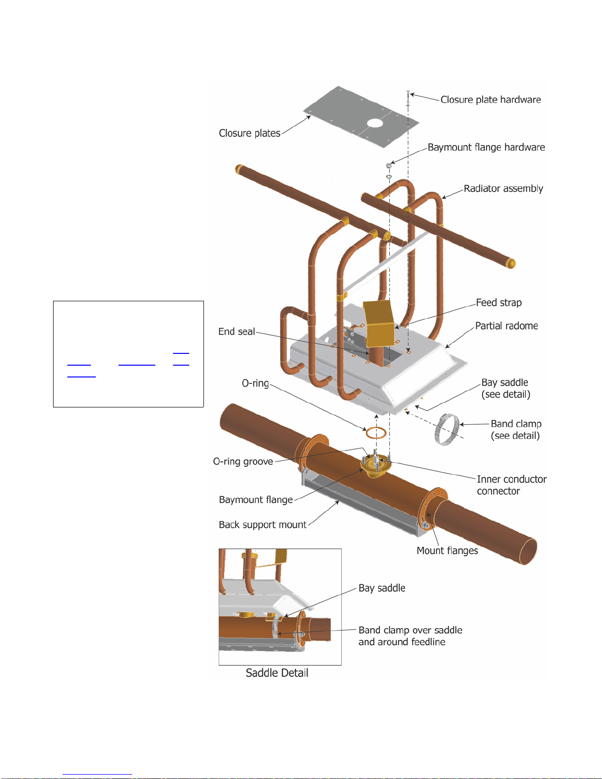
g. Seal the closure plates and the joints where the radome meets the backplate
with the silicone sealant supplied with the antenna.
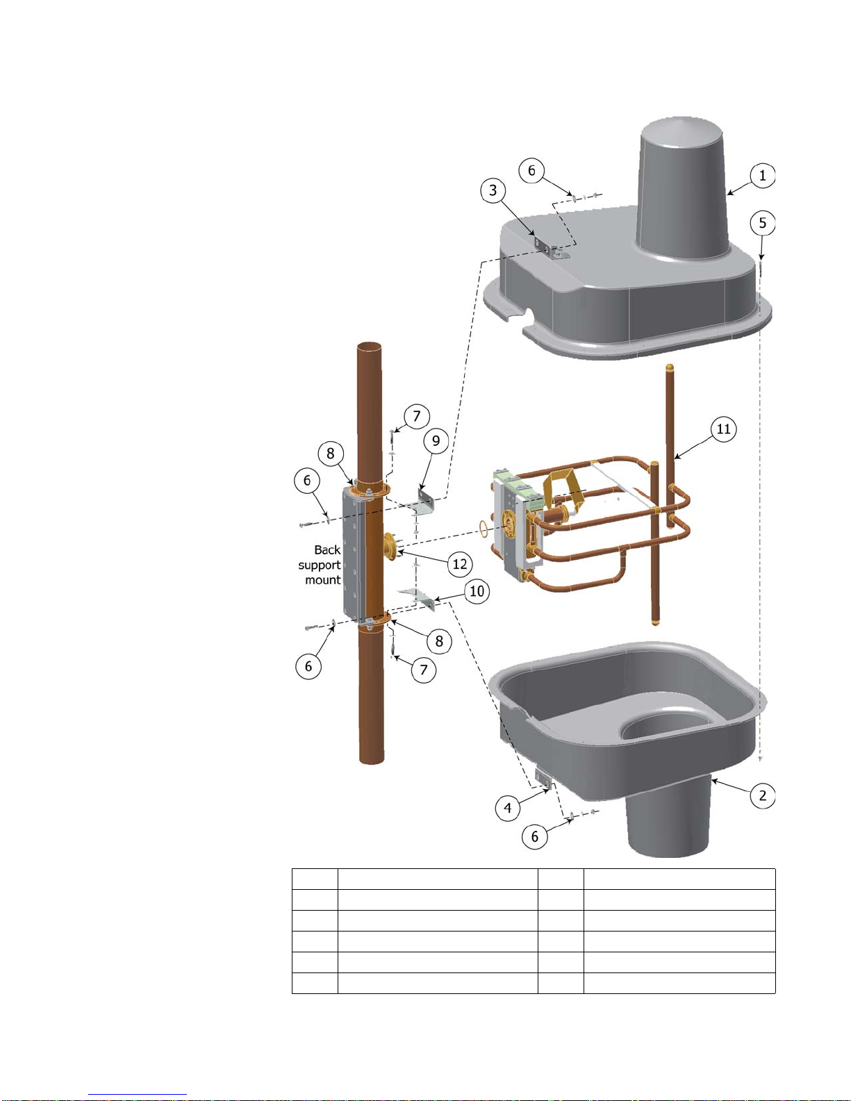
h. Install the tower mounts (20) onto the backplate, using the box bolts (21).
Manufacturer instructions for the box bolts are included.
Installing the feedline
assemblies on the
tower
Feedline mounts vary from installation to installation, to accomodate various
tower and mounting pole requirements. Figure 8 shows several common con-
figurations. Your feedline mounts may be one of the common designs shown;
if they are not, they will be shown in detail on your installation drawing.
Before you begin installation, study the mounts, the mounting tower leg(s) or
pole, and your installation drawing carefully, to determine which mount(s) will
be used for each component.
a. Prepare the tower for mounts:
(1) On the tower, starting at the top, use a steel measuring tape to find the
location of each bay in accordance with the installation drawing. Mark
the mount locations.
(2) Mark the specified location of any accessory mounts, such as for the
transformer or special coax input line sections, to make sure they will
fit as planned.
(3) Watch carefully for any interferences by tower members or guy wires
which were not accounted for in the design.
(4) Where the mounts will be in contact with the tower leg(s) or mounting
pole, scrape the tower paint away to ensure good electrical contact.
b. Install the feedline sections:
CAUTION
Feedline flanges are match-marked. Assemble components in accor-
dance with their match-markings (see Figure 9) and the installation
drawing. If you don’t, the antenna will not perform as expected.
CAUTION
Secure each feedline section to its mount before installing the next sec-
tion, tightening in accordance with Figure 3 and Table 1.
(1) Starting at the top of the antenna array, install the feedline and feedline
mounts carefully, in accordance with your installation drawing and the
illustrations in this chapter.
Important!
To avoid damage to the
antenna, always lift, posi-
tion, and attach each sec-
tion individually. Never try
to transport connected
feedline sections! Feedline
is not designed to support
multiple sections and
damage will occur.
Important!
Remove the tower paint
to ensure good electrical
contact between the
mounts and the tower. If
you don’t get good con-
tact, the antenna may not
perform as designed, and
may produce stray signals
that will interfere with
other services on the
tower.
Other manuals for 6810
1
Table of contents
Other Shively Labs Antenna manuals

Shively Labs
Shively Labs 6842 Owner's manual

Shively Labs
Shively Labs 6017 User manual

Shively Labs
Shively Labs 6814 User manual

Shively Labs
Shively Labs 6020 Instruction Manual

Shively Labs
Shively Labs 6600 User manual

Shively Labs
Shively Labs 6822 Owner's manual

Shively Labs
Shively Labs 6810 Operating and safety instructions

Shively Labs
Shively Labs 6812DIN Owner's manual

Shively Labs
Shively Labs 6812B Owner's manual

Shively Labs
Shively Labs Versa2une SLV User manual