Shively Labs 6812B Owner's manual
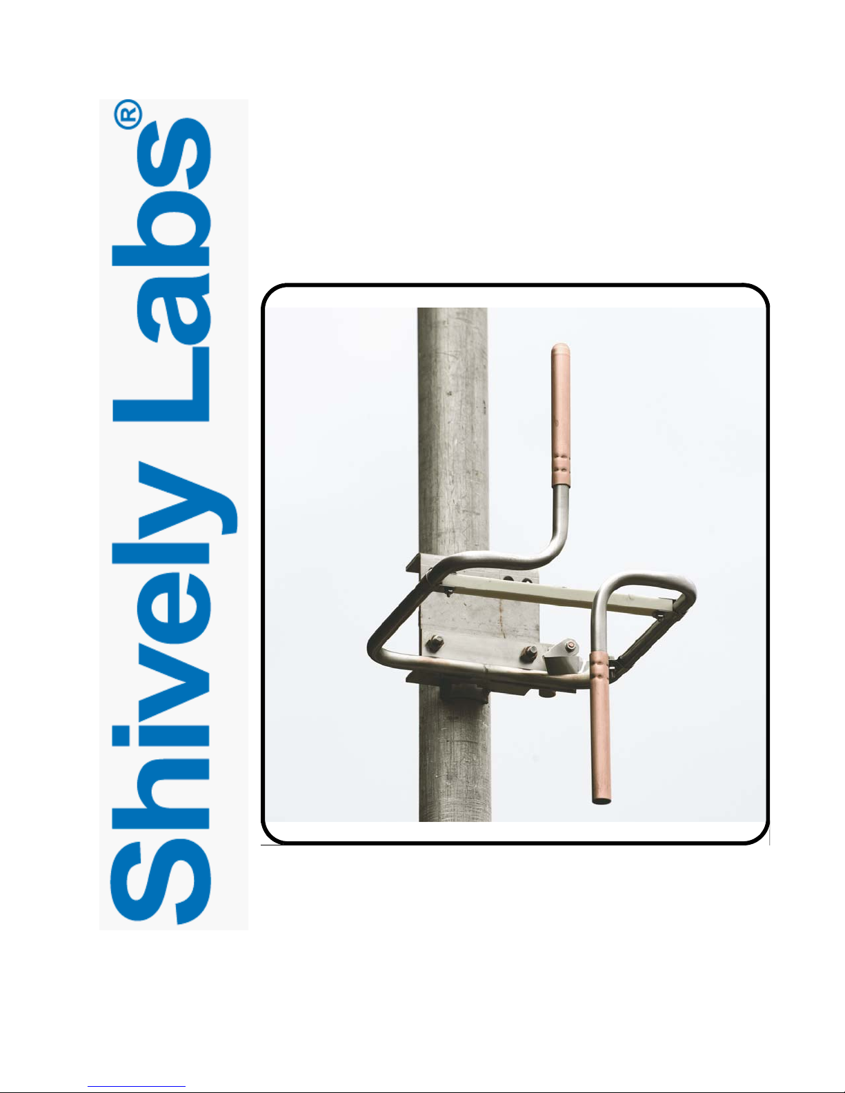
Circularly Polarized FM
Broadcast Antenna
Model 6812B
Instruction Manual
Installation, Operation, &
Maintenance

2
Congratulations! Thank you for purchasing one of the finest FM broadcast antennas on the
market today. The Shively Labs Model 6812B is widely recognized as the top-
of-the-line in its class for its superior performance and durability.
Your purchase is backed by the best technical support in the industry. Shively
is a leading manufacturer in the broadcast industry, providing an extensive
range of antennas, filters, transmission line and components. Our technical
staff has a wealth of experience in the broadcast industry and is standing by
to serve you in any way.
This manual is intended to give you a basic understanding of your antenna:
its proper and safe installation, startup, and operation, and troubleshooting
and maintenance information to keep it working satisfactorily for years to
come.
Please have everyone involved with the antenna read this manual care-
fully, and keep it handy for future reference.
Meanwhile, please feel free to contact your sales representative at Shively
Labs at any time if you need information or help. Call or write:
Publication No. im6812B (170516)

IMPORTANT
Please read this manual in its entirety before beginning
installation of your antenna!
Failure to follow the installation and operation
instructions in this manual could lead to failure of your
equipment and might even void your warranty!


i
Table of Contents Chapter 1 Precautions and Preparation ............................................. 1
Precautions........................................................................................... 1
Check the System ................................................................................. 1
Storage prior to installation.................................................................... 1
Bay spacing .......................................................................................... 2
Table 1 Bay spacing chart ............................................................... 2
Bolt tightening ...................................................................................... 2
Table 2 Torque specifications .......................................................... 2
Chapter 2 Antenna Installation..........................................................3
Precautions........................................................................................... 3
Installing the support pipe ..................................................................... 3
Figure 1 Support pipe installation .................................................... 3
Table 3 Side-mounted support pipe standoff from tower ................... 3
Installing the radiators........................................................................... 4
Figure 2 Formed mount channel ...................................................... 4
Figure 3 Installation of radiator without radome, exploded view......... 5
Figure 4 Radome backplate installation ............................................ 5
Figure 5 Installation of radiator with radome, exploded view ............. 6
Installing the interbay cable harness....................................................... 6
Figure 6 Installation of top and bottom bays .................................... 7
Figure 7 Wrapping and securing the interbay cables ......................... 8
Figure 8 Proper and improper application of splicing tape.................. 9
Chapter 3 Installing the De-icer System (if applicable)...................11
Precautions......................................................................................... 11
De-icer system description ................................................................... 11
Figure 9 De-Icer electrical schematic diagram................................. 12
Table 4 De-Icer specifications ....................................................... 13
De-icer installation .............................................................................. 13
Figure 10 Bay junction box installation ........................................... 14
Table 5 Thermostat readings......................................................... 15
Chapter 4 Startup and Operation .....................................................17
Precautions......................................................................................... 17
The antenna ....................................................................................... 17
The de-icer system.............................................................................. 17
Chapter 5 Maintenance and Troubleshooting ..................................19
Precautions......................................................................................... 19
Maintenance log.................................................................................. 19
Physical inspection .............................................................................. 19
Paint .................................................................................................. 19
Radome removal and reinstallation....................................................... 19
Return policy ...................................................................................... 20
Troubleshooting .................................................................................. 20
Sample maintenance log...................................................................... 22


1
Precautions and Preparation
1 Precautions and Preparation
Precautions WARNING
Don't expose personnel to the medical hazards of intense radio fre-
quency (RF) radiation. Whenever working on the tower in the area of
the antenna, turn off all transmitters and lock them out so that they can-
not be turned on accidentally.
For reference on RF safety, see CFR 29, Section 1910.97, the OSHA standard
for exposure to non-ionizing radiation.
Check the System CAUTION
It is YOUR responsibility to ensure that your installation meets all appli-
cable codes and the centerline-of-radiation requirements of your FCC
construction permit.
Check the parts to be sure that they will fit the support pipe. Have a reliable
tower person, familiar with antennas and coaxial line, inspect the tower and
review the installation drawings before the full rigging crew arrives. If design
problems are found, contact Shively Labs immediately.
Pay particular attention to:
• Frequency of the antenna.
• Freedom from interference by gussets, leg flanges, guy wires and
their attachment points, tower face members, obstruction lights,
and other components.
• Compatibility of coax connectors and antenna input terminals.
• Use of non-metallic guy sections on the tower in the region to be
occupied by the FM antenna. Ensure that there are no metal guy
wires within ten feet (three meters) of any radiator.
• Proper electrical service for antenna deicers, if applicable.
• The adequacy of the tower structure and guy wires to carry the
windload placed upon them by the antenna, particularly if radomes
are used.
Storage prior to
installation
Keep the antenna system dry. Never store it outdoors. If the antenna gets
wet, you will need to dry it before applying transmitter power.
Precautions and Preparation
2
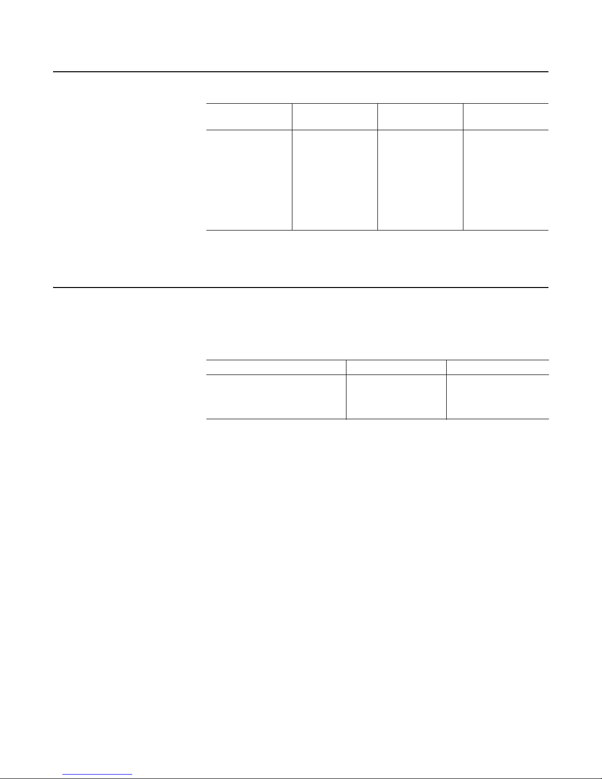
Bay spacing
Special spacing example:
For an antenna at 99.3 MHz and 0.75 spacing:
11803 x 0.75 / 99.3 = 89.146 inches spacing; round to 89-1/8".
Bolt tightening NOTE
Use an anti-seize compound to minimize galling on stainless steel
threads.
Table 1. Bay spacing chart
Frequency "0.85-Wave"
Spacing
"Half-Wave"
Spacing
Special
Spacing
88 - 98 MHz
("Low-Band")
108 in
(2.74 m)
63-1/2 in
(1.61 m)
11803 x spacing
÷ frequency ;
round to closest
1/8"
98 - 108 MHz
("High-Band")
98 in
(2.49 m)
57 in
(1.45 m)
11803 x spacing
÷ frequency ;
round to closest
1/8"
Table 2. Torque specifications
Hardware size Torque (dry) Torque (lubricated)
1/4-20 (radome flanges) 75.2 in-lbf (8.5 N-m) 63.9 in-lbf (7.2 N-m)
5/16-18 (1-5/8" EIA flanges) 132 in-lbf (14.9 N-m) 112 in-lbf (12.7 N-m)
3/8-16 (3-1/8" EIA flanges) 236 in-lbf (26.7 N-m) 201 in-lbf (22.7 N-m)
3
Antenna Installation
2 Antenna Installation
Precautions WARNING
Don't expose personnel to the medical hazards of intense radio fre-
quency (RF) radiation. Whenever working on the tower in the area of
the antenna, turn off all transmitters and lock them out so that they can-
not be turned on accidentally.
Installing the support
pipe
The 6812B antenna is designed to mount on a customer-supplied vertical pipe,
which in turn is mounted on the tower. Mounting is a little different for side-
mounted poles and top-mounted poles.
The pipe must be between 2-3/8” and 3-1/2” (60 and 89 mm) nominal out-
side diameter. It must extend at least five feet (1500 mm) above the top bay
and five feet below the bottom bay.
NOTE
Shively can accommodate other pipe sizes if necessary by special order.
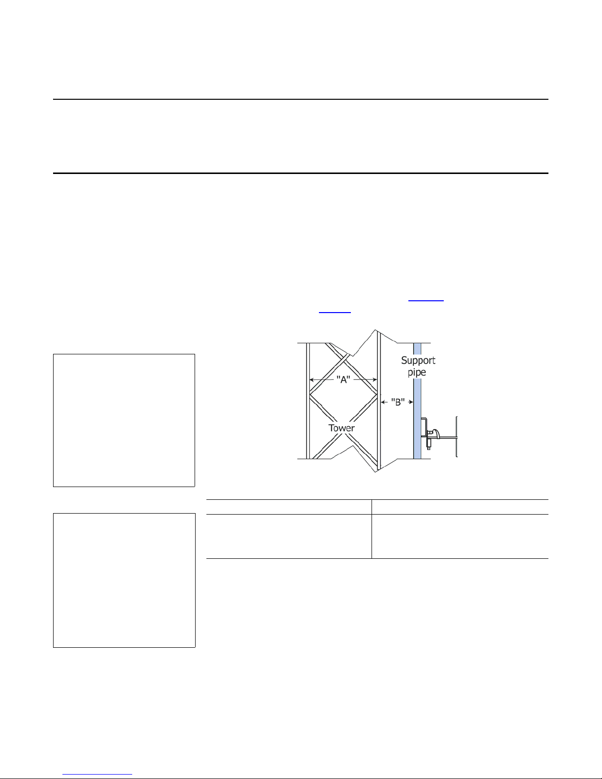
Side-mounted support pipe Mount your support pipe securely as shown in Figure 1. It must stand off from
the tower as described in Table 3.
Figure 1. Support pipe
installation
Follow these guidelines:
a. To ensure good electrical contact between the support pipe and the tower,
remove the tower paint and any rust at the support pipe mount locations
before installing the mounts. After installing the mounts, be sure to touch up
the paint where you removed it.
b. Starting at the top of the support pipe, mark the location of each bay in
accordance with the installation drawing.
c. Also, mark the specified location of any accessory mounts (eg: de-icer box
mounts), to make sure they will fit as planned.
Table 3. Side-mounted support pipe standoff from tower
Tower Face "A" Standoff "B"
less than 24" (610 mm) 12" (305 mm)
24" - 60" (610 - 1500 mm) 24" (610 mm)
over 60" (1500 mm) 36" (915 mm)
CAUTION
If you don't get good elec-
trical contact between the
mounts, the support pipe,
and the tower, the
antenna may not perform
as designed and may pro-
duce stray signals that will
interfere with other ser-
vices on the tower.
Important
Improper antenna mount-
ing is a leading cause of
poor performance in
6812B antennas. It is
very important to install
the antenna as indicated
and to position it away
from other metallic struc-
tures.

Antenna Installation
4
Top-mounted support pipe If your support pipe is mounted on top of a tower or building, locate the
antenna with at least ten feet (3.1 m) of vertical clearance between the bot-
tom antenna bay and the top of the tower or building. Then mount the pipe in
accordance with the guidelines above.
Installing the radiators Radiators are mounted to the support pipe by means of formed mount chan-
nels (Figure 2). One formed mount channel is required for each bay without
radomes (Figure 3 on page 5); two channels for a bay with radomes (Figure 5
on page 6).
Figure 2. Formed mount channel
Important!
Feedstrap orientation is critical to performance. In general, all the feed-
straps in a Model 6812B antenna will be oriented the same.
Install each
radiator in accordance with its stenciled bay numbers and its "up-arrow"
sticker.
Also, be very careful not to disturb or damage the feed strap when han-
dling the radiator.
CAUTION
Radiators are stenciled with their respective bay numbers (bay #1 is the
topmost bay). Install the radiators in accordance with their match-mark-
ings. If you don’t, the antenna may not perform as expected.
Installation procedure a. Remove any paint or corrosion on the support pipe where the formed mount
channel will be located, to ensure good electrical contact.
b. Position radiator #1 at the topmost mark you made on the support pipe.
c. (Antennas without radomes) Using the U-bolt, nuts, and washers, clamp the
formed mount channel and the radiator assembly to the support pipe, as
shown in Figure 3 on page 5.
NOTE
Radomes are pre-installed and need not be removed for installation.
CAUTION
Install the backplate with the long slots at the top, as shown in Figure 4
on page 5.
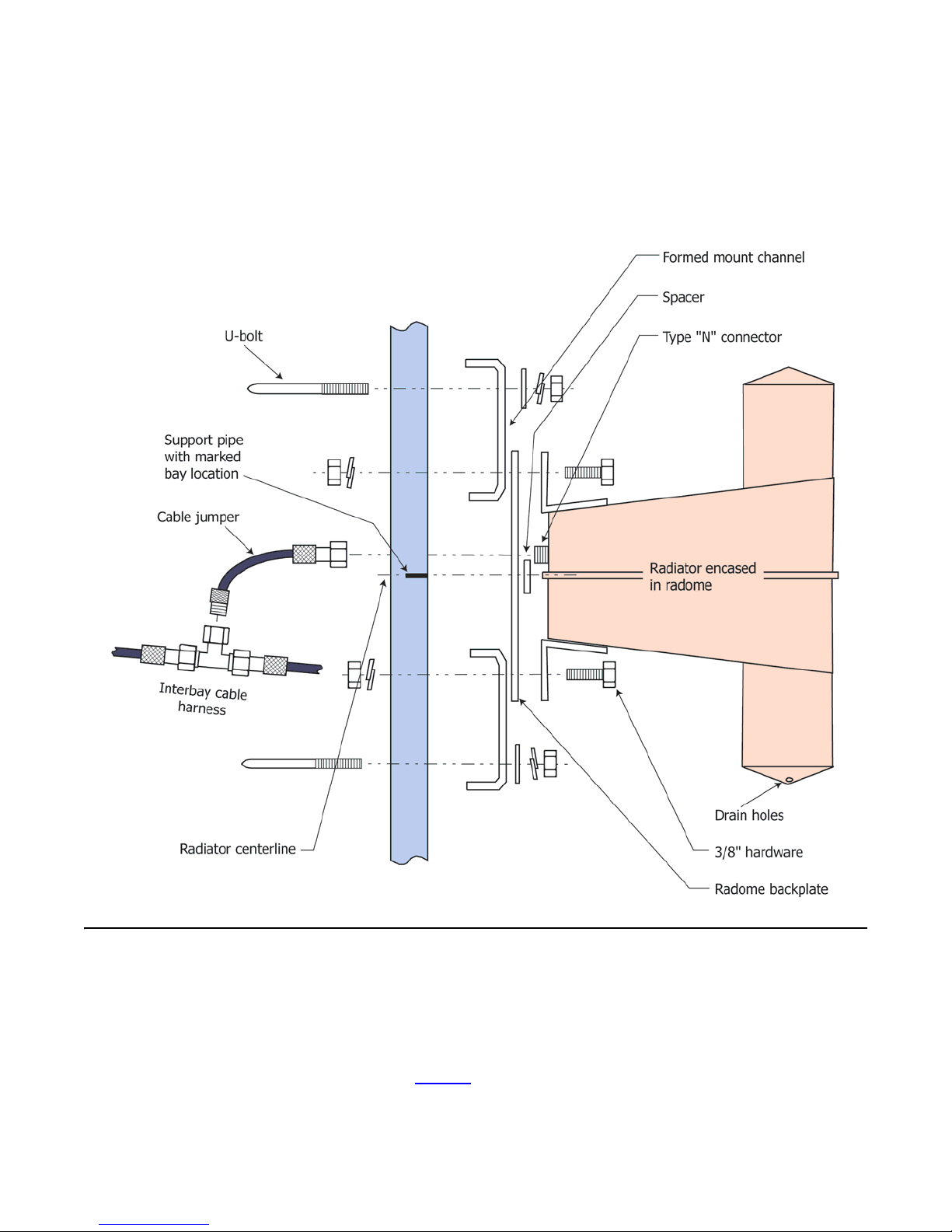
d. (Antennas with radomes) Using two U-bolts with nuts and washers, clamp
two formed mount channels, a backplate, a spacer, and the radiator/radome
assembly to the support pipe, as shown in Figure 5 on page 6.
e. Repeat for the remaining radiators, ensuring they are in the proper sequence
and oriented correctly per the installation drawing.
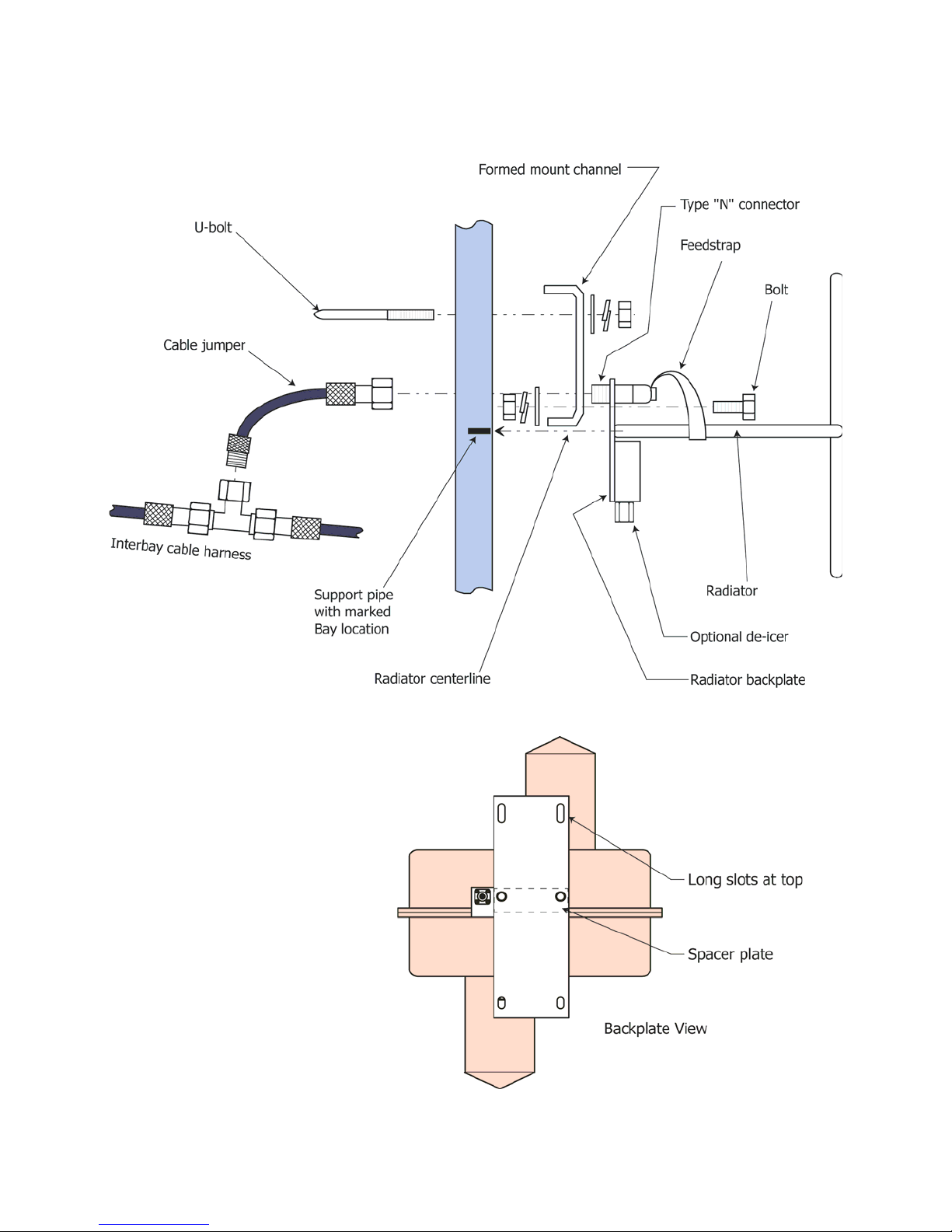
5
Antenna Installation
Figure 3. Installation of radiator
without radome, exploded view
Figure 4. Radome backplate
installation
Antenna Installation
6
f. Sight vertically along the installation to ensure the radiators are aligned
before finally securing them to the support pipe.
g. Touch up the paint on the support pipe as necessary to protect from
corrosion.
Figure 5. Installation of radiator
with radome, exploded view
Installing the interbay
cable harness
CAUTION
Tighten the connector nuts finger-tight only. Using pliers or other
mechanical means to tighten the connectors may damage them.
CAUTION
The minimum bend radius of RG-214 cable is 2 inches (50.8 mm).
a. Locate the end of the harness that is marked "Bay 1." Form the cable as
shown in Figure 6 and attach that end to radiator #1.

7
Antenna Installation
b. The rest of the interbay cable harness should naturally fall into place. Attach
the tees on the harness to the remaining radiators, as shown in Figure 3 or
Figure 5. For antennas with radomes, use the cable jumpers as shown.
c. Repeat step a for the bottommost connection.
The design of the antenna requires that the interbay feedline be about 50%
longer than the bay-to-bay spacing. To protect the slack cable from wind and
vibration damage, it must be wrapped and secured to the support pipe.
Figure 6. Installation of top and
bottom bays
CAUTION
To ensure proper antenna performance, the excess feedline must be
wrapped in a particular fashion, as shown in Figure 7 on page 8. DO
NOT make a continuous spiral wrap around the pipe, as shown on the
left. Doing so will ruin the VSWR of the antenna.
d. Wrap and secure the interbay feedline cable as follows (Figure 7):
CAUTION
Do not put too much tension on the feedline; just make it snug.
(1) Between each pair of antenna bays, loosen the connectors at both ends
just enough to allow the cable to swivel as it is wrapped. This will
prevent kinking.
(2) Grasp the feedline in the middle and pull it gently out like a bowstring.
(3) Then wrap the middle around the pipe, resulting in the “two-way spiral”
shown in Figure 7.
(4) Fasten the feedline to the pipe with plastic ties or electrical tape. Do not
use metal ties, which can cut the line.
(5) Retighten the connectors at both ends.
(6) Repeat for each interbay section.

Antenna Installation
8
Figure 7. Wrapping and securing
the interbay cables
CAUTION
If splicing tape is not applied correctly, water can get into the coax con-
nections and affect the performance and reliability of your antenna.
e. Apply splicing tape as follows (Figure 8 on page 9):
(1) Make sure the fittings and coax are clean and dry.
(2) Apply Scotch 130C Linerless Rubber Splicing Tape with the tacky side
up.
(3) Stretch tape and apply half-lapped to form a smooth, void-free splice.
Wrap tightly in and around the area where the connection is made.
Make sure the joint is fully covered, but do not seal up against the
bulkhead plate.
(4) Inspect the connection carefully, ensuring that the joint is fully sealed.
If more splicing tape is needed, simply add it to the existing wrap. It
adheres well to itself.
f. Stretch tape and apply half-lapped to form a smooth, void-free splice. Wrap
tightly in and around the area where the connection is made. Make sure the
joint is fully covered, but do not seal up against the bulkhead plate.
g. Inspect the connection carefully, ensuring that the joint is fully sealed. If
more splicing tape is needed, simply add it to the existing wrap. It adheres
well to itself.

9
Antenna Installation
Figure 8. Proper and improper
application of splicing tape
CAUTION
To prevent damage, secure all coax to minimize wind-induced motion
and chafing.
h. Tie all coax to the mounting pipe to prevent it from damage.


11
Installing the De-icer System (if applicable)
3 Installing the De-icer System (if applicable)
Precautions WARNING
Don't expose personnel to the medical hazards of intense radio fre-
quency (RF) radiation. Whenever working on the tower in the area of
the antenna, turn off all transmitters and lock them out so that they can-
not be turned on accidentally.
CAUTION
All parts of the de-icer system within approximately 20 feet (6 meters) of
any radiator must be shielded from RF energy, and the entire outdoor
portion of the system must be made waterproof.
CAUTION
An improperly installed de-icer can overheat and damage your antenna.
De-icer system
description
The de-icer system consists of the heating elements in the bays, their branch
cables, and the main harness. The main harness consists of a bay junction box
for each antenna bay, interbay cables, and a "pigtail" of wires about 10 feet (3
meters) long which you will connect to the tower junction box you are to pro-
vide. The following will help in installation:
• System electrical schematic: Figure 9 on page 12.
• Electrical specifications: Table 4 on page 13.
• Bay junction box: Figure 10 on page 14.
• Thermostat readings: Table 5 on page 15.
Your system may also include specially-ordered items, such as a ground-
mounted main control box, a power cable extending up the tower, or a tower-
mounted dual-setting thermostat.
Dual-setting thermostat CAUTION
Remember that conditions may be favorable for icing on the tower, even
if they are not on the ground.
Shively Labs deicers are designed to prevent ice from forming on antenna ele-
ments and are not designed to melt ice that has already formed. For this rea-
son, Shively Labs recommends that the system be installed with a tower-
mounted dual-setting thermostat assembly (Shively Labs Model 55522-G502)
and de-icer control box (Shively Labs Model 94068) that ensure the deicers
are operated in the temperature range ice is most likely to form.
Electric power The de-icer system requires 220 VAC, 50 - 60 Hz., single-phase. Table 4 shows
approximate heater leg resistances and current draw, respectively.
WARNING
Installation should be per-
formed only by personnel
experienced in RF sys-
tems, qualified in electri-
cal work, and familiar
with this equipment.
Installing the De-icer System (if applicable)
12
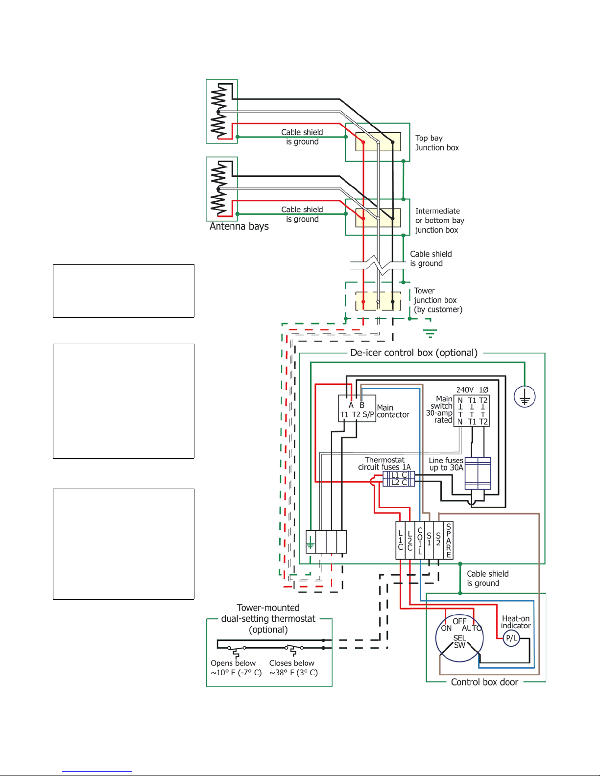
Figure 9. De-Icer electrical
schematic diagram
NOTE
Customer-supplied items
are shown in broken lines.
NOTE
A liquid-tight conduit con-
nector (3/8" conduit size
by 1/2" hub size) for the
harness entry to the
tower junction box, is
packed loose with the de-
icer harness.
NOTE
Shively recommends the
use of shielded braided
polyethylene-covered wire
or rubber-sheathed flexi-
ble metal conduit or rigid
conduit and weather-tight
fittings at all junctions.

13
Installing the De-icer System (if applicable)
De-icer installation
Installing the de-icer
harness
a. Install the main de-icer harness with its bay junction boxes as shown in
Figure 9 on page 12 and Figure 10 on page 14. Connect the leads from each
bay’s de-icer pigtail to the main harness in that bay’s junction box as shown.
CAUTION
It is important to ground both the tower junction box and the control
box, as shown in the schematic diagrams.
b. Furnish a tower junction box as shown schematically in 9 to connect the
antenna’s de-icer harness to the main power.
c. Using tie-wraps, secure the entire length of the de-icer harness to the RF
feedline at about 24" (60 cm) intervals. Run the ten-foot de-icer pigtail along
a feedline mount to the tower junction box and secure it to the mount and
the tower.
Table 4. De-Icer specifications
Heater Leg
Resistance,
Heater Leg
(T1 or T2)
Current Draw,
amps
1-Bay 203 0.6
2-Bay 101 1.2
3-Bay 68 1.8
4-Bay 51 2.4
5-Bay 41 3.0
6-Bay 34 3.6
7-Bay 29 4.1
8-Bay, single circuit 25 4.7
10-Bay, single circuit 20 5.9
12-Bay, single circuit 17 7.1
14-Bay, single circuit 14 8.3
16-Bay, single circuit 13 9.5
CAUTION
Shively Labs's de-icer
control box, Model 94068,
is designed for interior
installation only.
Installing the De-icer System (if applicable)
14
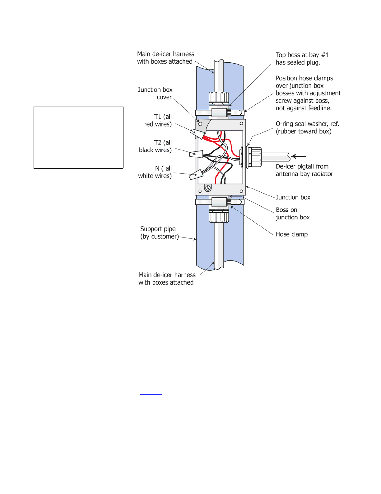
Figure 10. Bay junction box
installation
Installing the thermostat
(if applicable)
If you are using a thermostat, you may locate and mount it at your discretion.
We recommend mounting it as close as practical to the antenna.
CAUTION
When testing the thermostat, be sure to have one or both thermostat
leads disconnected before taking resistance readings. Otherwise, read-
ings may be affected by other components.
a. Before you connect the thermostat, measure the resistance across the
thermostat circuit and from it to ground to ensure that there are no short-
circuits. Thermostat readings should be as shown in Table 5 on page 15.
b. Mount the thermostat near the antenna and connect the thermostat leads to
points S1 and S2 in the control box as shown in the schematic diagram,
Figure 9 on page 12.
NOTE
Wire nuts, cover with
screws, and gaskets, and
tie-wraps are provided
with the de-icer cable
harness.
Table of contents
Other Shively Labs Antenna manuals

Shively Labs
Shively Labs 6020 Instruction Manual

Shively Labs
Shively Labs 6810 Operating and safety instructions

Shively Labs
Shively Labs Versa2une SLV User manual

Shively Labs
Shively Labs 6810 Owner's manual

Shively Labs
Shively Labs 6600 User manual

Shively Labs
Shively Labs 6017 User manual

Shively Labs
Shively Labs 6842 Owner's manual

Shively Labs
Shively Labs 6812DIN Owner's manual

Shively Labs
Shively Labs 6822 Owner's manual

Shively Labs
Shively Labs 6814 User manual


