Parsec Technologies ST. BERNARD A User manual

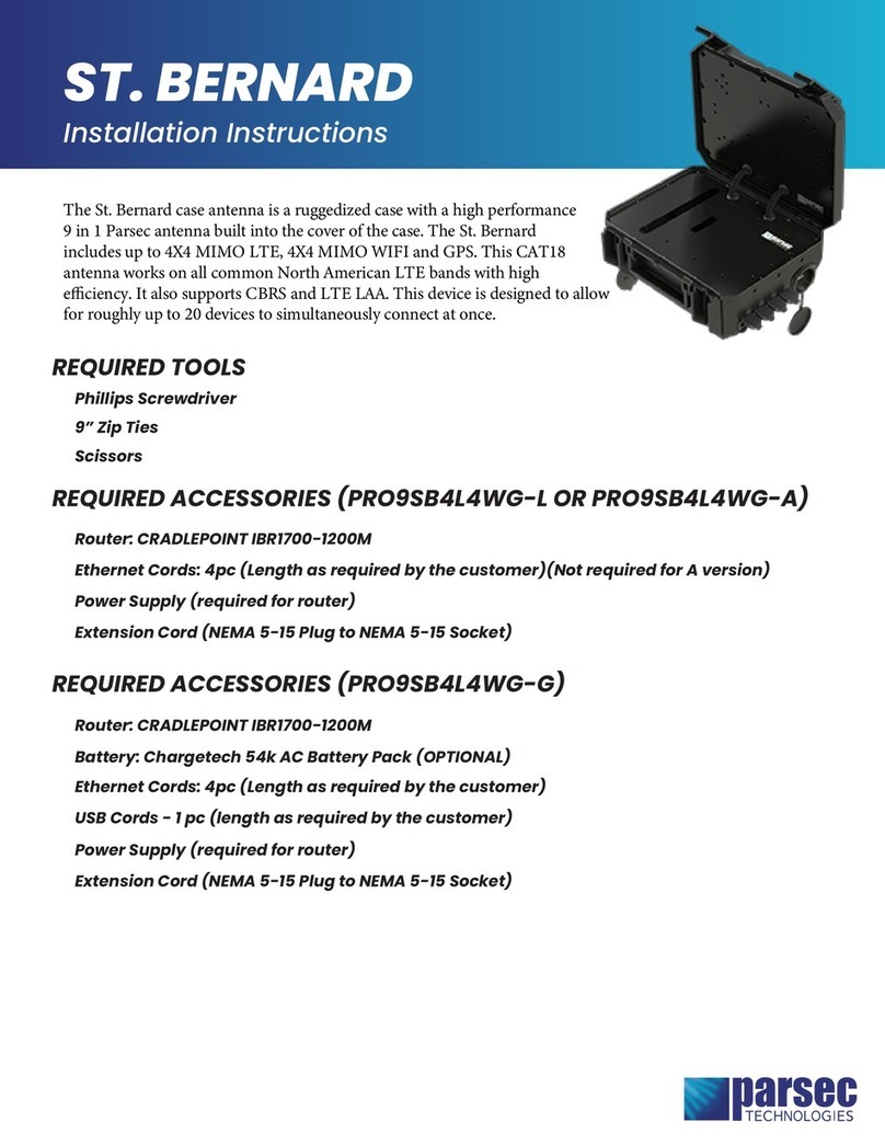
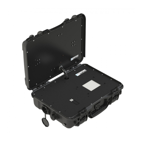
The St. Bernard case antenna is a high-performance Parsec antenna built into the cover of a protective
case. The St. Bernard case antenna is configurable up to nine-in-one with potential for 4X4 MIMO LTE, 4X4
MIMO WIFI, and GPS/GNSS. This 5G, IP67-rated* case antenna is designed for high performance during
adverse conditions and is portable in case of emergency.
Table of Contents
Antenna Versions ........................................................................................................................................................................................2
Required Tools & Accessories................................................................................................................................................................2
Battery and Router Installation.............................................................................................................................................................3
Connection .....................................................................................................................................................................................................6
Final Assembly............................................................................................................................................................................................. 11
Antenna Setup ............................................................................................................................................................................................ 15
Battery Operation and Safety Guidelines....................................................................................................................................... 18
ST. BERNARD
Installation Instructions
* Conditions apply

St. Bernard Installation Instructions Page 2 of 19
Antenna Versions
The St. Bernard case antenna comes in three versions –A, G, and L –with different features, listed below.
St. Bernard A
St. Bernard G
St. Bernard L
•AC Power Port
•4x RJ-45 Ports
•USB-A Port
•Battery Operated (battery not
included)
•40mm Fan
•AC Power Port
•4x RJ-45 Ports
•40mm Fan
Required Tools & Accessories
The following tools (not provided) are required in for the installation of the St. Bernard case antenna:
•Philips Screwdriver
•11/32” Wrench
The table below lists the required accessories for the A, G, and L versions of the St. Bernard case antenna.
St. Bernard A
St. Bernard G
St. Bernard L
Provided with Antenna
•PTA0071B Black Round Head
Screws, 14 pcs
•PTA0399-TL Pan Head Screws,
4 pcs
•NEMA Male to Female Adapter
•PTA0071B Black Round Head
Screws, 14 pcs
•PTA0368-B Black Flat Head
Machine Screws, 9 pcs
•PTA0399-TL Pan Head Screws,
4 pcs
•Ethernet Cords, 4 pcs *
•USB-A Cord *
•Battery Tray for ChargeTech
54K Battery Pack
•Cable Ties
•PTA0071B Black Round Head
Screws, 14 pcs
•PTA0399-TL Pan Head Screws,
4 pcs
•Ethernet Cords, 4 pcs *
•Cable Ties
To Be Purchased By
Customer
•Extension Cord (i.e. McMaster
#9581T22) ***
•54K AC Battery Pack
(ChargeTech #CT-600062)
•USB-A Cord **
•Ethernet Cords, 4 pcs **
•Extension Cord (i.e. McMaster
#9581T22) ***
•Cradlepoint IBR1700 (for other routers, contact customer service at support@parsec-t.com)
•12V 2x2 Router Power Supply (Cradlepoint #170716-000)
•Cable Ties (optional)
* For connecting the router to the ports on the case
** Optional for connecting external devices to the case, length as required by customer
*** For powering the antenna, length as required by customer, NEMA 5-15P outlet on case

St. Bernard Installation Instructions Page 3 of 19
Battery and Router Installation
Step 1: Mount the ChargeTech 54K battery pack to the cover plate (St. Bernard G only).
A. This step only applies to the St. Bernard G.
B. Remove the cover plate from the enclosure.
C. Remove the pads from the side of the battery pack, shown in Figure 1.
D. Insert the battery pack into the battery tray, as shown in Figure 2. Ensure that the battery pack
ports are at the open end of the battery tray.
E. Place the cover plate onto the battery tray and fasten with the nine PTA0368-B black flat head
machine screws provided in the kit, as shown in Figure 3. If the battery tray does not align
perfectly with the cover plate, partially tighten the screws at opposite diagonal positions first,
then install all other screws before fully tightening. It may help to install the screws in the
order shown in Figure 3.
Figure 1: Remove the pads from the side of the battery pack.
Figure 2: Place the ChargeTech battery pack into the battery tray. (St. Bernard G)
Battery Ports at
the Open End of
the Battery Tray

St. Bernard Installation Instructions Page 4 of 19
Figure 3: Fasten the battery tray with battery pack to the cover plate using PTA0368-B screws. (St.
Bernard G)
1
3
6
5
4
2
7
8
9

St. Bernard Installation Instructions Page 5 of 19
Step 2: Mount the router to the cover plate.
A. Align the router with the holes on the cover plate. Ensure the router orientation is correct. The
router display should be on the left side.
B. Mount the router using the four PTA0399-TL pan head screws provided in the kit, as shown in
Figure 4.
C. Guide the cable bundles back through the holes in the cover plate.
Figure 4: Fasten the router to the cover plate using PTA0399-TL screws.

St. Bernard Installation Instructions Page 6 of 19
Connection
Figure 5: Connection Diagram for St. Bernard A & L

St. Bernard Installation Instructions Page 7 of 19
Figure 6: Connection Diagram for St. Bernard G

St. Bernard Installation Instructions Page 8 of 19
Step 1: Connect the antenna cables to the router.
A. Use canned air or isopropyl alcohol to clean all the connectors to ensure that there is no dust in
the terminals.
B. Connect the antenna cables to the designated terminals on the router, as shown in the tables and
images below.
Cradlepoint IBR1700
Antenna Cable
Router Terminal
LTE 1
MAIN 0
LTE 2
AUX 0
LTE 3
MAIN 1
LTE 4
AUX 1
GPS
GPS
WIFI 1
2.4/5GHz, left
WIFI 2
2.4/5GHz, right
WIFI 3
5GHz, left
WIFI 4
5GHz, right
Figure 7: Cradlepoint IBR1700 Connections
WIFI 1
WIFI 4
WIFI 3
WIFI 2
Power
Supply
LAN
WAN
USB
LTE 3
LTE 4
LTE 1
LTE 2
GPS

St. Bernard Installation Instructions Page 9 of 19
Step 2: Connect the power supply to the router.
A. Connect the router power supply to the power supply port on the router, shown in Figure 7.
B. For St. Bernard A & L, plug the router power supply into the AC power port on the case.
C. For St. Bernard G, plug the router power supply into the NEMA male to female adapter. Plug the
NEMA male to female adapter into AC outlet on the battery pack, shown in Figure 8.
Step 3: Connect the fan to the router (St. Bernard G & L only).
A. This step only applies to the St. Bernard G and L.
B. Plug the USB-A cord from the fan into the USB-A port on the router, shown in Figure 7.
Step 4: Connect the router to the RJ-45 ports on the case using ethernet cords (St. Bernard G & L
only).
A. This step only applies to the St. Bernard G and L
B. Connect the provided ethernet cords to the LAN and WAN ports on the router, shown in Figure 7.
C. Connect the other ends of the ethernet cords from the router to the RJ-45 ports on the case. Keep
track of which cord is connected to the WAN port on the router. Consider connecting the WAN port
on the router to the front RJ-45 port and the LAN ports on the router to the back three RJ-45 ports,
as shown in Figure 8.
Figure 8: Connect the router to the RJ-45 ports on the case using ethernet cords.
WAN
LAN 2
LAN 3
LAN 1

St. Bernard Installation Instructions Page 10 of 19
Step 5: Connect the USB-A port on the case to the battery pack (St. Bernard G only).
A. This step only applies to the St. Bernard G.
B. Plug the provided USB-A cord into the USB-A port on the case and the USB-A port on the battery
pack, shown in Figure 9.
Step 6: Connect the battery pack to the DC charging port on the case (St. Bernard G only).
A. This step only applies to the St. Bernard G.
B. Connect the DC charging port cable from the case to the DC charging port on the side of the
battery pack, shown in Figure 9.
Figure 9: ChargeTech 54K Battery Pack Connections. (St. Bernard G)
AC Outlets
AC Output
Switch
DC Charging
Port
USB-A

St. Bernard Installation Instructions Page 11 of 19
Final Assembly
Step 1: Make sure all the cables and devices are properly connected.
A. Inspect every cable connection and ensure that no connections are loose.
B. Use cable ties or other wire management to neatly bundle the cables. Pack the cables neatly
inside the bottom half of the case. Ensure that the antenna cables are not excessively bent (1/2”
minimum bend radius). For the St. Bernard G, ensure that no antenna cables are running
across the top of the router.
Figure 10: Fully Connected 9in1 St. Bernard A with Cradlepoint IBR1700 Router

St. Bernard Installation Instructions Page 12 of 19
Figure 11: Fully Connected 9in1 St. Bernard G with Cradlepoint IBR1700 Router

St. Bernard Installation Instructions Page 13 of 19
Figure 12: Fully Connected 9in1 St. Bernard L with Cradlepoint IBR1700 Router

St. Bernard Installation Instructions Page 14 of 19
Step 2: Fasten the cover plate to the case.
A. Place the cover plate onto the bottom half of the case. Ensure that no cables are pinched
between the cover plate and the case.
B. Fasten the cover plate to the case using the fourteen PTA0071B black round head screws provided
in the kit, as shown in Figure 13.
Figure 13: Fasten the cover plate to the case using PTA0071B screws.

St. Bernard Installation Instructions Page 15 of 19
Operational Setup
Step 1: Open the fan and vent caps (St. Bernard G & L only).
A. This step only applies to the St. Bernard G and L.
B. Before turning the antenna ON, always open the fan and vent caps. The type of cap may vary.
C. Ensure that the antenna is away from any liquids when the caps are open.
Figure 14: Open the fan and vent caps. (St. Bernard G & L)
Step 2: Power on the antenna.
A. For St. Bernard A & L, connect a power cord to the AC outlet on the outside of the case.
B. For St. Bernard G, follow steps 2C-2G below.
C. Turn the battery pack ON by pressing and holding the power button for 3 seconds. The display on
the battery pack will indicate the battery pack’s current battery life (%). Do not hold the button for
longer than 3 seconds; this will cause the battery pack to enter programming mode. To exit
programming mode, turn the battery pack OFF then ON again.
D. Set the AC output switch on the battery pack to ON. The switch can be accessed through the slot
in the cover plate.
E. Shortly after turning on the battery pack, the fan will start.
F. To charge the battery pack, connect the battery pack charger to the DC charging port on the
outside of the case.
G. See Page 18 for Battery Operation and Safety Guidelines.

St. Bernard Installation Instructions Page 16 of 19
Step 3: Connect the antenna to a computer.
A. Use an ethernet cable to connect a computer to one of the RJ-45 ports on the case that are
connected to the LAN ports on the router.
Step 4: Login to Cradlepoint NetCloud.
A. Open a web browser on the computer and type 192.168.0.1 into the address bar. This will bring up
the Cradlepoint NetCloud login, shown in Figure 15.
B. Login to Cradlepoint NetCloud. The username is “admin”, and the password is found on the router,
shown in Figure 16.
Figure 15: Access Cradlepoint NetCloud.
Figure 16: Cradlepoint NetCloud Login Password

St. Bernard Installation Instructions Page 17 of 19
Step 5: Select the antenna in the device list on Cradlepoint NetCloud.
A. On the left side of the page, select STATUS. From the dropdown menu, select INTERNET and then
CONNECTIONS.
B. In the Device List table, select the option with a cellular SIM, as shown in Figure 17.
Figure 17: Select the device with a cellular SIM in Cradlepoint NetCloud.
Antenna setup is complete!
For best antenna performance, operate the antenna with the
lid closed and the case oriented with the lip on top.
If applicable, make sure the fan and vent caps are open while
using the antenna.

St. Bernard Installation Instructions Page 18 of 19
Battery Operation and Safety Guidelines
A. To manually power ON/OFF, press and hold the power button (located on the top of the unit) for 3
seconds. All LED lights/display should turn ON/OFF.
B. Holding the power button for longer than 3 seconds will cause the battery pack to enter
programming mode. To exit programming mode, turn the battery pack OFF and then ON again.
C. Recharging the battery pack can be done with the included 48W Charging Adapter or with a Type-
C PD Charger with at least 45W of power and up to 65W maximum.
D. To use the AC outlet, slide the AC power switch to the ON position and press the power button. The
solid red LED light will come on, which indicates that the AC outlet is on. A device plugged into the
AC outlet must be 15-250W for the AC outlet to work. Otherwise, the AC outlet will automatically
shut off.
E. If no power draw is detected after 90 seconds, the battery pack with shut OFF to conserve energy.
While the unit is OFF, press and hold the power button until the display begins flashing. This
activates continuous mode, and the entire unit will stay ON until manually turned OFF.
F. While plugged in and charging, the battery pack will allow pass-through charging to continue
powering any devices that are plugged in to the battery pack. To disable this function, press and
hold the power button for 2 seconds while the battery pack is charging. Repeat to re-enable pass-
through charging for all ports.
G. Warning: if the battery pack exceeds a safe operating temperature due to insufficient ventilation
or a high-temperature environment, the unit will automatically shut OFF.
H. Keep out of reach of children.
I. The product may become uncomfortable warm, reaching 140°F (60°C) under extended, high-
power usage. While using the product, make sure to keep it away from materials that may be
affected by high temperatures.
J. Hold on carefully when inserting or removing a cable. Make sure not to force or bend cables
when inserting them into the charging ports.
K. Avoid inserting any foreign objects into the ports.
L. Do not attempt to open, alter, or modify the unit.
M. Do not use in temperatures over 100°F (40°C).
N. Do not expose the product to wet conditions such as water, rain, or snow.
O. Failure to follow these safety guidelines may cause personal injury and/or property damage
to the product. It may also void the product warranty.

St. Bernard Installation Instructions Page 19 of 19
CAUTION
To comply with FOC RF Exposure requirements in section 1.1310 of the FCC Rules,
antennas used with this device must be installed to provide a separation distance of at
least 20 cm from all persons to satisfy RF exposure compliance.
DO NOT
•Operate the transmitter when someone is within 24 inches of the antenna
•Install the antenna or mast assembly on a windy day
•Install the mast close to power lines as it can cause serious injuries or death
WARNING
This document gives the detailed instructions to install an antenna to the best of our
knowledge. This document is for general information only. It cannot be used as a
warranty. Parsec Technologies Inc. will not accept any liability for any damage caused
by an antenna due to unknown variables.
Parsec Technologies
972-804-4600
support@parsec-t.com
Last Revised: 10-7-2022
This manual suits for next models
2
Table of contents
Other Parsec Technologies Antenna manuals
Parsec Technologies
Parsec Technologies Beagle G User manual

Parsec Technologies
Parsec Technologies K9 PRO Series User manual

Parsec Technologies
Parsec Technologies LABRADOR User manual
Parsec Technologies
Parsec Technologies GOLDEN RETRIEVER A User manual

Parsec Technologies
Parsec Technologies GREAT PYRENEES Series User manual

Parsec Technologies
Parsec Technologies ROTTWEILER User manual

Parsec Technologies
Parsec Technologies DOBERMAN User manual

Parsec Technologies
Parsec Technologies ST. BERNARD User manual
Parsec Technologies
Parsec Technologies NEWFOUNDLAND L User manual
Parsec Technologies
Parsec Technologies BELGIAN SHEPHERD User manual