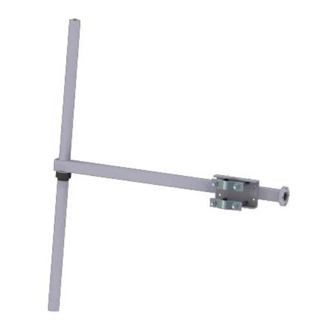
Shively Labs 6842 Owner's manual

Circularly Polarized FM
Broadcast Antenna
Model 6842
Instruction Manual
Installation, Operation, &
Maintenance

Congratulations! Thank you for purchasing one of the finest FM broadcast antennas on the
market today. The Shively Labs 6842 is the top-of-the-line in its class for its
simplicity, superior performance and durability.
Your purchase is backed by the best technical support in the industry. Shively
is a leading manufacturer in the broadcast industry, providing an extensive
range of antennas, transmission line and components. Our technical staff has
a wealth of experience in the broadcast industry and is standing by to serve
you in any way.
This manual is intended to give you a good basic understanding of your
antenna: its proper and safe installation, startup, and operation, and trouble-
shooting and maintenance information to keep it working satisfactorily for
years to come.
Please have everyone involved with the antenna read this
manual carefully, and keep it handy for future reference.
Meanwhile, please feel free to contact your sales representative at Shively
Labs at any time if you need information or help. Call or write:
Publication No. im-6842 (180423)

IMPORTANT
Please read this manual in its entirety before beginning
installation of your antenna!
Failure to follow the installation and operation
instructions in this manual could lead to failure of your
equipment and might even void your warranty!


i
Table of Contents Chapter 1 Preparation........................................................................ 1
Check the shipment............................................................................... 1
Torque specifications............................................................................. 1
Table 1 Torque specifications .......................................................... 1
Check the parts..................................................................................... 1
Set up the mounting pole. ..................................................................... 1
Figure 1 Tower layout, single-bay antenna ....................................... 3
Figure 2 Tower layout, two-bay antenna .......................................... 4
Figure 3 Tower layout, three-bay antenna........................................ 5
Figure 4 Tower layout, four-bay antenna.......................................... 6
Figure 5 Tower layout, five-bay antenna .......................................... 7
Figure 6 Tower layout, six-bay antenna............................................ 8
Figure 7 Tower layout, eight-bay antenna ........................................ 9
Figure 8 Top mounted installation.................................................. 10
Chapter 2 Bay Assembly...................................................................11
Attach the bay arms (antennas without
de-icers).......................................................................... 11
Figure 9 Attaching the arms .......................................................... 11
Attach the bay arms (antennas with de-icers). ...................................... 12
Attach the feedstrap............................................................................ 12
Figure 10 Attaching the feedstrap.................................................. 13
Chapter 3 Endseal Radome Installation...........................................15
Install the radome............................................................................... 15
Figure 11 Installing the endseal radome......................................... 15
Chapter 4 Mounting the Antenna Bay(s) .........................................17
Mount the antenna bays. ..................................................................... 17
Figure 12 Bay mounting on pole .................................................... 17
Chapter 5 Installing the De-icer System (if applicable)...................19
Precautions......................................................................................... 19
De-icer system description ................................................................... 19
Electric power ............................................................................... 19
Dual-setting thermostat ................................................................. 19
Figure 13 De-icer electrical schematic diagram ............................... 20
Table 2 De-icer specifications ....................................................... 21
De-icer installation .............................................................................. 21
Installing the de-icer harness ......................................................... 21
Installing the thermostat (if applicable)........................................... 21
Figure 14 Bay junction box installation ........................................... 22
Table 3 Thermostat readings......................................................... 23
Chapter 6 Connecting the Antenna (single-bay)..............................25
Connect the antenna bay..................................................................... 25
Figure 15 Single bay antenna connection ....................................... 25

ii
Table of Contents Chapter 7 Connecting the Antenna (2-bay) ..................................... 27
Mount the power divider...................................................................... 27
Connect the antenna cables. ................................................................ 27
Install the optional fine-matching transformer
(if applicable)................................................................... 27
Figure 16 Bay cable connection ..................................................... 28
Connect the tower transmission line. .................................................... 28
Figure 17 Two-way power divider, mounted and connected............. 29
Chapter 8 Connecting the Antenna (3-bay to 8-bay).......................31
Mount the power divider...................................................................... 31
Figure 18 Power divider, mounted and connected........................... 31
Install the optional fine-matching transformer (if applicable) .................. 32
Connect the antenna cables. ................................................................ 32
Figure 19 Bay cable connection ..................................................... 33
Connect the tower transmission line. .................................................... 33
Chapter 9 Startup............................................................................. 35
Before beginning initial characterization:............................................... 35
Read transmission line VSWR............................................................... 35
Read transmission line TDR. ................................................................ 35
Read system VSWR. ............................................................................ 35
Trim impedance. ................................................................................. 36
Figure 20 Impedance-matching transformer ................................... 36
Before beginning checkout: ................................................................. 37
Check out. .......................................................................................... 37
Operate.............................................................................................. 37
Figure 21 Apply the signal............................................................. 38
Chapter 10 Maintenance ..................................................................39
Log .................................................................................................... 39
Inspection .......................................................................................... 39
Paint .................................................................................................. 39
Return policy ...................................................................................... 39
Troubleshooting .................................................................................. 39
Broad spectrum RF noise. .............................................................. 39
High VSWR ................................................................................... 39
Change in coverage....................................................................... 39
Chapter 11 Parts ..............................................................................41
Bay components ................................................................................. 41
Table 4 Components, 6842 bay without de-icers (per antenna bay) 41
Table 5 Components, 6842 bay with de-icers (per antenna bay) ..... 41
Figure 22 Components, 6842 bay without endseal radome .............. 42
Table 6 Kit, endseal radome (per antenna bay) ............................. 42
Figure 23 Endseal radome components.......................................... 43
Feed system components .................................................................... 44
Table 7 Components, feed system for single-bay antenna ............. 44
Table 8 Components, feed system for 2-bay antenna .................... 44

iii
Table of Contents
Table 9 Components, feed system for 3-bay antenna ..................... 44
Table 10 Components, feed system for 4-bay antenna ................... 45
Table 11 Components, feed system for 5-bay antenna ................... 46
Table 12 Components, feed system for 6-bay antenna ................... 46
Table 13 Components, feed system for 8-bay antenna ................... 47
Accessories and optional items............................................................. 48
Table 14 Accessories and optional items for single-bay antenna ...... 48
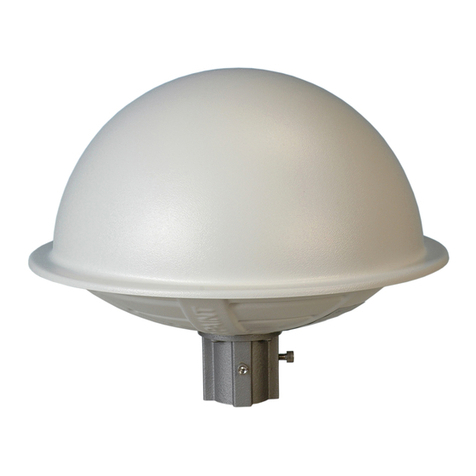
Table 15 Accessories and optional items for 2-bay antenna ............ 48
Table 16 Accessories and optional items for 3-bay antenna ............ 48
Table 17 Accessories and optional items for 4-bay antenna ............ 48
Table 18 Accessories and optional items for 5-bay antenna ............ 48
Table 19 Accessories and optional items for 6-bay antenna ............ 48
Table 20 Accessories and optional items for 8-bay antenna ............ 49
Appendix A Selected Assembly Drawings ........................................51
Figure 1 22° Feed Strap with Endseal Radome & Deicer .................. 52
Figure 2 6842 Exploded View with Endseal Radome........................ 53
Figure 3 Bay Arm Stickers ............................................................. 54
Figure 4 Power Divider Mount Detail .............................................. 55


1
Preparation
1Preparation
Check the shipment. As soon as you receive your antenna, BEFORE signing for the shipment:
a. Check to be sure all the material has arrived.
b. Check for evident damage to any of the boxes.
c. If any boxes are missing, or if any are obviously damaged, describe the
problem in a WRITTEN note on the shipping papers BEFORE signing them.
Then call Shively right away, and we’ll do everything we can to correct the
situation.
Important!
Never store the antenna system outdoors, boxed or otherwise. Take
pains to keep the antenna components dry. You will need to purge mois-
ture from the interior of the antenna components if they get wet.
Torque specifications. NOTE
Use an anti-seize compound to minimize galling on stainless steel
threads.
Check the parts. Check to be sure all the parts shown in Table 4 on page 41, Table 6 on
page 42, Table 8 on page 44, and Table 9 on page 44, as applicable, have
arrived in good condition.
NOTE
Item callouts are consistent across all the illustrations in this technical
sheet.
Set up the mounting
pole.
Remember!
It is YOUR responsibility to ensure that your installation meets all appli-
cable codes and the centerline-of-radiation requirements of your FCC
construction permit.
Table 1. Torque specifications
Hardware size Torque (dry) Torque (lubricated)
1/4-20 (radome flanges,
7/8" EIA flanges)
75.2 in-lbf (8.5 N-m) 63.9 in-lbf (7.2 N-m)
M6 stainless n/a 8.2 in-lb
5/16-18 (1-5/8" EIA flang-
es)
132 in-lbf (14.9 N-m) 112 in-lbf (12.7 N-m)
3/8-16 (2-1/8", 3-1/8" EIA
flanges)
236 in-lbf (26.7 N-m) 201 in-lbf (22.7 N-m)
1/2-13 galvanized steel
threaded rod (Grade 5)
94 ft-lb n/a
1/2-13 galvanized steel
bolt (Grade 2)
61 ft-lb n/a

Preparation
2
CAUTION
Before attaching the pole mounts to the tower, scrape away tower paint
to ensure good electrical contact. If you don’t, the antenna may gener-
ate unwanted electrical signals, and performance may be degraded.
a. Set up a outrigged round pole or pipe, 3" to 5-1/4" in diameter, 15" from the
tower face or leg. See Figure 1 through Figure 8, as applicable, for mounting
pole length requirements.
CAUTION
Watch for tower components that might interfere with your installation.
b. Mark the mounting pole at the locations where the antenna bays will be
mounted, in accordance with the installation drawing. The bay spacing is
critical.

3
Preparation
Figure 1. Tower layout, single-
bay antenna

Preparation
4
Figure 2. Tower layout, two-bay
antenna

5
Preparation
Figure 3. Tower layout, three-
bay antenna

Preparation
6
Figure 4. Tower layout, four-bay
antenna

7
Preparation
Figure 5. Tower layout, five-bay
antenna

Preparation
8
Figure 6. Tower layout, six-bay
antenna

9
Preparation
Figure 7. Tower layout, eight-bay
antenna

Preparation
10
Figure 8. Top mounted
installation

11
Bay Assembly
2 Bay Assembly
Attach the bay arms
(antennas without
de-icers).
[for single bay antennas and 1/2-wave-spaced antennas only]
a. Using 1/4-20 x 1-3/4" hardware (Figure 9a, 2, 3, and 4), attach the four
antenna arms (5) to the
innermost
pair of holes on the boom (1) mounting
stubs.
[for 2- to 8-bay full-wave-spaced antennas only]
b. Using 1/4-20 x 1-3/4" hardware (Figure 9b, 2, 3, and 4), attach the four
antenna arms (5) to the
outermost
pair of holes on the boom (1) mounting
stubs.
c. Tighten the hardware before continuing.
Figure 9. Attaching the arms

Bay Assembly
12
Attach the bay arms
(antennas with de-
icers).
The bay de-icer pigtail is shipped pre-assembled. Handle the de-icer compo-
nents carefully to prevent damaging them when assembling the bay.
CAUTION
When installing the screws securing the arms to the stubs (Figure 9c),
be very careful not to damage the bay de-icer heater (15) and pigtail
(16) within.
[for single bay antennas and 1/2-wave-spaced antennas only]
a. Using 1/4-20 x 1-3/4" hardware (Figure 9a, 2, 3, and 4), attach the four
antenna arms (5) to the
innermost
pair of holes on the boom (1) mounting
stubs.
[for 2- to 8-bay full-wave-spaced antennas only]
b. Using 1/4-20 x 1-3/4" hardware (Figure 9b, 2, 3, and 4), attach the four
antenna arms (5) to the
outermost
pair of holes on the boom (1) mounting
stubs.
c. Tighten the hardware before continuing.
Attach the feedstrap. a. If necessary, remove the bolt and washers (Figure 10, 6, 4, and 7) from the
center of the endseal (the white plastic dome on the antenna mast).
b. Using the endseal hardware you removed above, attach the center hole of
the feedstrap (8) to the endseal, but do not tighten it fully yet.
c. Using the 1/4-20 x 1-3/4" hardware (2, 3, and 4), attach the feedstrap ends
to the inside of the antenna arms as shown. Tighten to 7 ft-lb.
NOTE
The feedstrap should cross the antenna mast at an angle of approxi-
mately 22° from perpendicular, as shown.
Important!
Do NOT twist the feedstrap with the endseal nut tightened. You may
damage internal components.
d. For antennas without radomes, grasp the flat sections near the center of the
feedstrap, and twist it in a flat plane until the center section rests (the ends
of the feedstrap will twist, as shown in Figure 10 - and it will spring back
somewhat) crossing the antenna mast at a 84° - 90° angle.
CAUTION
Tighten the endseal hardware only until the lock washer flattens. Do not
overtighten.
e. Tighten the endseal hardware.
Table of contents
Other Shively Labs Antenna manuals

Shively Labs
Shively Labs 6020 Instruction Manual

Shively Labs
Shively Labs 6600 User manual

Shively Labs
Shively Labs Versa2une SLV User manual

Shively Labs
Shively Labs 6812B Owner's manual

Shively Labs
Shively Labs 6812DIN Owner's manual

Shively Labs
Shively Labs 6017 User manual

Shively Labs
Shively Labs 6814 User manual

Shively Labs
Shively Labs 6822 Owner's manual

Shively Labs
Shively Labs 6810 Owner's manual

Shively Labs
Shively Labs 6810 Operating and safety instructions