shockrite SRB20 User manual

1

Contents
1. Introduction..........................................................................1
2. Safety Requirements and Regulations................................1
3. Specification........................................................................3
4. Installation Guide.................................................................4
5. Troubles ooting...................................................................5
6. Guarantee...........................................................................5
7. Contact Information.............................................................6
2

1. INTRODUCTION
Thank you for buying a ShockRite electric fence energiser. This energiser has built-in lightning
protection devices to reduce the risk of lightning damage, and has built-in RFI (Radio Fre uency
Interference) suppressed circuitry. If for any reason you are not happy with your purchase, please
return the energiser to your dealer within 30 days of purchase and we will give you a full refund.
Please read this manual carefully before installation.
This manual refers to ShockRite electric fence energisers SRB20, SRB60, and SRB120.
2. SAFETY REQUIREMENTS AND REGULATIONS
WARNING: Please read the following installation requirements and regulations:
Ensure energiser is turned off before touching fence.
Do not submerge energiser in water or expose to possible flooding.
Keep battery in a well ventilated area.
For animal use only, warning signs must be displayed.
Make sure energiser is well earthed in continuous damp soil.
Poor earthing, insulation or excessive vegetation will reduce the effectiveness of the
energiser.
Do NOT climb over, through or under a multi -wire electric fence, use a gate or a specially
designed crossing point.
Avoid electric fence configurations that are likely to lead to the entanglement of animals or
people.
Electric fences should be installed and operated so that they cause no electrical hazard to
persons, animals or their surroundings.
Children or infirmed persons must be supervised at all times.
Do not place combustible materials near the fence or energiser connections. In the event of
a fire, the energiser must be disconnected.
Do not dismantle or attempt to make any changes to the energiser yourself.
Do not supply an electric fence from two separate energisers or from independent fence
circuits of the same energiser.
Only one energiser at a time can be connected to any fence.
The minimum distance allowed between two separate electric fences powered by their own
energiser is 2.5m, should these fences need to be connected this can only be done using
non conductive material.
Do not electrify barbed or razor wire.
In areas of public access, use an electric fence warning sign every 10m (33ft) to identify the
electrified wire(s).
Crossing with overhead power lines should be avoided wherever possible. If such a crossing
cannot be avoided, it should be made underneath the power line and at right angles.
If connecting leads and electric fence wires are installed near an overhead power line, the
3
clearances should be not less than those shown below:
Power Line Voltage
(Voltage)
Clearance
(Metres)
Under 1,000
Between 1,000 and 33,000
Over 33,000
3
4
8
If connecting leads and electric fence wires are installed near an overhead power line, their
height above the ground should not exceed 3m.
This height applies either side of the orthogonal projection of the outermost conductors of
the power line on the ground surface, for a distance of:
• 2 metres for power lines operating at a nominal voltage not exceeding 1,000 volts;
• 15 metres for power lines operating at a nominal voltage exceeding 1,000 volts.
Electric animal fences intended for deterring birds, household pet containment or training
animals such as cows need only be supplied from low output energisers to obtain
satisfactory and safe performance.
For electric animal fences intended for deterring birds from roosting on buildings, no electric
fence wire should be connected to the energiser earth electrode. A warning sign should be
fitted to every point where persons may gain ready access to the conductors.
Fence wiring should be installed well away from any telephone line, telegraph line or radio
aerial.
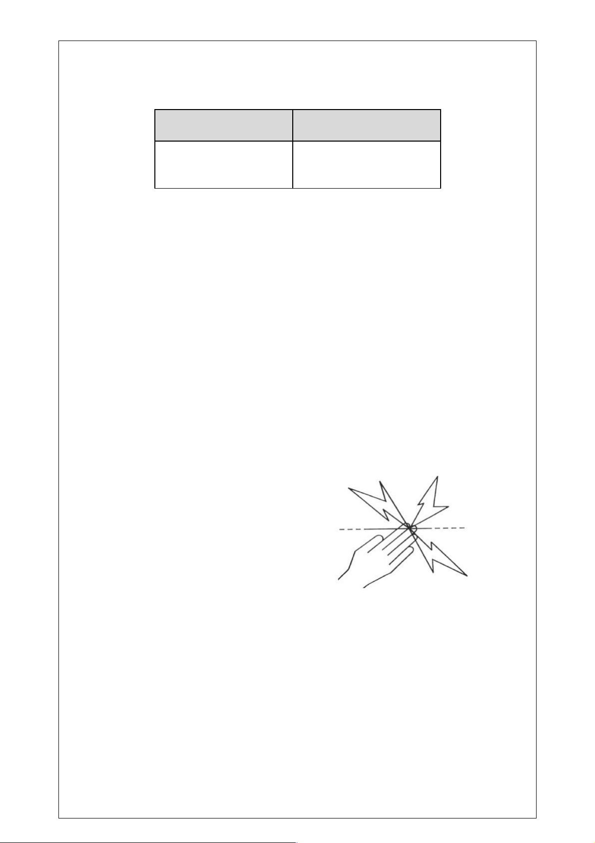
The size of the warning sign must be at least 100mm x 200mm.
The background colour of both sides of the warning sign should be yellow. The text on the
sign should be black and should show either:
- “CAUTION: Electric Animal Fence” or,
- The symbol shown:
The inscription must be indelible, inscribed on both sides of the warning sign and have a
height of at least 25mm.
This energiser complies with international safety regulations and is manufactured to international
standards.
4

3. SPECIFICATION
Key
1. Pulse/ Low Battery Indicator
2. Earth Terminal
3. Fence Terminal
4. Battery Connection Cable
5. On/Off Switch
6. Earth Stake
7. Wing Bolt
Contents:
1 x Battery operated Energiser 1 x Fence Wire
1 x Earth Wire 1 x Earth Stake/Mount & Wing Bolt
eatures:
1. Weatherproof heavy duty case 2. Low average current use
3. On/Off Switch 4. Pulse Indicator
5. CE, ROHS approved 6. Low battery Indicator
7. Easy-access terminals, and mounting brackets
for uick connection and installation
Weight: 1.0kg.
Size: 175mm x 135mm x 60mm
Ingress Protection Rating: IP44
5

Characteristics:
Model
Number
Output
Energy
(Joules)
Stored
Energy
(Joules)
Power
Source
Open
Volts
Power
Consumption
500 Ohm
Load
Volts
Power
Length
(km)
SRB20 0.2 0.25 12V 8,500 25mA 4,500 3
SRB60 0.6 0.7 12V 10,000 60mA 4,500 10
SRB120 1.2 1.3 12V 10,000 120mA 5,600 20
**Distance is based on single strand high tensile galvanized wire (no vegetation)
4. INSTALLATION GUIDE
(Image for illustration purposes only)
Step1. Mounting the energiser
Connect the two sections of the earth stake together using the wing bolt provided, and insert the
earth stake into moist soil.
Ensure the energiser is correctly mounted onto the earth stake by its mounting point to prevent
water damage.
Step 2. Earthing the Energiser
Place the earth stake in continuously damp soil. Using the earth connection cable provided
attach the cable to the earth terminal of the energiser and then attach the crocodile clip to the
earth stake (which the energiser is mounted on).
Step 3. Connecting Energiser to fence
Connect the energiser’s live terminal to the fence using the red connection cable provided.
6
Step 4: Connecting to Power Supply
Connect the red crocodile clip to the “+” on the battery and the black crocodile clip to the “-” on
the battery. Recommended battery for energiser operation is a 85 Ah 12 volt Leisure battery.
(Battery Not Included )
Step 5. Operation
Under normal operation the LED on the unit will flash green once every 1.5 seconds, if the
battery voltage drops to 11.6 volts or less the led on the energiser will flash red and at a slower
pace (every 2.5 seconds) to conserve power.
5. TROU LESHOOTING
Warning: Do not dismantle the unit to repair. Please contact your supplier.
Fault Solution
The Pulse
indicator light
is flashing, but
the electric
shock delivered
by the fence is
weak
Check that all connections in the fence and earth system are firm and
secure. If necessary, clean away any corrosion.
Check that the earth stake is pushed firmly into good conduction soil
Check for faults in the fence-line caused by trees or vegetation. If
necessary, remove obstructions and mend the fence.
Check that the energiser is ade uate for the length of the fence. If
necessary, reduce the length of the fence or reduce the number of fence
wires. Alternatively, divide the fence-line into smaller zones, with each
zone powered by a separate energiser.
The Pulse
indicator light
is not flashing
Check that the energiser is switched on
Check the battery is fully charged
Check that the red lead is connected to the (+) terminal of battery,
black lead to (-) terminal
6. GUARANTEE
We offer a 3 Year Warranty starting from the date of the purchase. We will only perform
warranty services when the unit is returned to us un-tampered. If these re uirements are not
fulfilled, we reserve the right to void warranty.
7

7. CONTACT INFORMATION
If you have any further technical uestions about our products, please contact us:
McGrath Supplies Ltd - ShockRite
72 Derrybrick Road
Carrickoughter
Kesh
Northern Ireland
BT93 1BL
Tel: 028 686 31323
E-mail: [email protected]
Website: www.shockrite.co.uk
8
This manual suits for next models
2
Table of contents
Other shockrite Camera Accessories manuals


