SHOKO SCIENTIFIC Shodex CD-200 User manual

121056
READ
this operation manual
CAREFULLY
before using
Shodex® CD-200 Electric Conductivity Detector.
Electric Conductivity Detecto
r
Operation Manual
®CD-200

Copyright C 2011-2012, SHOKO SCIENTIFIC CO.,LTD. Printed in Japan.
All rights reserved. Contents of this publication may not be reproduced in any form or by
any means (including electronic storage and retrieval or translation into a foreign language)
without prior agreement and written consent from the copyright owner.

Notice
Users of Shodex®
CD-200
Electric Conductivity Detector (hereinafter Shodex
CD-200
) are requested to use it in strict accordance with the instructions in this manual.
Nothing contained in this manual shall be construed as giving any guarantee on
Shodex
CD-200
or granting or implying any license or immunity under any patent
or other rights.
Shodex
CD-200
must be used on the user's own responsibility and in strict
compliance with all applicable laws and regulations.
The information contained in this operation manual was obtained from sources
that we believe are reliable, but no warranty or representation is hereby given
as to its accuracy or completeness.
This operation manual does not expect Shodex
CD-200
to be used for clinical or
medical purposes. Shodex
CD-200
must not be used for such purposes.
The content of this operation manual is subject to change without notice.
Notice that the parts supply period for this product is 7 years from the end of
production. Please be aware that replacement parts may not be available beyond the
parts supply period.
Warranty
Except for a written warranty signed by its duly authorized representative and
specifically issued, SHOKO SCIENTIFIC CO.,LTD. makes no warranty,
express or implied,
written or oral, statutory or otherwise, as to the quality, performance,
workmanship,
fitness for a particular purpose, or merchantability of Shodex
CD-200
.
Precautions
Thank you for your continued patronage. Observe the following precautions
in order to make safe and stable use of the detector.
Precautions are divided into three groups in this operation manual,
depending on the degree of danger. The three groups are
: This sign is used where failure to follow strictly the instructions
and procedures indicated by this sign may cause injury or
damage to health.
: This sign is used where failure to follow strictly the instructions
and procedures indicated by this sign may cause this detector
and the peripheral apparatus to deteriorate or break down.
: This sign is used wherever information is given to ensure optimal
performance of the detector.
Precautions listed below are those of particular importance extracted
from
this operation manual :
Do not use the detector in places where combustible gas or any
source of fire or spark exists or might exist.
Prior to connection, make sure that the voltage of the power
socket into which the detector power cable is plugged is the
same as the power supply voltage indicated on the detector.
The power socket into which the detector power cable is
plugged should be of a 3P type with a grounding terminal.
Other types of power sockets should not be used.
When using organic solvent, wear safety goggles.
It is recommended that a sink or equipment for washing the eyes
be installed nearby in case the organic solvent in use comes into
contact with the eye(s) or skin.
When any abnormality, such as liquid leakage, is observed, immediately
turn off the power and unplug the detector from the main power
source.
!
Warning
Caution
Note
!
Warning
!
Warning
!
Warning
!
Warning
[ Important
! ]
!
Warning

Do not use the detector with the cover open; always unplug the
detector from the main power source before opening the cover.
If the detector is used in a manner not specified by this operation
manual, the protection provided by the detector may be impaired.
When using flammable organic solvent as mobile phase, be sure
to make necessary arrangement to prevent accidental ignition
(fire) by static electricity.
If the fuse blows after being replaced, power off the detector
immediately and disconnect the power cord. Please consult
our local representative in your area or SHOKO SCIENTIFIC.
As this detector is readily affected by the ambient temperature, use
it in places where there is little wind or change in the ambient
temperature. Do not use the detector near any source of vibration,
electrical noise, or in places where corrosive gas and a lot of dust
are present.
External input/output terminals are for contact closure.
Never apply voltage to them.
Do not connect any tube other than the provided "OUT tube"
to the eluent outlet joint of the detector. Put the exit end of
the "OUT tube" in the waste liquid bottle and do not apply back
pressure.
When connecting this detector to other detectors in series, put
it at the end.
Make sure that no back pressure is applied to the outlet of the
detector. Connect the tip of the Teflon tube on the cell outlet of the
detector to a receptacle for waste liquid.
If eluent freezes inside the detector, the flow line might break,
damaging the detector. If there is any chance of eluent freezing
during stoppage or storage of the detector, withdraw the eluent
completely from the flow line of the detector.
When using any eluent containing a salt at high concentration, make
sure that the flow line is washed with water thoroughly after use
.
Failure to do so may result in plugging of the line, causing the
detector to cease operation.
If the detector is not to be used for more than one week, prior
to storage, wash the flow line with pure water or acetone, and dry
the line by allowing nitrogen gas to flow through it.
Do not use any eluent which might corrode the material, such as
stainless steel, that it comes into contact with. Use of such eluent
might cause a base line drift and damage the detector.
Caution
Caution
Caution
Caution
Caution
Caution
Caution
Caution
!
Warning
!
Warning
!
Warning
!
Warning
Caution

Use a thoroughly degassed eluent. It is recommended that a degassing
device be used to degas the eluent, as it is easy to use and permits
continuous degassing.
If an eluent is replaced with another eluent, replace all channels of the ion
chromatograph with new eluent. When eluent replacement is not sufficient,
it may become the cause of an unstabilized baseline.
When high voltage caused by static electricity is applied to the instrument,
some incorrect actions may be observed. Please take note of static
electricity.
Please do not set other equipment on this detector, in order to avoid
enlarging the baseline drift and losing control of the temperature.
Note
Note
Note
Note

Contents
1 . Accessories ・・・・・・・・・・・・・・・・・・・・・・・・・・・・・・・・・・・・・ 1
2 . Features ・・・・・・・・・・・・・・・・・・・・・・・・・・・・・・・・・・・・・・ 2
3 . Specifications ・・・・・・・・・・・・・・・・・・・・・・・・・・・・・・・・・・・ 3
4 . Measuring mechanism ・・・・・・・・・・・・・・・・・・・・・・・・・・・・・ 4
4-1 Detecting System ・・・・・・・・・・・・・・・・・・・・・・ 4
4-2 Electric System ・・・・・・・・・・・・・・・・・・・・・・ 5
5 . Nomenclature and Functions ・・・・・・・・・・・・・・・・・・・・・・ 6
5-1 Front Panel ・・・・・・・・・・・・・・・・・・・・・・・・・・ 6
5-2 Side Panel ・・・・・・・・・・・・・・・・・・・・・・・・・・・・・ 7
5-3 Back Panel ・・・・・・・・・・・・・・・・・・・・・・・・・・・・・ 8
5-4 Display ・・・・・・・・・・・・・・・・・・・・・・・・・・・・・・・・・・ 10
6 . Installation and Connections ・・・・・・・・・・・・・・・・・・・・・・ 13
6-1 Power Connection and Grounding ・・・・・・・ 13
6-2 Signal cable Connections ・・・・・・・・・・・・・・・・ 14
6-3 Tube Connections ・・・・・・・・・・・・・・・・・・・・・・ 15
6-4 Operation Procedures ・・・・・・・・・・・・・・・・・・・・ 16
7 . Maintenance ・・・・・・・・・・・・・・・・・・・・・・・・・・・・・・・・・・・・・ 18
7-1 Flow Line Cleaning ・・・・・・・・・・・・・・・・・・・・・・ 18
7-2 Replacing Fuse ・・・・・・・・・・・・・・・・・・・・・・・・ 18
7-3 Cleaning of detector
exterior ・・・・・・・・・・・・・ 18
8 . Troubleshooting ・・・・・・・・・・・・・・・・・・・・・・・・・・・・・・・ 19
9 . WEEE Instructions ・・・・・・・・・・・・・・・・・・・・・・・・・・・・・ 20
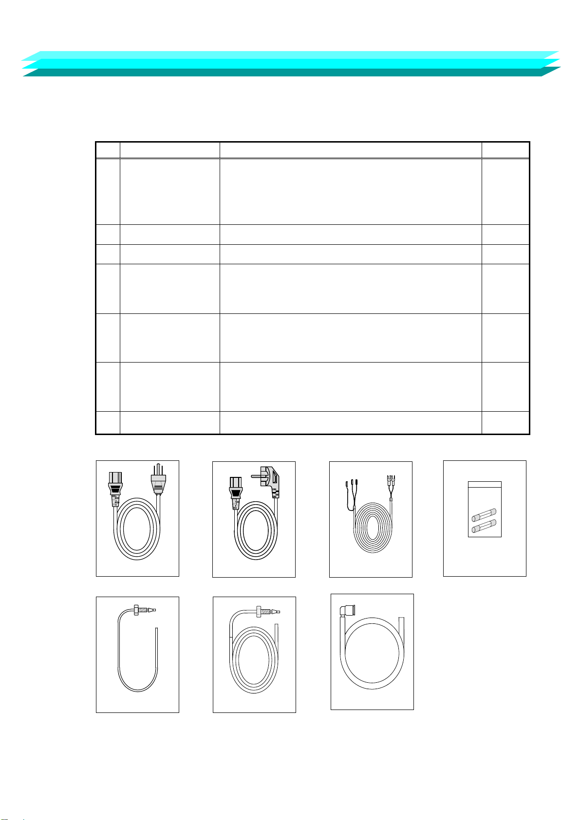
1. Standard accessories
When unpacking, please verify that all the following accessories are included:
【 Details of Accessories 】
No. Name Specification Quantity
1 Power cable
3-core cord with a grounding electrode (100V)
(1) For voltage of 100 or 120 VAC
Power supply cable set (125 V)
(2) For voltage of 220 or 240 VAC
Power supply cable set (250 V)
1*
2 Signal cable 2-core shield cable (approx. 2 m) 1
3 Fuse Time-lag type 500 mA (T500 mA L/250 V)
4 IN tube set
Teflon tube of 1.6 mm outer dia. x 0.25 mm inner dia.
x 1000 mm length
(PEEK setscrew with ferrule attached)
1
5 OUT tube set
Teflon tube of 2.5 mm outer dia. x 1.5 mm inner dia.
x 2000 mm length
(connecting tube, setscrew, and ferrule attached)
1
6 Discharge
tube set
Silicone rubber tube of 10 mm outer dia. x 7 mm
inner dia. x 2000 mm length
(connection joint attached)
1
7 Operation manual 1
*: Either 1-(1) or 1-(2) is attached according to the power supply voltage at the first destination.
When unpacking, please verify that all the following accessories are included:
- 1 -
1-(1) 1-(2)
4
3
5
2
6

2. Features
Shodex CD-200 is an Electric Conductivity Detector for HPLC and has the following features:
1) Stability
The double temperature control system provides for a very fast start up time
and excellent stable baseline performance.
2) Safety
Solvent leak sensor generates an output signal that stops pump flow in case of
an eluent leak within the detector.
3) Integration
Well-organized Output signal terminals and USB communication port guarantee
high-level integration and automation in conjunction with your HPLC system.
- 2 -

3. Specifications
1) Measuring method : Two-electrode system
2) Measuring limits : 0-600 mS/m
3) Measuring range : 0.0025-5.12/0.025-51.2/0.25-512 mS/m (12 steps)
4) Linearity range : 0-600 mS/m
5)
Noise
:
< 0.0005 mS/m (response; 1 sec) or less
(2.5 mM phthalic acid ; pH 4.0 ; 1.5 ml/min.)
6) Response : 0.1, 0.25, 0.5, 1.0, 1.5, 2, 3, 6 seconds
7) Zero adjustment : Automatic zeroing
8) Base line shift : Limit; 0-2 mS/m, Resolution; 0.01mS/m
9) Integrator output : 0-1 V (Sensitivity; 2/20/200 mV/mS/m)
10) Recorder output : 0-10 mV (for each range)
11) External contact input : ZERO IN/MARKER IN
12)
External contact output
:
・READY (Temperature control stabilized)/LEAK/
・ERROR (ROM/RAM/PARAMETER/LEAKAGE/ SENSOR
ERROR/OVER HEAT/ZERO OVER/ COMUNICATION)/
・MARKER OUT
(Contact capacity : 24 VDC, 0.1 A )
13)
Temperature control
:
OFF, 30-50℃ in increments of 1℃ (with a 77℃ thermal
fuse)
(Note) External cylinder is adjusted to a temperature
that is 5℃ lower than setting temperature.
14) External communication : USB
15) Cell volume : approx. 2.5 μl
16) Pressure rating : 1 MPa
17) Wetted part material SUS316, PTFE, PEEK
18)
Dead volume
:
Inlet → Cell ; approx. 75 μl
Cell → Outlet ; approx. 25 μl
Total dead volume ; approx. 103 μl
19) Power supply : 100-240 VAC ± 10% , 50/60 Hz
20) Demand : approx. 50 VA
21) Outside dimensions : approx. 260W x 400D x 150H mm (excluding rubber footing)
22) Weight : 8 kg
- 3 -
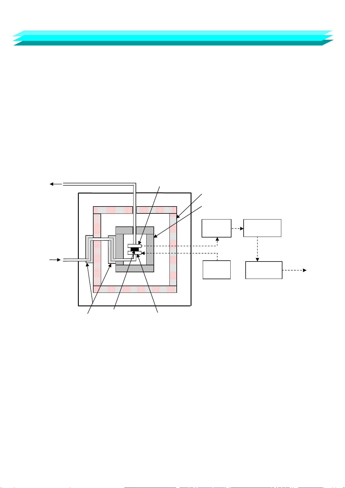
(OUT)
ElectrodeⅠ
Electrode Ⅱ
Heat exchangers
Internal cylinder (adjusted to the
setting temperature)
External cylinder (adjusted to the
temperature of 5°C lower than the
setting temperature)
AC
oscillator
I/V
converter
Synchronous
rectifier
Conductivity
signal
Signal
processor
Eluent
IN
Spacer
4. Measuring mechanism
4-1 Detecting system
This detector has adopted a two-electrode system, and the detection cell and flow line are as shown
in Fig. 4-1.
In Fig. 4-1, a current proportional to the electrical conductivity of eluent is output from electrode I
when an ac voltage is applied to electrode II. This current signal is output as the electrical
conductivity signal through an I/V converter, a synchronous rectifier, and a signal processing circuit.
In addition, the temperature dependence of eluent is large, and in order for the electric conductivity
of eluent to minimize this effect, the detection cell is contained in an inner cylinder which is adjusted
to the setting temperature, and the inner cylinder is contained in an outer cylinder which is adjusted
to a temperature that is 5℃ lower than the setting temperature.
In addition, two heat exchangers are prepared in the inner cylinder and the outer cylinder,
respectively, so that the temperature of eluent may attain the setting temperature.
Fig. 4-1 Measuring system
- 4 -
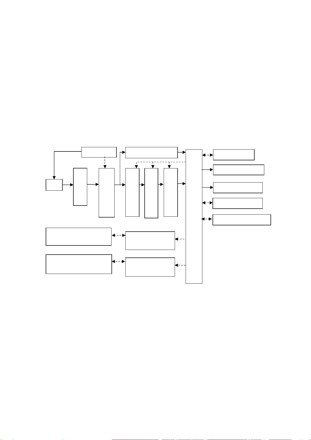
Cell
I/V converter
Synchronous rectifier
AC oscillator A/D converter for display
Coarse zero circuit
Sensitivit
y
settin
g
circuit
Precision A/D converter
Digital signal processing circuit
Display/keyboard
Integrator output circuit
Recorder output circuit
Communication port
External input/output circuit
Internal cylinder temperature
sensor/heater
External cylinder temperature
sensor/heater
Internal cylinder
Temperature controller
External cylinder
Temperature controller
4-2 Electric system
The electric system of Shodex CD-200 consists of an oscillator (generating AC voltage),
a signal processing circuit, a display/keyboard circuit, and two temperature control circuits.
Fig 4-2 shows a block diagram of the electric system.
The oscillator applies AC voltage to the cell, generating an electric AC current proportional to
the electrical conductivity of the eluent, in the cell electrode. The current is converted into
a voltage signal by the I/V converter. Then the voltage signals are converted by the synchronous
rectifier into DC voltage signals which depend on electrical conductivity of the eluent.
This DC voltage signal is displayed as electrical conductivity of eluent, and converted to a precision
digital signal after passing through the coarse zeroing circuit and the integrator range setting circuit.
This precision digital signal is transferred to the digital signal processing circuit.
This precision digital signal is processed for response setting, automatic zeroing, polarity setting,
base line shift, marker summation, and output for Integrator output, recorder output, and
communication port output as a differential electrical conductivity voltage signal.
The temperature control circuit for the internal cylinder is kept at a private temperature, and the
temperature control circuit for external cylinder is kept at a temperature which is 5 degrees
lower than private temperature.
Fig. 4-2 Electrical System
- 5 -
5. Names and functions of parts
5-1 Front Panel
□
2 □
3
□
4
□
5
□
6 □
7
□
8
□
9 □
10
□
11
□
12
□
1
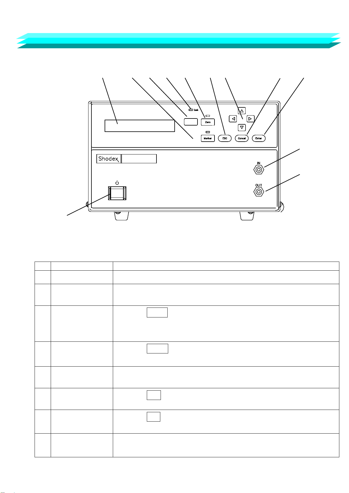
Fig. 5-1 Front Panel of Shodex CD-200
No. Name of part Function
□
1 Power Switch Press this key once to turn the unit on or off.
□
2 LCD Display A 24-digit 2-row character display panel. This is used for
displaying or setting various parameters.
□
3 Marker key
[Marker]
Press the Marker key to generate an event marker signal and add it
to the recorder output. While this function is active, the LED above the
key will be lit.
□
4 Display change key
[Display]
Press the Display key to toggle between S display and ΔS.
□
5 Leak LED
[Leak]
Illuminated when solvent leak is detected.
□
6 Auto Zero Key
[Zero]
Press the Zero key to activate “Auto-Zero”. While this
Function is active
,
the LED above
t
he ke
y
will be lit.
□
7 ESC Key
[ESC]
Press the ESC key to cancel an operation and return to the
normal screen.
□
8 Arrow Keys
[▲▼
▲
▼
]
Press the Arrow keys to move cursor or to edit values.
- 6 -
CD-200
Conductivity Detector
Display
5-2 Side Panel
□
13
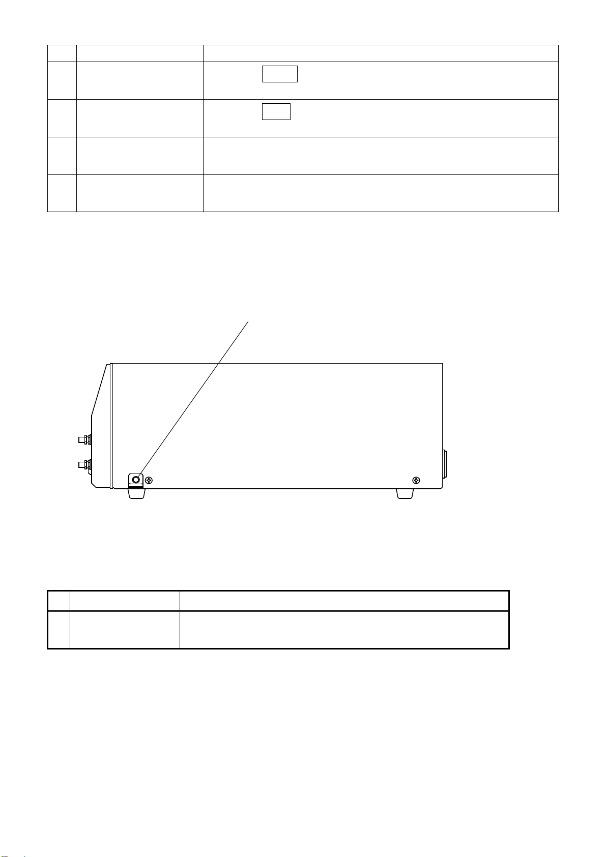
Fig. 5.2 Side panel of Shodex CD-200
No. Name of part Function
□
13 Drain Port In case of internal eluent leak, the eluent will be discharged from
this port. Connect the attached tubing as necessary.
- 7 -
No. Name of part Function
□
9 Cancel Key
[Cancel]
Press the Cancel key to cancel change and to stop beeping.
□
10 Enter Key
[Enter]
Press the Enter key to finalize operations or settings.
□
11 Inlet Port
[IN]
Connects tubing from separation column outlet.
□
12 Outlet Port
[OUT]
Eluent passing through the flow path is discharged from this port.
5-3 Back Panel
□
21 □
22 □
23
□
20
□
19
□
18
□
17 □
24
□
16
□
15 □
25
□
14
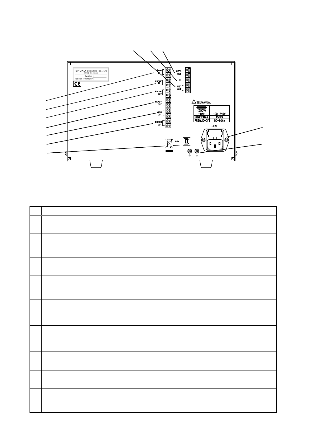
Fig. 5.3 Back panel of Shodex CD-200
No. Name of part Function
□
14 Communication port
[COM] USB communication port
□
15 Error out terminals
[ERROR OUT]
A contact signal is sent out through these terminals when
an error occurs.
□
16 Leak out terminals
[LEAK OUT]
A contact signal is sent out through these terminals when
an eluent leak is detected.
□
17 Ready out terminals
[READY OUT]
A contact signal is sent out through these terminals when
10 minutes have passed since the temperature of the cell has
reached the designated value.
□
18
Marker output
terminals
(MARKER OUT)
A contact signal (approx. a quarter second in duration) is sent out
through these terminals when marker is in operation.
□
19
Marker input
terminals
(MARKER IN)
Shortcircuiting these terminals gives the same effect as pushing
the marker switch (□
3).
□
20 Zero terminals
(ZERO)
Shortcircuiting these terminals gives the same effect as pushing
the zero switch (□
6).
□
21 Recorder terminals
[REC. OUT]
Signals to the recorder are sent out through these terminals.
The sensitivity of the output signal is 10 mV/FS.
□
22
Ground terminal
for the signal cable
[FG]
The shield terminal of the signal cable should be connected to
this terminal.
- 8 -
CD-200
T2.0A

No. Name of part Function
Integrator terminals
[INTEG. OUT]
Signals to the data processing unit are sent out through these
terminals. The sensitivity of the output signal is 200, 20, or 2
mV/(mS/m) with the integrator range of 5.12, 51.2, or 512 mS/m/FS .
Power connector
[~LINE]
The included power cable should be plugged into this connector.
Ground terminals
[ ]
These are the terminals to ground the main body of the detector.
- 9 -
□
23
□
24
□
25

5-4 Display
The display shows a “Monitor screen” when the detector is started and can be switched
to a “Parameter setting screen” when the W key or the X key is pressed.
<Monitor screen> <Parameter setting screen>
X S 123.4 mS/m 45℃ X * PARAMETERS * X
W RD W * SETTING * W
<Monitor screen>
□
26 □
27 □
28 □
29 □
30
AA
XXX.X mS/m XX ゚C
AAAAAAAAAAAAAAAA AA
No. Function
□
26 When the nominal value of conductivity displayed in □
27 is the electrical
conductivity of a background, "S" is displayed, and when the displayed value is
differential conductivity, "ΔS" is displayed.
□
27 This indicates whether the displayed value is electrical conductivity of a background
or differential conductivity.
□
28 This indicates the temperature of the cell.
□
29
This indicates error or operation status.
If there are multiple messages to be displayed, the priority message is displayed.
(1) ROM : Is displayed when a ROM error has occurred.
(2) RAM : Is displayed when a RAM error has occurred.
(3) PARAMETER : Is displayed when a parameter memory error has occurred.
(4) LEAKAGE : Is displayed when eluent leakage has occurred.
(5) SENSOR ERROR : Is displayed when the temperature sensor has a problem.
(6) OVER HEAT : Is displayed when the temperature is excessively high.
(7) ZERO OVER: Is displayed when Auto Zero does not function correctly.
(8) COMMUNICATION : Is displayed when a communication error has occurred.
(9) TEMP. UNSTABLE : After the detector is started, this remains displayed
until the temperature remains within ± 1°C of the set
temperature for 10 minutes.
□
30
One of the following is displayed in response to the detector status.
(1) LK : Key Lock status
(2) ER : Error status
(3) RD : Stable temperature status
- 10 -

<Parameter setting screen>
To show the currently set parameters in order, press the ▼ key or the ▲ key
while the parameter setting screen is displayed.
▼ ▲
▼ ▲
▼ ▲
▼ ▲
▼ ▲
▼ ▲
▼ ▲
▼ ▲
▼ ▲
▼ ▲
▼ ▲
- 11 -
PARAMETERS
REC.RANGE XXX mS/m
PARAMETERS
TEMPERATURE XX ℃
PARAMETERS
TIME CONSTANT X.X sec
PARAMETERS
POLARITY A
PARAMETERS
BASELINE SHIFT XXX
PARAMETERS
LEAK SENSOR AA
PARAMETERS
KEY LOCK AAA
PARAMETERS
DEFAULT AAA
PARAMETERS
INTEG.RANGE XXX mS/m
* PARAMETERS *
* SETTING *

To change parameters, perform the following procedures:
(1) Display the relevant parameter.
(2) Press the Enter key. The underlined digits will flash and the parameter can be changed.
(3) Press the T key or the S key to change the parameter with reference to Table 5-1.
(4) Press the ENTER key to finalize the parameter.
(5) Press the ESC key to return to the monitor screen.
Table 5-1 Settable parameters
NParameter Selectable value Unit Default
1 INTEG. RANGE 5.12, 51.2, 512 mS/m/1024mV 512
2 REC. RANGE
(INTEG. RANGE;5.12)
0.0025,0.005,0.01,0.02,0.04,0.08,
0.16,0.32,0.64,1.28,2.56,5.12 (12
Steps)
(INTEG. RANGE;51.2)
0.025,0.05,0.1,0.2,0.4,0.8,1.6,
3.2,6.4,12.8,25.6,51.2 (12 Steps)
(INTEG. RANGE;512)
0.25,0.5,1,2,4,8,16,32,64,128,
256,512 (12 Steps)
mS/m/10mV 512
3 TEMPERATURE OFF,30-50 (1 Step) ℃ 45
4 TIME CONSTANT 0.1,0.25,0.5,1,1.5,2,3,6
(8 Steps) sec 1
5 POLARITY +,- - +
6 BASELINE SHIFT 0-200 (50 nRIU increment) - 0
7 LEAK SENSOR ON,OFF - ON
8 KEY LOCK YES,NO - NO
9 DEFAULT DATA YES,NO - NO
- 12 -

6. Installation and connections
6-1 Power Connection and Grounding
Connect the detector to the power source according to the following procedure:
1) Confirm that the power socket into which the detector power cable
is plugged is of a 3P type with a grounding terminal.
2) Confirm that the voltage of the power socket into which the detector power cable is
plugged is the same as the voltage indicated on the rear panel of the detector.
3) Turn off the power switch □
1 of the detector.
4) Connect the Power connector □
24 of the detector rear panel to the power source
using the accessory power cable.
Prior to connection, make sure that the voltage of the power socket into
which the detector power cable is plugged is the same as the power supply
voltage indicated on the detector.
The power socket into which the detector power cable is plugged
should be of a 3P type with a grounding terminal. Other types of power sockets
should not be used.
The accessory power cable should be used to connect the detector to the
power socket. Other cables should not be used.
Do not use the detector in places where combustible gas or any source of
fire or spark exists or might exist.
As the detector is readily affected by the ambient temperature, use it in
places where there is little wind or change in ambient temperature.
Do not use the detector near any source of vibration or electrical noise or in
places where corrosive gas and a lot of dust are present.
Please do not set other equipment on this detector, in order to
avoid enlarging the baseline drift and losing control of the temperature.
- 13 -
!
Warning
!
Warning
!
Warning
!
Warning
Caution
Notice
Table of contents
Popular Security Sensor manuals by other brands


Prime Controls
Prime Controls SD220 operating instructions

AGFA
AGFA XD 17 user manual

Inficon
Inficon Sensistor ISH2000 HySpeed operating instructions

Powerfix Profi
Powerfix Profi 278296 Operation and safety notes

THORLABS
THORLABS PDA10PT user guide

PCB Piezotronics
PCB Piezotronics HT352B01 Installation and operating manual


