Shopseries RK7033 User manual

RK7033
10˝ DRILL PRESS PAGE 7 ENG
TALADRO DE COLUMNA DE 10 PULG. PAGE 13 ESP
PERCEUSE À COLONNE 10 PO PAGE 20 FRE

Thank you for purchasing a SHOPSERIES®power tool. We are confident that you will appreciate
the quality of the product and you will be entirely satisfied with your purchase. Please read
carefully the user safety and operating instructions on how to operate this product correctly
within safety norms and regulations.
Gracias por su compra de un producto SHOPSERIES®. Estamos seguros de que apreciará
la calidad del producto y de que estará completamente satisfecho con su compra. Lea
cuidadosamente las instrucciones de seguridad y de operación para obtener mayor información
acerca de cómo utilizar éste producto correctamente dentro de las normas y reglas de
seguridad.
Merci d’avoir choisi un produit de marque SHOPSERIES®. Nous sommes certains que ous
apprécierez la qualité de ce produit et qu’il saura vous satisfaire. Pour être renseigné sur toutes
les méthodes de travail correctes et sécuritaires répondant aux normes et règlements de
sécurité, veuillez lire attentivement la notice de sécurité et de fonctionnement présentée.
RK7033
A
117
16
2
4
5
6
78
9
11
12
13
14
15
B
9
b
c
a
D
C
EF
G2
H2
d
b
b
11
d
e
8
10
9
G1
H1
RK7033
A
117
16
2
4
5
6
78
9
11
12
13
14
15
B
9
b
c
a
D
C
EF
G2
H2
d
b
b
11
d
e
8
10
9
G1
H1
RK7033
A
117
16
2
4
5
6
78
9
11
12
13
14
15
B
9
b
c
a
D
C
EF
G2
H2
d
b
b
11
d
e
8
10
9
G1
H1
J
I
KL
NM
PO
Q
f
E
D
C
B
A
A
B
C
D
E
620
1100
1720
2340
3100
3
14
RK7033
J
I
KL
NM
PO
Q
f
E
D
C
B
A
A
B
C
D
E
620
1100
1720
2340
3100
3
14

7
10˝ DRILL PRESS ENG
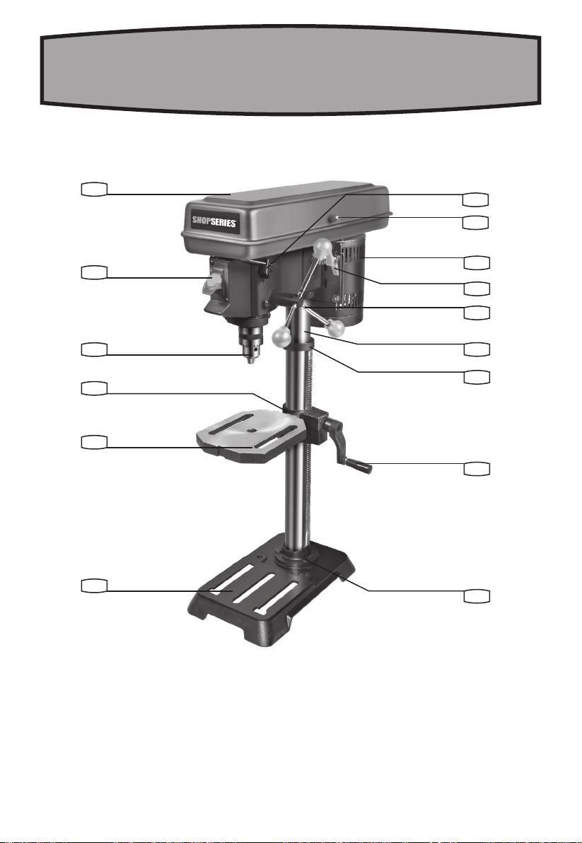
COMPONENT LIST
BELT COVER
ON / OFF SWITCH
DEPTH SCALE (See Fig. N)
CHUCK
BEVEL SCALE
WORKTABLE
MACHINE BASE
FIXING BOLT
TABLE CRANK HANDLE
WORKTABLE LOCKING HANDLE (See Fig. E)
COLUMN COLLAR
COLUMN
FEED HANDLE
BELT TENSION LOCKING KNOB
MOTOR
BELT COVER LOCKING SCREW
CHUCK KEY STORAGE
1
2
3
4
5
6
7
8
9
10
11
12
13
14
15
16
17
ACCESSORIES
Chuck key 1
Allen keys 2
We recommend that you purchase your accessories from
the same store that sold you the tool. Use good quality
accessories marked with a well-known brand name.
Choose the type according to the work you intend to
undertake. Refer to the accessory packaging for further
details. Store personnel can assist you and offer advice.
WARNING! Some dust created by power
sanding, sawing, grinding, drilling and
other construction activities contains chemicals
known to the State of California to cause cancer,
birth defects or other reproductive harm. Some
examples of these chemicals are:
•Lead from lead-based paints;
•Crystalline silica from bricks and cement and
other masonry products and
•Arsenic and chromium from chemically-treated
lumber.
Your risk from these exposures varies, depending
on how often you do this type of work. To reduce

8
10˝ DRILL PRESS ENG
your exposure to these chemicals: work in a well
ventilated area, and work with approved safety
equipment, such as those dust masks that are
specially designed to filter out microscopic particles.
California proposition 65:
WARNING: This product may contain lead,
phthalate or other chemicals known to the
State of California to cause cancer, birth defects
and other reproductive harm. Wash your hands
after use.
READ ALL INSTRUCTIONS
BEFORE USING THIS APPLIANCE
INSTRUCTIONS PERTAINING TO A RISK OF INJURY
GENERAL
A. GROUNDING INSTRUCTIONS
1. All grounded, cord-connected tools:
In the event of a malfunction or breakdown,
grounding provides a path of least resistance for
electric current to reduce the risk of electric shock.
This tool is equipped with an electric cord having an
equipment-grounding conductor and a grounding
plug. The plug must be plugged into a matching outlet
that is properly installed and grounded in accordance
with all local codes and ordinances.
Do not modify the plug provided – if it will not fit the
outlet, have the proper outlet installed by a qualified
electrician.
Improper connection of the equipment-grounding
conductor can result in a risk of electric shock. The
conductor with insulation having an outer surface that
is green with or without yellow stripes is the equipment-
grounding conductor. If repair or replacement of the
electric cord or plug is necessary, do not connect the
equipment-grounding conductor to a live terminal.
Check with a qualified electrician or service personnel
if the grounding instructions are not completely
understood, or if in doubt as to whether the tool is
properly grounded.
Use only 3-wire extension cords that have 3-prong
grounding plugs and 3-pole receptacles that accept
the tool’s plug.
Repair or replace damaged or worn cord immediately.
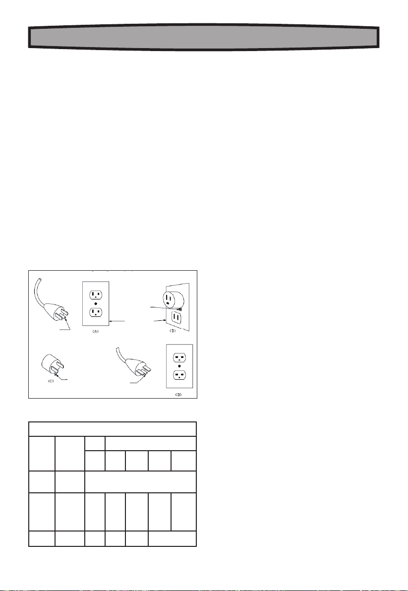
2. Grounded, cord-connected tools intended for
use on a supply circuit having a nominal rating
less than 150V:
This tool is intended for use on a circuit that has an
outlet that looks like the one illustrated in Sketch
A in Figure 1. The tool has a grounding plug that
looks like the plug illustrated in Sketch A in Figure
1. A temporary adapter, which looks like the adapter
illustrated in Sketches B and C, may be used to
connect this plug to a 2-pole receptacle as shown
in Sketch B if a properly grounded outlet is not
available. The temporary adapter should be used only
until a properly grounded outlet can be installed by
a qualified electrician. The green-colored rigid ear,
lug and the like, extending from the adapter must be
connected to a permanent ground such as a properly
grounded outlet box.
3. Grounded, cord-connected tools intended for
use on a supply circuit having a nominal rating
between 150-250V, inclusive:
This tool is intended for use on a circuit that has an
outlet that looks like the one illustrated in Sketch D in
Figure 1. The tool has a grounding plug that looks like
the plug illustrated in Sketch D in Figure 1. Make sure
the tool is connected to an outlet having the same
configuration as the plug. No adapter is available
or should be used with this tool. If the tool must be
reconnected for use on a different type of electric
circuit, the reconnection should be made by qualified
service personnel; and after reconnection, the tool
should comply with all local codes and ordinances.
4. Permanently connected tools:
This tool should be connected to a grounded metal
permanent wiring system; or to a system having an
equipment-grounding conductor.
B. FOR ALL DOUBLE-INSULATED TOOLS
1. Replacement parts
When servicing use only identical replacement parts.
2. Polarized Plugs
To reduce the risk of electric shock, this equipment
has a polarized plug (one blade is wider than the
other). This plug will fit in a polarized outlet only one
way. If the plug does not fit fully in the outlet, reverse
the plug. If it still does not fit, contact a qualified
electrician to install the proper outlet. Do not change
the plug in any way.
C. FOR ALL TOOLS AS APPLICABLE
1. Keep guards in place and in working order.
2. Remove adjusting keys and wrenches. Form
habit of checking to see that keys and adjusting
wrenches are removed from tool before turning it on.
3. Keep work area clean. Cluttered areas and
benches invite accidents.

9
10˝ DRILL PRESS ENG
4. Don’t use in dangerous environment. Don’t use
power tools in damp or wet locations, or expose them
to rain. Keep work area well lighted.
5. Keep children away. All visitors should be kept safe
distance from work area.
6. Make workshop kid proof with padlocks, master
switches, or by removing starter keys.
7. Don’t force tool. It will do the job better and safer at
the rate for which it was designed.
8. Use right tool. Don’t force tool or attachment to do a
job for which it was not designed.
9. Use proper extension cord. Make sure your
extension cord is in good condition. When using an
extension cord, be sure to use one heavy enough
to carry the current your product will draw. An
undersized cord will cause a drop in line voltage
resulting in loss of power and overheating. Table 1
shows the correct size to use depending on cord
length and nameplate ampere rating. If in doubt, use
the next heavier gage. The smaller the gage number,
the heavier the cord.
10. Wear proper apparel. Do not wear loose clothing,
gloves, neckties, rings, bracelets, or other jewelry
which may get caught in moving parts. Nonslip
footwear is recommended. Wear protective hair
covering to contain long hair.
11. Always use safety glasses. Also use face or
dust mask if cutting operation is dusty. Everyday
eyeglasses only have impact resistant lenses, they
are NOT safety glasses.
12. Secure work. Use clamps or a vise to hold work
when practical. It’s safer than using your hand and it
frees both hands to operate tool.
13. Don’t overreach. Keep proper footing and balance
at all times.
14. Maintain tools with care. Keep tools sharp and
clean for best and safest performance. Follow
instructions for lubricating and changing accessories.
15.
Disconnect tools before servicing; when changing
accessories, such as blades, bits, cutters, and the like.
16. Reduce the risk of unintentional starting. Make
sure switch is in off position before plugging in.
17. Use recommended accessories. Consult the
owner’s manual for recommended accessories. The
use of improper accessories may cause risk of injury
to persons.
18. Never stand on tool. Serious injury could occur if
the tool is tipped or if the cutting tool is unintentionally
contacted.
19.Check damaged parts. Before further use of the
tool, a guard or other part that is damaged should
be carefully checked to determine that it will operate
properly and perform its intended function – check
for alignment of moving parts, binding of moving
parts, breakage of parts, mounting, and any other
conditions that may affect its operation. A guard
or other part that is damaged should be properly
repaired or replaced.
20.Direction of feed. Feed work into a blade or cutter
against the direction of rotation of the blade or cutter
only.
21. Never leave tool running unattended. Turn
power off. Don’t leave tool until it comes to a
complete stop.
Figure 1
Grounding methods
GROUNDIN
G PIN
ADAPTER
GROUNDIN
GMEANS
GROUNDING
PIN
METAL SCREW
COVER OF
GROUND OUTLET
BOX
GROUNDING
PIN
GROUNDING
ADAPTER
OUTLET COVER
Table 1
Minimum gage for corda
Ampere
Rating
Volts Total length of cord in feet
120V
240V
25ft.
50ft.
50ft.
100ft.
100ft.
200ft.
150ft.
300ft.
More Than
Not More
Than AWG
0
6
10
6
10
12
18
18
16
16
16
16
16
14
14
14
12
12
12 16 14 12
Not Recommended

10
10˝ DRILL PRESS ENG
ADDITIONAL SAFETY
INSTRUCTIONS FOR DRILL PRESS
For Your Own Safety Read Instruction Manual
Before Operating Tool
a) Wear eye protection.
b) Do not wear gloves, necktie, or loose clothing.
c) Clamp workpiece or brace against column to prevent
rotation.
d) Use recommended speed for drill accessory and
workpiece material.
SAVE THESE INSTRUCTIONS
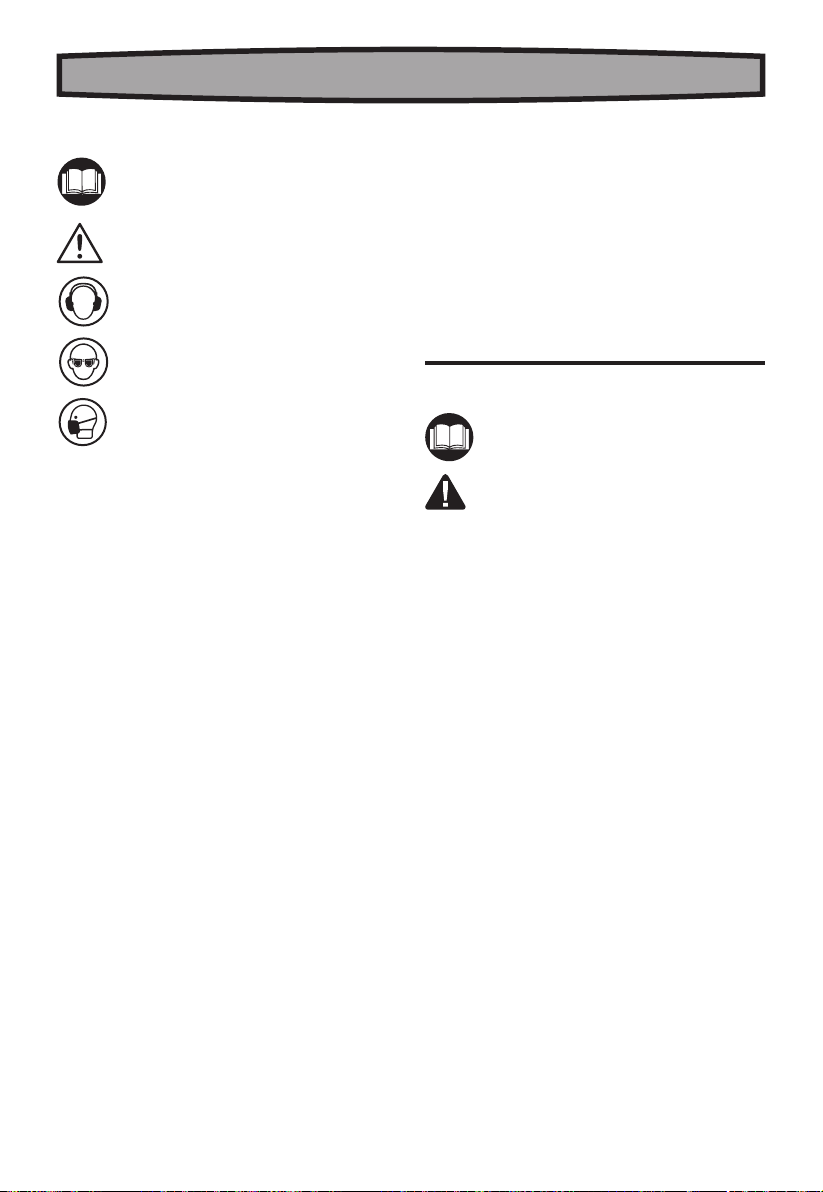
SYMBOLS
Read the manual
Warning
Wear ear protection
Wear eye protection
Wear dust mask
noNo-load speed
TECHNICAL DATA
Voltage 120 V-60 Hz
Amps 6.2 A
Rated speed 620-3100/min
Swing 10˝
Spindle travel 2˝
Table size 8˝ x 6-1/2˝
Throat depth 4-15/16˝
Table bevel range 0-45oLeft & Right
Speed settings 5
Weight 48.3 lbs
OPERATING INSTRUCTIONS
NOTE: Before using the tool, read the instruction
book carefully.
WARNING: To prevent personal injury, do not
connect the machine to the power source until
the machine is completely assembled and you have read
and understand the entire instruction manual. Always
disconnect the plug from the power source before
assembling parts, making adjustments or changing drill
bits.
ASSEMBLY
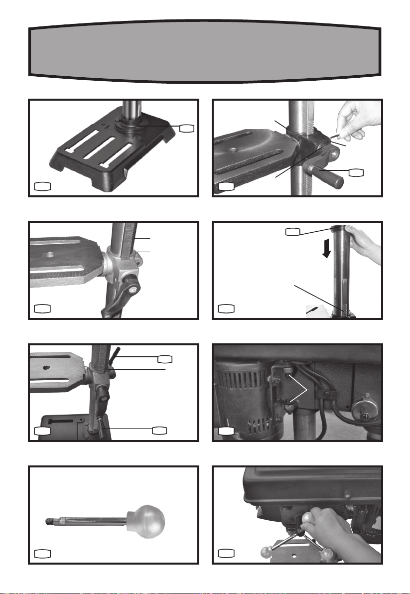
1. ASSEMBLY OF MACHINE BASE/COLUMN
1) Position Machine Base on floor (See Fig.A)
Remove protective sleeve from Column tube and
discard. Place Column assembly onto Machine Base,
and align holes on the Column support with holes on
the Base.
Install a bolt in each hole (through Column support
and Base) and tighten the Fixing Bolts (8) with
adjustable wrench.
2. ASSEMBLY OF THE TABLE CRANK
1) Locate the Elevation Worm Gear and the Table Crank
(need new reference image). Insert the Worm Gear
into the Table Crank so when you turn the handle the
gear properly rotates. Then loosen the set-screws on
the back of the Table Crank so it may easily fit over the
Column (reference C in image B).
2) Remove the Collar from the Column. The long smooth
end of the Column should be the top.
3) Place the Raising Rack on the right side of the Column
(from a front perspective) and ensure that the bottom
of the Rack is aligned inside the flange on the base
of the Column. While holding Rack, slide the Table

11
10˝ DRILL PRESS ENG
Crank over the Column so the Rack and Table Crank fit
accordingly as seen in image C.
4) Tighten the Table Crank Screws (C) seen in reference
image (B). When properly fitted, the Table Crank
should raise and lower when the handle is being
cranked.
5) Replace the Column Collar by sliding it back over the
Column so the bevel side is facing down. Slide the
Collar down over the raising Rack as seen in image D.
IMPORTANT: Column Collar MUST NOT be pushed all
the way down onto the top of the raising rack. MAKE
SURE top of the raising rack is under bottom of ring and
that there is enough clearance to allow the raising rack to
rotate around the column. Check Column Collar for proper
adjustment. Collar should not be angled on the column
and it should be positioned so that the rack will slide
freely when table is rotated 360º around the column tube.
NOTE: To avoid Column or Collar damage, do not over-
tighten the set screw.
5) Locate Worktable Locking Handle (10) (in loose parts
bag). Thread the Worktable Locking Handle into the
hole in the rear of the table support bracket, from left
side, and tighten it by hand. (See Fig. E)
2. ASSEMBLY OF DRILL PRESS HEAD (See Fig. F)
Before assembly of the drill press head, you should
loosen the head locking screws. To attach the drill press
head onto the Column, carefully lift the head above the
Column tube and slide it onto the Column, making sure
the head slides down onto the Column as far as possible.
Align the head with the Table and the Base. Tighten the
2 head locking screws (e) located on the left side of the
head by using a 0.16” ( 4mm) hex wrench.
CAUTION: The head assembly weighs
approximately 40 pounds. Get help when needed.
3. ASSEMBLY OF FEED HANDLES (See Fig. G1 & G2)
Locate the 3 Feed Handles. Thread the Handles into the
three holes located in the pinion shaft hub located on the
side of the drill press head.
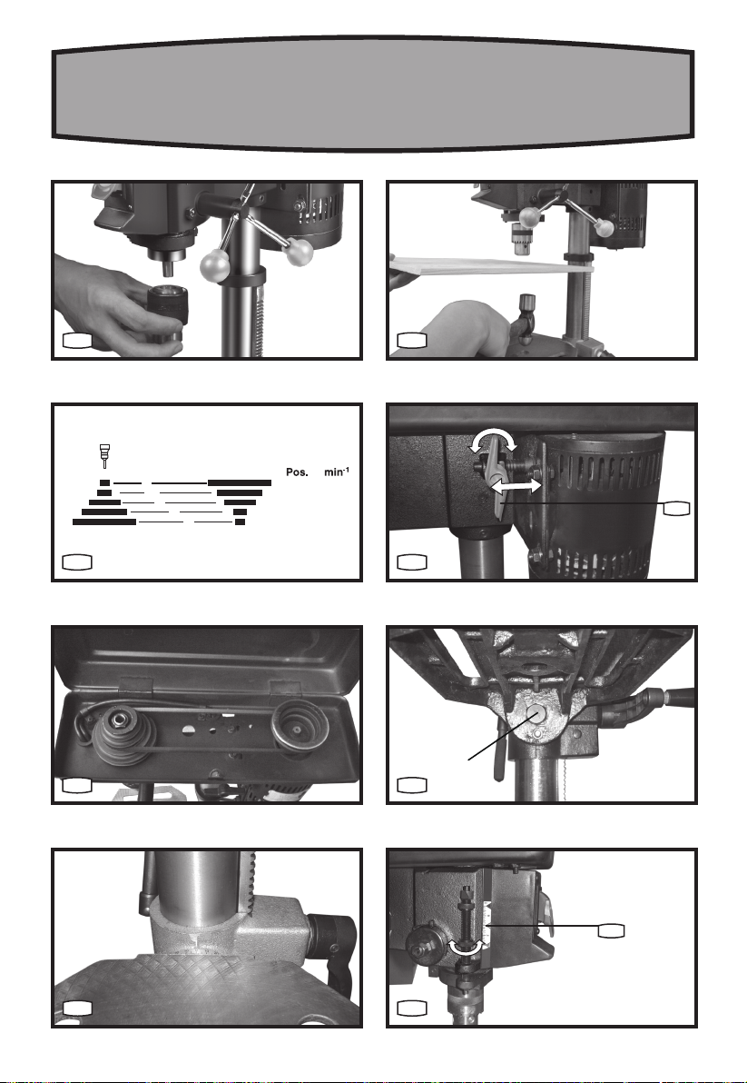
4. ASSEMBLY OF CHUCK (See Fig. H1 & H2)
1) To install the Chuck, clean out the tapered hole in
the Chuck and clean the spindle taper on the drill
press head using a clean cloth.
NOTE: Both tapered surfaces must be clean of oil, grease
and dirt. A piece of dirt on any of these surfaces will
prevent the chuck from seating properly.
2) Open the Chuck jaws as wide as possible by turning
the Chuck sleeve. Slide the Chuck onto the tapered
spindle on the drill press head. (See H1)
3) Holding the Chuck on the spindle, tap with a block
of wood and hammer or a soft tip hammer to set the
Chuck onto the spindle. (See Fig. H2)
CAUTION: Never drive the Chuck onto the spindle using a
metal hammer as this could damage the Chuck.
ADJUSTMENTS
NOTE: Always disconnect the power supply before
making any adjustments to the machine.
1. SPINDLE SPEED (See Fig. I)
Five different spindle speeds allow you to drill a wide
variety of material including wood, plastic, and metal.
Refer to speed chart and select the speed required for
the job at hand. The machine has 5 speed settings: 620-
3100 RPM.
2. CHANGING SPEEDS (See Fig. J, K)
The spindle speed is determined by the location of the
belt on the pulleys inside the head assembly.
To change the pulley configuration:
Loosen the Belt Cover Locking Screw and lift up the Belt
Cover.
Loosen the Belt Tension Locking Knob(14).
Move the belt to the correct pulley step for the desired
speed.
Push motor backward until moderate Belt Tension is
acquired. (See J)
Retighten the Belt Tension Locking Knob.
WARNING: Use the recommended speed
for the drill bit and the workpiece
material.
3. WORK TABLE ADJUSTMENT
1) Loosen the Locking Screw at the rear of the table.
Move the table up or down the Column until the
desired height is reached and lock the table into
position. Re-tighten the Locking Screw.
2) The Worktable can rotate ±45° to left or right.
Slacken the locking nut (f) underneath the Table
with a wrench and rotate the table to the desired
angle. Re-tighten the locking nut. (See Fig. L, M)
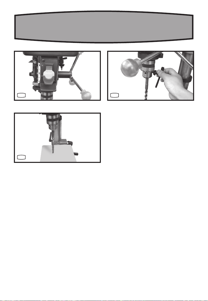
4. ADJUSTING THE DRILLING DEPTH (See Fig. N)
To adjust the drilling depth when you need to drill a
number of holes to exactly the same depth:
Rotate depth scale locking knob to desired setting.

12
10˝ DRILL PRESS ENG
OPERATION
1. STARTING AND STOPPING THE MACHINE
(See Fig. O)
To turn the machine on, move the Switch up to the “ON”
position. To turn it off, move the Switch down to the
“OFF” position.
To “Lock-off” the machine:
When the machine is not in use and to prevent
unauthorized use, the Switch should be locked in the
“OFF” position. To do this, pull the locking key out of the
ON/OFF Switch and store the key in a secure place. With
the key removed, the Switch will not operate.
2. INSTALLING AND REMOVING BITS (See Fig. P)
Unplug the drill press.
Open or close the Chuck jaws to a point where the
opening is slightly larger than the bit size you intend to
use.
Insert drill bit into the Chuck the full length of the jaws.
Tighten Chuck jaws securely using Chuck Key provided.
Tighten all three Chuck jaws evenly and sufficiently to
hold the bit securely. Do not use a wrench to tighten or
loosen Chuck jaws.
Remove Chuck Key.
To remove the drill bit, reverse the steps listed above.
3. DRILLING (See Fig. Q)
Select the proper drill bit based on the desired hole size.
For large holes, drill a pilot hole first, using a smaller
diameter bit.
Unlock the depth scale lock knob. Using the Feed
Handles, set the spindle at the desired depth and
retighten the lock knob securely.
Turn the Table Crank Handle, and set the Table to desired
height.
NOTE: Make sure the Table is free of all loose objects and
the bit is not in contact with the workpiece.
Plug the electrical cord into power supply and turn the
switch ON. Make sure spindle rotates freely.
Slowly lower drill bit into workpiece. Do not force the bit;
let the drill press do the work.
4. DRILLING TIPS
If a large hole is needed, it’s a good idea to drill a smaller
pilot hole before drilling the final one. Your hole will be
more accurately positioned, rounder, and the bits will last
longer.
If the hole is deeper than it is wide, back off occasionally
to clear the chips.
When drilling metal, lubricate the bit with oil to improve
drilling action and increase bit life.
As you increase the bit size, you may need to reduce the
spindle speed.
If drilling a through hole, make sure that the bit will not
drill into the table after moving through the workpiece.
MAINTAIN TOOLS WITH CARE
Keep tools sharp and clean for better and safer performance.
Follow instructions for lubricating and changing accessories.
Inspect tool cords periodically and if damaged, have repaired by
authorized service facility.
Your power tool requires no additional lubrication or maintenance.
There are no user serviceable parts in your power tool. Never use
water or chemical cleaners to clean your power tool. Wipe clean
with a dry cloth. Always store your power tool in a dry place. Keep
the motor ventilation slots clean. Keep all working controls free of
dust. If you see some sparks flashing in the ventilation slots, this
is normal and will not damage your power tool.
If the supply cord is damaged, it must be replaced by the
manufacturer, its service agent or similarly qualified persons in
order to avoid a hazard.
Drilling speed table(min)
Drill Bit
Diam
(Inches)
Material
Wood Alum, Zinc,
Brass Iron, Steel
1/16
3100
3100
3100
1/8 2340
3/16 1720
1/4 2340
5/16 1100
3/8 1720
1/2 2340 1100 620

13
TALADRO DE COLUMNA DE 10 PULG. ESP
ACCESORIOS
Llave de mandril 1
Llave allen 2
Le recomendamos que compre todos los accesorios en
la tienda donde adquirió la herramienta. Use accesorios
de buena calidad una marca bien conocida. Seleccione
los que más convengan al trabajo que intenta hacer.
Consulte el empaque de los accesorios para obtener más
detalles. El personal de la tienda también puede ayudarle
y aconsejarle.
¡ADVERTENCIA! El polvo originado por la
utilización de herramientas motorizadas
contiene químicos que, según el Estado de
California, causan cáncer, defectos congénitos y
otros daños reproductivos. Algunos ejemplos de
esos productos químicos son:
•El plomo de las pinturas a base de plomo
•La sílice cristalina de los ladrillos, del
cemento y de otros productos de albañilería
•El arsénico y el cromo de la madera tratada
químicamente
El riesgo que se corre a causa del contacto con
esos productos varía según la frecuencia con
LISTA DE PARTES
CABEZAL
LLAVE DE ENCENDIDO
ESCALA DE PROFUNDIDAD
PORTABROCAS
ESCALA DE BISELADO
MESA DE TRABAJO
BASE
PERNOS DE MONTAJE
MANIVELA DE ELEVACIÓN
MANGO DE BLOQUEO DE LA MESA DE TRABAJO
ABRAZADERA DE LA COLUMNA
COLUMNA
AGARRADERAS DE ALIMENTACIÓN
PERILLA PARA TRABAR LA TENSIÓN DE LA CORREA (EN AMBOS LADOS)
MOTOR
TORNILLOS DE LA CUBIERTA DE SEGURIDAD
ALMACENAMIENTO DE MANDRILES
1
2
3
4
5
6
7
8
9
10
11
12
13
14
15
16
17

14
TALADRO DE COLUMNA DE 10 PULG. ESP
que usted realice este tipo de trabajos. Con el
fin de reducir su exposición a esas substancias
químicas: trabaje en un área bien ventilada;
utilice un equipo de seguridad adecuado, tal
como una máscara contra el polvo especialmente
diseñada para filtrar partículas microscópicas.
California-Propuesta de ley núm. 65:
ADVERTENCIA: Este producto podría
contener plomo, ftalato y otros químicos
identificados por el Estado de California como
causantes de cáncer, defectos congénitos y otras
lesiones reproductivas. Lave sus manos después
de cada uso.
LEA Y COMPRENDA TODAS LAS
INSTRUCCIONES
CONSERVE ESTAS INSTRUCCIONES
INSTRUCCIONES DE SEGURIDAD
A. INSTRUCCIONES DE CONEXIÓN A TIERRA
1. Todas las máquinas conectadas con cordón a tierra:
En caso de mal funcionamiento o avería, la conexión
a tierra proporciona una ruta de resistencia mínima
para la corriente eléctrica, con el fin de reducir
el riesgo de descargas eléctrica. Esta máquina
está equipada con un cordón eléctrico que tiene
un conductor de conexión a tierra del equipo y
un enchufe de conexión a tierra. El enchufe debe
enchufarse en un tomacorriente coincidente que esté
instalado y conectado a tierra adecuadamente, de
acuerdo con todos los códigos y ordenanzas locales.
No modifique el enchufe suministrado.
—Si el enchufe no cabe en el tomacorriente, haga
que un electricista calificado instale el tomacorriente
apropiado.
La conexión inapropiada del conductor de conexión
a tierra del equipo puede dar como resultado
riesgo de descargas eléctricas. El conductor con
aislamiento que tiene una superficie exterior de color
verde con o sin franjas amarillas es el conductor de
conexión a tierra del equipo. Si es necesario reparar
o reemplazar el cordón eléctrico o el enchufe, no
conecte el conductor de conexión a tierra del equipo a
un terminal con corriente.
Consulte a un electricista competente o a personal
de servicio calificado si no entiende completamente
las instrucciones de conexión a tierra o si tiene dudas
en cuanto a si la máquina está conectada a tierra
apropiadamente.
Utilice únicamente cordones de extensión de tres
alambres que tengan enchufes de tipo conexión a
tierra con tres terminales y receptáculos de tres
conductores que acepten el enchufe de la maquina.
Repare o reemplace inmediatamente los cordones
dañados o desgastados.
2. Máquinas conectadas con cordón conectadas a
tierra diseñadas para utilizarse en un circuito
de alimentación que tenga una capacidad
nominal de menos de 150 V:
Si la máquina está diseñada para utilizarse en
un circuito que tenga un tomacorriente parecido
al que se ilustra en la A Fig1, la máquina tendrá
un enchufe de conexión a tierra que se parece al
enchufe ilustrado en la A Fig 1. Puede utilizarse un
adaptador temporal, que se parece al adaptador
ilustrado en la B&C, para conectar este enchufe a
un receptáculo coincidente de dos conductores, tal
como se muestra en la B, si no se dispone de un
tomacorriente conectado a tierra apropiadamente.
El adaptador temporal debe utilizarse solamente
hasta que un electricista calificado pueda instalar un
tomacorriente conectado a tierra apropiadamente.
La orejeta, lengüeta, etc., rígida de color verde que
sobresale del adaptador debe conectarse a una toma
de tierra permanente, como por ejemplo una caja
tomacorriente conectada a tierra adecuadamente.
Siempre que se utilice un adaptador, debe sujetarse
en su siton con un tornillo de metal.
3. Herramientas con conexión a tierra y
alimentación por cable destinadas al uso en un
circuito de alimentación con un voltaje nominal
de 150 - 250 V, ambos inclusive:
Si la máquina está diseñada para utilizarse en
un circuito que tenga un tomacorriente parecido
al que se ilustra en la D Fig 1, la máquina tendrá
un enchufe de conexión a tierra que se parece
al enchufe ilustrado en la D Fig 1. Asegúrese de
que la herramienta se encuentra conectada a una
toma de suministro eléctrico que tenga la misma
configuración que el enchufe. No existe ningún
adaptador disponible, ni deberá utilizarse ninguno
para conectar esta herramienta. Si es necesario
volver a conectar la herramienta para utilizarla con un
tipo diferente de circuito eléctrico, la nueva conexión
deberá ser realizada por personal técnico cualificado;
una vez realizada la nueva conexión, la herramienta
deberá satisfacer todas las normativas y ordenanzas
locales.

15
TALADRO DE COLUMNA DE 10 PULG. ESP
4. Herramientas continuamente conectadas:
Esta herramienta debe ser conectada a un sistema
de cableado de metal permanente y con descarga
a tierra o a un sistema que posea un conductor de
puesta a tierra de equipos.
B. PARA TODAS LAS HERRAMIENTAS CON DOBLE
AISLAMIENTO
1. Piezas de repuesto
Deben utilizarse únicamente piezas idénticas durante
las operaciones de reparación.
2. Enchufes polarizados.
Las herramientas con doble aislamiento están
equipadas con un enchufe polarizado (una pata
es más ancha que la otra). Este enchufe entrará
en un tomacorriente polarizado solamente de una
manera. Si el enchufe no entra por completo en
el tomacorriente, délo vuelta. Si sigue sin entrar,
póngase en contacto con un electricista competente
para instalar un tomacorriente polarizado. No haga
ningún tipo de cambio en el enchufe.
C. PARA TODAS LAS HERRAMIENTAS, SEGÚN SEA
PERTINENTE
1. Mantenga las guardas en su lugar y en
perfecto estado de funcionamiento.
2. Retire las llaves de ajuste. Asegúrese de
comprobar siempre que las llaves de ajuste no se
encuentren en lugar de la herramienta antes de
encenderla.
3. Mantenga limpia el área de trabajo. Las áreas
de trabajo y bancos desordenados podrían causar
accidentes.
4. No utilice la herramienta. No utilice la herramienta
motorizada en ambientes húmedos o mojados o
expóngala a la lluvia. Mantenga bien iluminada el área
de trabajo.
5. Mantenga a los niños alejados de la
herramienta. Todas las visitas deben mantener una
distancia apropiada del área de trabajo.
6. Asegúrese de que el taller sea seguro para
los niños utilizando candados, interruptores
generales o retirando las llaves de encendido.
7. No fuerce a la herramienta. Ésta realizará el
trabajo para el cual fue diseñado mejor y de manera
más segura.
8. Utilice la herramienta adecuada. No utilice una
herramienta o un accesorio para realizar un trabajo
para el cual no fue diseñado.
9. Utilice cables de extensión apropiados.
Cerciórese de que su cable prolongador esté en
buenas condiciones. Asegúrese de utilizar un
prolongador lo suficientemente resistente como para
soportar la corriente que requiere su producto. Un
cable pequeño causará una caída de corriente en la
línea de voltaje, dando por resultado recalentamiento
y pérdida de potencia. La Tabla 1 muestra el calibre
correcto a utilizar, dependiendo de la longitud
del cable y del amperaje indicado en la placa de
identificación. En caso de duda, utilice el tamaño
mayor siguiente. Cuanto menor es el calibre, mayor
es la capacidad del cable.
10. Vístase apropiadamente. No se ponga ropa
holgada ni joyas. Recójase el cabello largo.
Mantenga su cabello, ropa y guantes alejados de las
piezas móviles. Se recomienda utilizar un calzado
antideslizante. Utilice una gorra de protección para
colocar el cabello largo dentro de ésta.
11. Utilice siempre anteojos de seguridad. También
utilice una máscara facial o una máscara antipolvo
si la operación de corte es polvorienta. Los anteojos
comunes sólo poseen lentes resistentes a los
impactos y NO pueden ser considerados como
anteojos de seguridad.
12. Asegure la pieza de trabajo. Utilice abrazaderas o
un tornillo de banco para asegurar la pieza de trabajo
cuando sea necesario. Esto es más seguro debido
a que permite usar ambas manos para utilizar la
herramienta.
13. No intente alcanzar demasiado lejos. Mantenga
un apoyo de los pies y un equilibrio adecuados en
todo momento.
14. Realice con cuidado el mantenimiento de las
herramientas. Mantenga las herramientas limpias
con el fin de lograr el mejor rendimiento y el más
seguro. Siga las instrucciones de lubricación de las
herramientas y de cambio de accesorios.
15. Desconecte el enchufe de la fuente de
alimentación antes de hacer cualquier ajuste,
cambiar accesorios o guardar la herramienta.
16. Reduzca el riesgo de un encendido accidental.
Asegúrese de que el interruptor se encuentre
en la posición de apagado antes de enchufar la
herramienta.
17. Utilice los accesorios recomendados. Consulte el
manual de usuario para obtener información acerca
de los accesorios recomendados. La utilización de
accesorios no adecuados podría aumentar el riesgo
de causar lesiones a personas.
18. Nunca se pare sobre la herramienta. Podría
ocurrir una lesión grave si se cae la herramienta de
16
TALADRO DE COLUMNA DE 10 PULG. ESP
corte o si usted entra en contacto accidental con
ésta.
19. Controle las partes dañadas. Antes de comenzar
a utilizar la herramienta, controle la guarda o
cualquier otra parte que se encuentre dañada con
el fin de determinar que funcionará de manera
correcta y realizará la función para la cual fue
diseñada – controle la alineación de las partes
móviles, la sujeción de las partes móviles, la rotura de
partes, el montaje y cualquier otra condiciones que
podría afectar el funcionamiento de la herramienta.
Cualquier guarda o parte que se encuentre dañada
deberá ser reparada o reemplazada apropiadamente.
20. Dirección de la pieza de trabajo. Coloque la pieza
de trabajo en la hoja o cuchilla sólo en contra de la
dirección de rotación de la hoja o cuchilla.
21. Nunca deje funcionando sola a la herramienta.
Apáguela. No suelte la herramienta hasta que se haya
detenido por completo.
Fig 1
Métodos de conexión a masa
PUNTA DE
CONEXIÓN A
TIERRA
ADAPTADOR
ADAPTADOR
DE CONEXIÓN
A TIERRA
PUNTA DE
CONEXIÓN A
TIERRA
TORNILLO
METÁLICO
TOMACORRIENTE APA
TABLA 1
Calibre mínimo para el cable
Amperios
Cap
acidad
Voltios
Longitud total del cable en pies
120V
240V
25pies
50pies
50pies
100pies
100pies
200pies
150pies
300pies
Mayor de
No mayor de Calibre AWG
0
6
10
6
10
12
18
18
16
16
16
16
16
14
14
14
12
12
12 16 14 12
No se recomienda
INFORMACIÓN DE SEGURIDAD
ADICIONAL DE LA HERRAMIENTA
Para su seguridad, lea el manual de instrucciones
antes de utilizar el taladro prensa
a) Utilice protección ocular.
b) No utilice guantes, corbatas o vestimenta suelta.
c) Sujete con abrazaderas la pieza de trabajo o
asegúrela contra la columna con el fin de evitar que
ésta gire.
d) Utilice la velocidad recomendada para el accesorio
del taladro y el material de la pieza de trabajo.
CONSERVE ESTAS INSTRUCCIONES
17
TALADRO DE COLUMNA DE 10 PULG. ESP
SÍMBOLOS
no
DATOS TÉCNICOS
Voltios
Amperios
Velocidad sin carga
Profundidad
Carrera del husillo
Tamaño de la Mesa
Profundidad de la garganta
Inclinación de la mesa
Ajustes de velocidad
Peso
INSTRUCCIONES DE USO
NOTA: Antes de usar la herramienta, lea
atentamente el manual de instrucciones.
ADVERTENCIA: Para evitar heridas, no
conecte la máquina al tomacorriente hasta que
esté completamente armada y haya leído y comprendido
completamente el manual de instrucciones. Desconecte
siempre el enchufe del tomacorriente antes de armar
partes, hacer ajustes o cambiar brocas.
ENSAMBLE
1. ARMADO DE LA COLUMNA Y EL ESTANTE
1) Coloque la base en el piso. (Ver A)
Saque la funda protectora de la columna y
deséchela. Coloque el conjunto de la columna sobre
la base, alineando los agujeros del soporte de la
columna con los de la base.
Coloque un tornillo en cada agujero (a través del soporte
de la columna y la base) y ajústelos con una llave.
2)
Ubique el tornillo sin fin de elevación (a) (en la bolsa
de partes sueltas) y la manivela de la mesa. Inserte
el eje del tornillo sin fin de elevación en el soporte de
la mesa (b) y extiéndalo todo lo que pueda a través
de la abertura. Coloque la manivela de la mesa en el
eje con el tornillo de ajuste (c). El tornillo de ajuste
debe quedar alineado con la parte plana del eje. Debe
colocar la manivela de la mesa lo más cerca posible
del brazo de soporte, luego ajuste el tornillo con la
llave hexagonal. No ajuste los tornillos de más. (Ver B)
3)
Saque la abrazadera de la columna. Con el extremo largo
y liso de la bandeja (d) elevadora apuntando hacia arriba,
deslice con ambas manos todo el conjunto de la mesa y
la cremallera por la columna hasta que la parte inferior
de la cremallera quede colocada en el collar de la base y
contra la columna. (Ver C). Mientras sostiene la bandeja
contra el tornillo sin fin del soporte de la mesa, deslice el
Lea el manual
Advertencia
Use protección auditiva
Use lentes de seguridad
Use máscara contra el polvo
Velocidad sin carga
120 V-60 Hz
6.2 A
620-3100 rpm
10 pulg. (254 mm)
2 pulg. (50.8 mm)
8 pulg. x 6-1/2 pulg. (203 mm x 165 mm)
4-15/16 pulg. (125 mm)
0-45oizquierda y derecha
5
48.3 libras (22.0 kg)

18
TALADRO DE COLUMNA DE 10 PULG. ESP
soporte de la mesa (b) sobre el tubo de la columna.
4)
Vuelva a colocar la abrazadera de la columna deslizándola
nuevamente sobre la columna. Coloque la abrazadera de
modo que el lado biselado quede hacia abajo. Deslice la
abrazadera hacia abajo sobre la bandeja elevadora. (Ver D)
IMPORTANTE: No empuje la arandela de retención
completamente hasta abajo contra el tope de la bandeja
elevadora. VERIFIQUE que la parte de arriba de la bandeja
elevadora quede por debajo de la arandela y que haya
suficiente separación para permitir que la bandeja elevadora
rote alrededor de la columna. Verifique el ajuste correcto de
la abrazadera de la columna. La abrazadera no debe quedar
inclinada en la columna, y debe quedar colocada como para
que la bandeja se deslice libremente al rotar la mesa 360º
alrededor del tubo de la columna.
NOTA: Para evitar daños a la columna o la abrazadera, no
ajuste de más el tornillo.
5)
Ubique el mango de traba de la mesa (10) (en la bolsa
de partes sueltas). Atornille el mango de traba de la
mesa en el agujero de la parte de atrás del soporte de la
mesa, desde la izquierda, y ajústelo con la mano. (Ver E)
2. ARMADO DEL CABEZAL DEL TALADRO DE BANCO
(Ver F)
Antes de colocar el cabezal del taladro prensa, afloje el
tornillo de bloqueo del cabezal. Para colocar el cabezal
sobre la columna, levante cuidadosamente el cabezal
sobre el tubo de la columna y deslícelo sobre el mismo
verificando que entre lo máximo posible. Alinee el cabezal
con la mesa y la base. Ajuste los 2 (dos) tornillos (e)
de ajuste del cabezal en el lado derecho, con una llave
hexagonal de 0.16” (4mm).
CUIDADO: El cabezal pesa unas 40 libras. Obtenga
ayuda cuando sea necesario.
3. ARMADO DE LAS MANIJAS DE ALIMENTACIÓN
(Ver G1 & G2)
Ubique las 3 (tres) manijas de alimentación. Atornille las
manijas en los tres agujeros ubicados en el eje del piñón,
al costado del cabezal.
4. ARMADO DEL PORTABROCAS (Ver H1 & H2)
1) Para instalar el portabrocas, limpie el agujero cónico
del portabrocas y el tornillo cónico del cabezal con un
trapo limpio.
NOTA: Ambas superficies cónicas deben quedar sin aceite,
grasa o tierra. Un poco de tierra en cualquiera de estas
superficies evitará que el portabrocas quede colocado
correctamente.
2) Abra el portabrocas todo lo posible haciéndolo girar.
Coloque el portabrocas sobre el eje cónico del cabezal.
(Ver H1)
3) Sosteniendo el portabrocas sobre el eje, golpéelo con
un martillo y un bloque de madera o un martillo blando
para que se trabe en el eje. (Ver H2)
CUIDADO: Para evitar dañar el portabrocas, nunca lo
instale en el eje usando un martillo de metal.
AJUSTES
NOTA: Siempre desenchufe la herramienta antes de hacer
cualquier ajuste.
1. VELOCIDAD DE FIJACIÓN DEL HUSILLO (Ver I)
Las cinco diferentes velocidades del husillo permiten
taladrar una amplia variedad de materiales, como
madera, plástico y metal.
Vea el cuadro de velocidades y elija la necesaria para el
trabajo. La máquina tiene 5 ajustes de velocidad: 620-
3100 RPM.
2. CAMBIO DE VELOCIDAD (Ver J, K)
La velocidad del husillo está determinada por la
colocación de la correa en las poleas situadas dentro del
conjunto del cabezal.
Para cambiar el arreglo de las poleas:
Afloje el botón de bloqueo de cinturón y levantar el cinturón.
Afloje el perno de tensión.
Retire la correa de transmisión. Ajuste la posición de la
correa de conformidad con la tabla de velocidades.
Empuje el motor hacia el frente de la máquina para aflojar la
correa y hacia la parte de atrás para tensionarla. (Ver J)
Apriete de nuevo el perno de tensión.
ADVERTENCIA: Utilice la velocidad
recomendada para el accesorio de taladrar
y para el material de la pieza de trabajo.
3. AJUSTE DE LA MESA DE TRABAJO
1) Afloje el tornillo de bloqueo en la parte trasera de la
tabla. Mueva la mesa hacia arriba o hacia abajo por
la columna hasta obtener la altura deseada y vuelva
a trabarla en posición. Vuelva a ajustar la perilla de
fijación.
2) La mesa de trabajo puede rotar ±45o hacia la izquierda
o la derecha. Afloje la tuerca de traba que está debajo
de la mesa con una llave y rótela al ángulo deseado.
Vuelva a ajustar la tuerca de traba. (Ver L, M)
4. AJUSTE DE LA PROFUNDIDAD DE TALADRADO (Ver N)
Para ajustar la profundidad de taladrado cuando necesite
taladrar exactamente a la misma profundidad un cierto
número de agujeros:
Afloje la perilla de fijación.
Gire el graduador de profundidad a la marca deseada.
Vuelva a ajustar la perilla de fijación.

19
TALADRO DE COLUMNA DE 10 PULG. ESP
USO
1. INTERRUPTOR ENCENDIDO/APAGADO (Ver O)
La llave está ubicada en el frente del cabezal la máquina,
arriba del portabrocas. Para encender el taladro, mueva
la llave hacia arriba a la posición “ON”. Para apagar la
máquina, mueva la llave hacia abajo a la posición “OFF”.
Para “Trabar” la máquina:
Cuando no use la máquina y para evitar el uso no
autorizado, debe trabar la llave en la posición “OFF”. Para
hacerlo, saque la llave de traba de la llave de encendido
y guárdela en un lugar seguro. Sin la llave colocada, el
taladro no funcionará.
2. MONTAJE Y DESMONTAJE DE LAS BROCAS (Ver P)
Desconecte la taladradora de columna.
Abra o cierre las mordazas del portabrocas hasta que la
abertura sea levemente más grande que la brocadeseada.
Introduzca la broca en el portabrocas, en toda la
profundidad de las mordazas del mismo.
Apriete firmemente las mordazas con la llave suministrada
para el portabrocas. No utilice ninguna llave de tuercas
para apretar o aflojar las mordazas del portabrocas.
Retire la llave del portabrocas.
Para desmontar del portabrocas la broca, invierta el orden
de los pasos descritos arriba.
3. TALADRADO (Ver Q)
Seleccione la broca adecuada según el tamaño del
agujero deseado.
Para taladrar agujeros más grandes, taladre un agujero
guía primero con una broca de diámetro menor.
Afloje la palanca de fijación del husillo y la perilla de
fijación. Con las palancas de avance coloque el husillo a
la profundidad deseada y apriete fimemente de nuevo la
palanca y la perilla de fijación.
Con un giro de la manivela de ajuste de la mesa coloque
ésta a la altura deseada.
NOTA: Asegúrese de que la mesa esté libre de objetos sueltos
y de que la broca no esté en contacto con la pieza de trabajo.
Conecte el cordón eléctrico en el suministro de corriente y
encienda ENCIENDA el interruptor. Asegúrese de que gire
libremente el husillo.
Lentamente baje la broca y vaya introduciéndola en
la pieza de trabajo. No fuerce la broca; permita que la
taladradora de columna realice el trabajo.
4. SUGERENCIAS PARA EL TALADRADO
Si se necesita un agujero grande, es una buena idea
taladrar un agujero guía pequeño antes de taladrar
el agujero final. El agujero queda situado con mayor
precisión, más redondo y las brocas duran más.
Si la profundidad del agujero es superior a la anchura del
mismo, retroceda ocasionalmente la broca para desplazar
las rebabas.
Al taladrar metal lubrique la broca con aceite para mejorar
la acción de taladrado y aumentar la vida de servicio de
la broca.
A medida que se aumenta el tamaño de la broca, puede
ser necesario reducir la velocidad del husillo.
Si va a taladrar de lado a lado un agujero, asegúrese de
que la broca no taladre la mesa después de atravesar la
pieza de trabajo.
MANTENGA LAS HERRAMIENTAS
CON CUIDADO
Conserve las herramientas afiladas y limpias para
que funcionen mejor y con más seguridad. Siga las
instrucciones para lubricar y cambiar los accesorios.
Inspeccione periódicamente los cables de las
herramientas y si están dañados hágalos reparar por un
centro de servicio autorizado.
Su herramienta no requiere lubricación ni mantenimiento
adicional. No posee piezas en su interior que puedan ser
reparadas por el usuario. Nunca emplee agua o productos
químicos para limpiar su herramienta. Use simplemente
un paño seco. Guarde siempre su herramienta en un lugar
seco. Mantenga limpias las ranuras de ventilación del
motor. La observación de chispas que destellan bajo las
ranuras de ventilación, indica operación normal que no
dañará su herramienta.
Si el cable de alimentación se encuentra dañado deberá
ser reemplazado por el fabricante, su agente de servicio o
algún otro profesional igualmente cualificado para llevar a
cabo dichas operaciones, con el fin de evitar riesgos.
Velocidad de perforado (RPM)
Diámetro
de la broca
(pulgadas)
Material
Madera Aluminio,
zinc, bronce
Hierro,
acero
1/16
3100
3100
3100
1/8 2340
3/16 1720
1/4 2340
5/16 1100
3/8 1720
1/2 2340 1100 620

20
PERCEUSE À COLONNE 10 PO FRE
ACCESSOIRES
Clé de mandrin 1
Clef allen 2
Nous vous recommandons d’acheter tous vos
accessoires du même magasin qui vous a vendu l’outil.
N’utilisez que des accessoires de bonne qualité de
marque renommée. Choisissez le type d’outil approprié
au travail que vous désirez entreprendre. Pour de plus
amples renseignements, consultez l’emballage de
l’accessoire. Le personnel du magasin peut également
vous conseiller.
AVERTISSEMENT! Certaines des poussières
produites en utilisant des outils électriques
sont considérées par l’État de Californie comme
susceptibles de provoquer le cancer, des
anomalies congénitales et d’autres problèmes de
reproduction. Voici des exemples de ces produits
chimiques :
• Plomb issu de peinture à base de plomb
• Silice crystalline issue de briques et du
ciment et autres produits de maçonnerie
• Arsenic et chrome issus de bois traité
chimiquement
Votre risque de ces expositions varie en fonction
LISTE DES ÉLÉMENTS
CHEVALEMENT
INTERRUPTEUR MARCHE-ARRÊT DE LA PERCEUSE
ÉCHELLE DES PROFONDEURS
MANDRIN
ÉCHELLE DU BISEAU
TABLE DE TRAVAIL
PLAQUE DE BASE
BOULONSDEMONTAGE
MANIVELLE DE LA TABLE
POIGNÉE DE VERROUILLAGE DE LA TABLE DE TRAVAIL
COLLIER DE LA COLONNE
COLONNE
POIGNÉE D’ALIMENTATION
BOUTON DE VERROUILLAGE DE LA TENSION DE LA COURROIE (DES DEUX CÔTÉS)
MOTEUR
VIS DE FIXATION DU PROTECTEUR
LOGEMENT DE LA CLÉ DE MANDRIN
1
2
3
4
5
6
7
8
9
10
11
12
13
14
15
16
17
Table of contents
Languages:
Popular Power Tools manuals by other brands


Gardol
Gardol GAF-E 20 Li OA Original operating instructions

Rikon Power Tools
Rikon Power Tools 20-600HSP Operator's manual

Metabo
Metabo FSR 200 INTEC - operating instructions

CH Hanson
CH Hanson PALMGREN 9661616 Operating instructions & parts manual

Chef's Choice
Chef's Choice EdgeSelect Diamond Hone 120 instructions

Milwaukee
Milwaukee 5615 Series Operator's manual