Shopsmith Mark V 520 User manual

Alignment Mark V Model 520
Page 1
Also, remember that your Mark V could possibly go
out of alignment if it is moved to an area with
varying floor levelness. Remember to recheck align-
ment and make needed adjustments after moving
your Mark V, if needed.
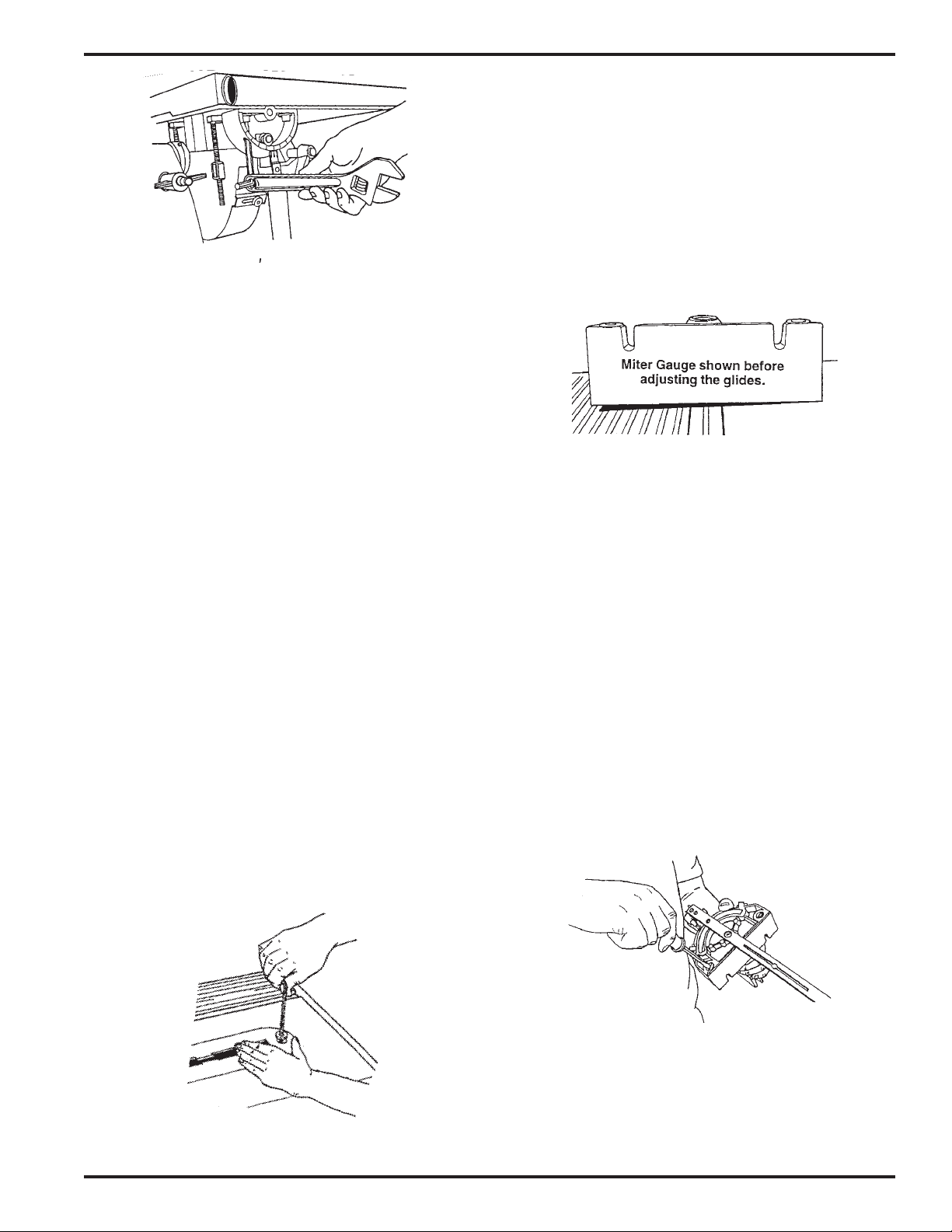
ADJUST THE HEADREST LOCK
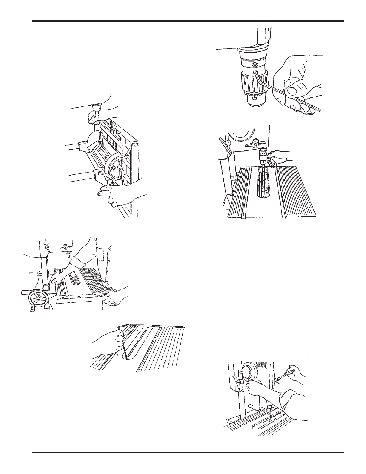
1. To check the headrest lock (15), grasp the way
tubes near the tie bar (25) and pull up, as
demonstrated by the right hand in Figure B-
44.
2. If there is "give" in the lock, unlock the handle
and use a medium Phillips screwdriver to
turn the lock shaft (6) clockwise, as done by
the left hand in Figure B-44. If the lock is
difficult to operate, the shaft is too tight. To
loosen, unlock the handle and turn the shaft
counterclockwise.
SAFETY
WARNING
Make sure the speed dial is set to "Slow", then
turn off and unplug the Mark V before performing
any ALIGNMENT procedure.
1. Complete ALL of the following procedures–
and then recheck them at regular intervals.
You MUST use an accurate combination
square for alignment and adjustment. To
check that your square is accurate, select a
board with at least one straight and true edge.
Place the square against the good edge and
draw a line across the width. Flop the square
over and hold it against the same edge and
draw another line next to the first one. If the
lines are parallel, your square is accurate.
2. All the parts and accessories which support or
guide the stock MUST be aligned parallel
with or perpendicular to the main spindle's
plane of rotation. During the following align-
ment procedures the saw blade (provided in
the accessories box) will represent the main
spindle's plane of rotation.
NOTE
If you have installed casters (optional) on your
Mark V, make sure they are retracted and the legs
on the Mark V sit firmly on a level floor. Do this
now.
Tools Needed:
• 3/16" Allen wrench
• 5/32" Allen wrench, long handle (provided)
• 5/32" Allen wrench, short handle (provided)
• 5/16" Allen wrench (provided)
• 9/16" wrench
• Arbor wrench (provided)
• 1/2" wrench
• Adjustable wrench (optional)
• 1/2" socket and ratchet wrench with short extension
• 3/8" to 1/2" drill bit
• Small Straightblade screwdriver
• Medium Straightblade screwdriver
• Medium Phillips screwdriver
• High quality combination square
Alignment of Model 520
Figure B-44

Mark V Model 520 Alignment
Page 2
ADJUST THE CARRIAGE LOCK
3. If the carriage lock handle (187) does not lock
into the horizontal position or the carriage
moves out of position, the lock needs adjust-
ing. To adjust the lock, use a 1/2" socket with
an extension and ratchet handle to tighten or
loosen the nut located at the back of the
carriage assembly, as shown in Figure B-45.
Figure B-45
4. When the carriage lock handle locks into the
horizontal position and the carriage no longer
moves when the handle is in the horizontal
position, tighten the nut a final 1/4 turn.
WARNING
The carriage lock handle MUST lock into the
horizontal position, otherwise the carriage lock
may vibrate loose.
SET THE WORKTABLE'S 90° LEFT STOP
WARNING
Always make sure the Mark V headstock and
carriage are locked and all casters are raised off
the floor before lifting the Mark V into the vertical
drill press position.
5. Unlock the carriage and headstock. Move the
headstock to the middle of the way tubes.
Then move the carriage between the head-
stock and base mount (right side).
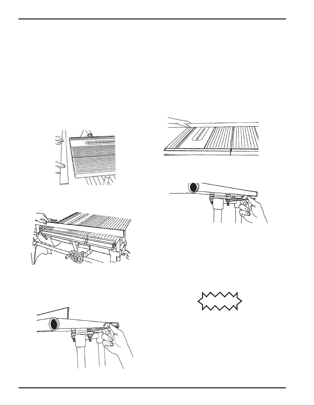
6. Tightentheheadstockandcarriagelocks. Place
the Mark V in the vertical position by loosen-
ing the headrest handle (15), firmly grasping
the way tubes (20) near the headrest end, and
lifting the tubes into the 90° position, as dem-
onstrated in Figure B-46.
Figure B-46
Figure B-47
Figure B-48
7. See Figure B-47. Use your fingers to screw in
the base lock (2). Note the base lock is slightly
off center to the countersink found in the
bench base, as shown in Figure B-48. This
offset allows the base lock to more firmly hold
the base in place.
Alignment Mark V Model 520
Page 3
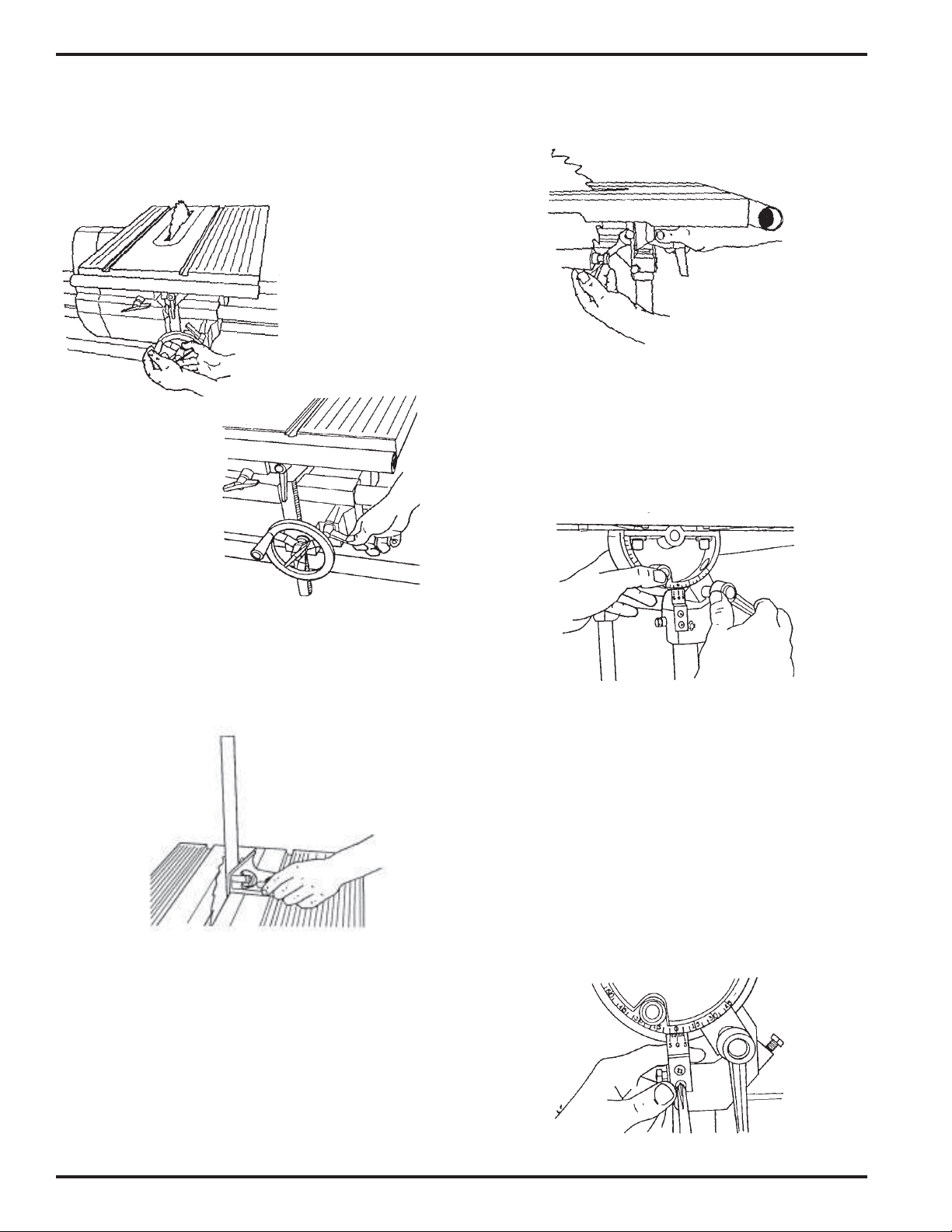
8. Move the worktable into the 90° position by
loosening the table tilt lock (165), as seen in
Figure B-49, then putting the worktable in the
horizontal 90° position, as shown in Figure B-
50. Retighten the table tilt lock only enough to
allow movement with firm pressure.
9. Use a 5/32" Allen wrench to remove the table
insert, as demonstrated in Figure B-51.
Figure B-52
Figure B-54
Figure B-51
Figure B-53
Figure B-49
Figure B-50
10. To install the drill chuck, mount the chuck on
the spindle and align the chuck's set screw
with the spindle knob's set screw, as shown in
Figure B-52. This allows the chuck's set screw
to set on the flat part of the spindle. Use a 5/
32" Allen wrench to securely tighten the drill
chuck's set screw.
11. Install a 3/8" to 1/2" straight drill bit in the
drill chuck and use the chuck key to lock it
place. See Figure B-53.
NOTE
Check the straightness of the drill bit by rolling it on
a flat surface. You can also hand-rotate the drill
chuck while holding the combination square against
the drill bit and the table. If the bit is not straight
DO NOT use it for these alignment instructions.
12. With the drill bit above the table opening, use
the quill feed to extend the bit 1/2" into the
table opening, as in Figure B-54.

Mark V Model 520 Alignment
Page 4
15. Recheck the setting by loosening the tilt lock,
moving the table, and then repeating Steps 13
and 14. (Rechecking the settings is very im-
portant!)
SET THE WORKTABLE'S 0° STOPSET THE WORKTABLE'S 0° STOP
SET THE WORKTABLE'S 0° STOPSET THE WORKTABLE'S 0° STOP
SET THE WORKTABLE'S 0° STOP
16. Remove the drill bit and drill chuck from the
spindle.
17. Loosen the base lock (2). Firmly grasp the way
tubes and lower the headstock into the hori-
zontal position, then engage the head rest.
18. Loosen the table tilt lock and place the table in
the horizontal "0" position. Retighten the table
tilt lock only enough to allow movement with
firm pressure.
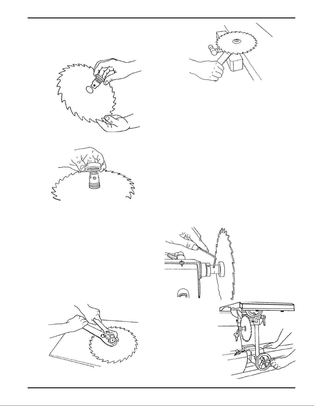
19. Mount the saw blade on the arbor:
a. Remove the arbor nut by turning it clock-
wise, as seen in Figure B-59a. Hold the
arbor with the threaded part pointing to
the left.
13. Set the combination square against the bit and
table, as shown in Figure B-55. The square
should contact the bit along its entire length.
When the table is exactly perpendicular to the
drill bit, lock the table, as seen in Figure B-56.
Figure B-56
Figure B-55
14. Both 90° stops (shown in Figs. B-57 and B-58)
should contact the underside of the table. If
they don't, use a 1/2" wrench to adjust the
stops.
Figure B-59a
Figure B-58
Figure B-57
Alignment Mark V Model 520
Page 5
b. Hold the blade with the teeth pointing
toward you, as shown in Figure B-59b,
then insert the arbor through the hole.
Replace the nut and finger tighten it, as in
Figure B-59c.
Figure B-59e
Figure B-59d
Figure B-59c
Figure B-59b
c. Place the blade and arbor on your work-
bench with the nut pointing up.
d. Hold the arbor with an adjustable wrench
and tighten the arbor nut with the arbor
wrench, as demonstrated in Figure B-59d.
Another way to tighten the arbor nut is to
clamp the arbor in a bench vise, as illus-
trated in Figure B-59e, and tighten the nut
with the arbor wrench.
NOTE
The only time the saw blade is used without the
upper or lower saw guards is during alignment and
only after the Mark V is turned off and unplugged.
20. Mount the saw blade on the spindle and align
the arbor set screw with the spindle knob's set
screw,thenuse a 5/32"Allen wrench to tighten
the arbor set screw, as seen in Figure B-60.
21. Reinstall the table insert (138) in the work-
table.
22. Raise the worktable so that it clears the top of
the saw blade.
23. Loosen the carriage lock and slide the carriage
so the saw blade is directly beneath the slot in
the table insert. See Figure B-61.
Figure B-60
Figure B-61
Mark V Model 520 Alignment
Page 6
24. Lower the worktable (but not all the way
down) so the saw blade comes through the
slot. Lock the table height, as seen in Figure B-
62.
25. Tighten the carriage lock, as shown in Figure
B-63.
Figure B-62
Figure B-63
Figure B-66
Figure B-65
Figure B-67
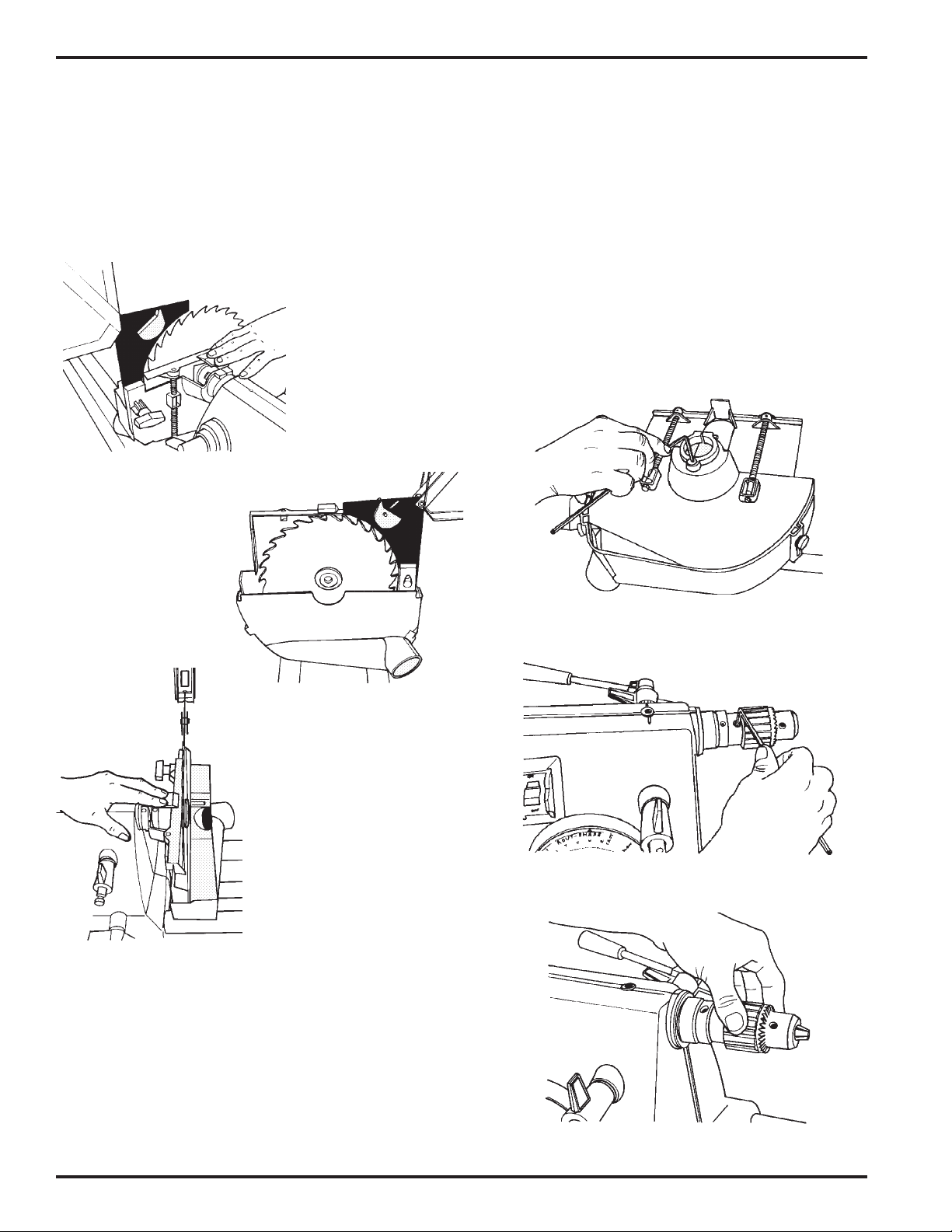
26. Place the combination square against both the
saw blade and worktable, as seen in Figure B-
64. Make sure the square's blade does not
touch a saw tooth and does rest in a gullet
between teeth.
bolt is adjusted, the stop pin will "lock" back
when the tilt lock is tightened. See Figure B-
65.
29. Loosen the tilt lock, move the worktable, then
depress the 0° stop pin until the stop bolt
contacts it. Tighten the tilt lock, and recheck
the setting by repeating Steps 26 through 28.
See Figure B-66. (It is very important to re-
check the setting!)
ADJUST THE TABLE TILT INDICATOR
30. Tighten the table tilt lock and check that the "0"
mark on the indicator aligns with the "0" mark
on the trunnion ((149).
31. To adjust the scale, use a medium Phillips
screwdriver to loosen the two screws which
hold the indicator to the tie bar. See Figure B-
67. Then while holding the indicator in posi-
tion so the "0"s are aligned, retighten the
screws.
Figure B-64
27. If the worktable is not exactly perpendicular
to the saw blade, adjust the worktable so it is
perpendicular to the saw blade, then tighten
the tilt lock.
28. To adjust the 0° stop, simultaneously depress
the table stop pin and use a 1/2" wrench to
adjust the stop bolt. The stop bolt should just
contact the side of the stop pin. Once the stop
Alignment Mark V Model 520
Page 7
ADJUST THE WORKTABLE'S 45°
STOPS
32. Loosen the table height lock and raise the table
until it clears the saw blade. Tighten the
height lock.
33. Loosen the tilt lock and tilt the worktable to
the right until it makes contact with the two
45° stop bolts (158).
34. Tighten the tilt lock only enough to allow
movement with firm pressure.
35. Loosen the quill feed (shown in Figure B-68)
and extend the quill so the saw blade is cen-
tered beneath the slot in the table insert. When
it is centered, lock the quill feed.
36. Lower the worktable so the saw blade extends
through the slot. See Figure B-69. Lock the
table height.
38. If the worktable is not exactly 45° to the saw
blade, adjust the worktable so it is.
39. Tighten the tilt lock, then use a 1/2" wrench to
adjust the 45° stop on the front side of the
worktable (shown in Figure B-71) and the
back side of the worktable (shown in Figure B-
72). The stops should just contact the under-
side of the table.
40. Loosen the tilt lock and move the table. To
recheck the 45° stops, repeat Steps 35 through
39. (It is very important to recheck the set-
ting!)
Figure B-68
Figure B-70
Figure B-69
Figure B-71
Figure B-72
37. Removethebladefromthecombinationsquare
and place the square against the saw blade
and the worktable, as shown in Figure B-70.
Make sure the combination square doesn't
rest on the table insert.

Mark V Model 520 Alignment
Page 8
ALIGN THE MITER GAUGE SLOTS
41. Return the worktable to the horizontal "0"
stop and tighten the tilt lock. The carriage lock
and headstock lock should also be tightened.
Remove the table insert.
42. Place the miter gauge in the right miter gauge
slot, and use a 5/32" Allen wrench to remove
the quick clamp from the safety grip, as shown
in Figure B-73.
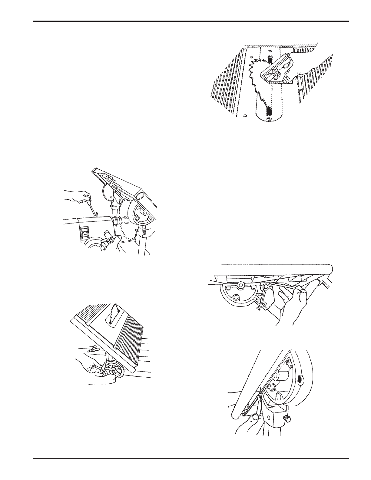
45. If the miter slots need to be aligned, do the
following:
a. Tilt the table to 45° and tighten the tilt lock.
b. Use a 5/16" Allen wrench to loosen all four
bolts (147) which hold the worktable to the
trunnions, as pointed out in Figure B-77.
Loosen the bolts only enough to allow
movement with firm pressure. See Figure
B-78.
Figure B-74
Figure B-73
43. Insert the long 5/32" Allen wrench through
the miter gauge. Borrow a set screw from the
lathe tool rest and use the short 5/32" Allen
wrench to install it in either top miter gauge
hole, as seen in Figure B-74. Place the tip of the
long wrench against the front side of the saw
blade and tighten the set screw.
44. Move the miter gauge from front to back
along the saw blade, as shown in Figs. B-75
and B-76. If it hangs up on the blade or a gap
develops, the miter gauge slots need to be
aligned. Make sure the Allen wrench does not
contact a saw blade tooth, because the tooth
"set" will cause misalignment.
Figure B-76
Figure B-78
Figure B-75
Figure B-77
NOTE
If you find it difficult to loosen the bolts, consider
using a T-handle Allen wrench, or use a boxed
wrench for extra torque. Another alternative is to
use the hanging hole in an adjustable wrench, as
demonstrated in Figure B-78a.
Alignment Mark V Model 520
Page 9
47. First tighten the rear screw. Then the front of
the insert will be sprung slightly above the
table. Level the insert by placing your hand on
the front of the insert, as in Figure B-79, and
slowly turning the front screw until it draws
the front of the insert flush with the worktable
surface.
ADJUST THE MITER GAUGE GLIDES
48. Place the miter gauge in the worktable's miter
gauge slot. See Figure B-80.
Figure B-78a
c. Position the worktable back to the hori-
zontal "0" and tighten the tilt lock.
d. Adjust the worktable, then again move the
miter gauge and wrench along the face of
the saw blade until the wrench tip consis-
tently contacts the entire blade surface.
e. When the miter gauge slot is aligned, use
the 5/16" Allen wrench to retighten the
two trunnion bolts which are closer to the
headstock. Then loosen the table tilt lock,
tilt the worktable to 45°, and retighten the
table tilt lock. Use the 5/16" Allen wrench
to retighten the other two trunnion bolts.
f. Loosen the table tilt lock and move the
table, then return it to the horizontal "0"
position. Recheck the slot alignment. If it
is off, repeat Steps dand e.
NOTE
Tighten the bolts only after the table tilt lock is secured.
Otherwise the worktable will bow or bind the next time
the table tilt lock is tightened.
INSTALL THE TABLE INSERT IN THE
WORKTABLE
46. Place the table insert in the worktable recess.
Use a 5/32" Allen wrench to start both screws.
Figure B-79
Figure B-80
49. Check to see if the miter gauge wobbles side-
to-side. Also, slide it back and forth in the slot
to check if the miter gauge scrapes against the
table. If the miter gauge rocks or scrapes the
table, adjust the glides.
50. If the glides need to be adjusted, do the follow-
ing:
a. Remove the miter gauge from the slot and
turn it over.
b. Use a medium screwdriver to screw the
glides in or out, as illustrated in Figure B-
81, so that the glides hold the miter gauge
1/64" to 1/32" off the worktable and the
miter gauge does not rock in the slots.
Figure B-81
c. Return the miter gauge to the slot and
recheck and re-adjust it, if needed.

Mark V Model 520 Alignment
Page 10
ADJUST THE MITER GAUGE FACE
51. Remove the safety grip from the miter gauge.
Make sure you keep the small, thin washer.
52. Put the miter gauge in the right slot and place
the combination square against the saw blade
and miter gauge face, as seen in Figure B-82.
Figure B-83
Figure B-84
Figure B-82
53. If the miter gauge face is not perpendicular to
the saw blade, do the following:
a. Use a long Allen wrench to loosen the lock
knob (268) and adjust the miter gauge so it
is perpendicular to the saw blade, then
tighten the lock knob. See Figure B-83.
b. Use a medium screwdriver, loosen the
screw(273) whichholds the indicator plate
(275 ), and set its "0" to the miter gauge's
"90". Tighten the screw. See Figure B-84.
55. Depress the plunger, then turn the stop screw
until you feel it touch the plunger.
56. To re-check the stop setting, repeat Steps 52
through 55.
ADJUST BOTH 45° STOPS
57. Loosen the lock knob (268) and pull out the
plunger. Then, at the same time, rotate the
miter gauge and push in the plunger until it
hits the 45° stop (there is one on each side of
the 90° stop).
58. Use a combination square to set the miter
gauge face at 45° to the saw blade. If the 45°
stop needs adjustment, use a medium screw-
driver to back out the 45° screw 2 to 3 turns.
59. Depress the plunger, then turn the stop screw
until you feel it touch the plunger.
60. To recheck the stop setting, repeat Steps 54
through 59.
61. To adjust the other 45° stop, repeat Steps 57
through 60.
REMOVE THE SAW BLADE
62. Loosen the table height lock and raise the table
so that it clears the saw blade, then tighten the
lock. Unlock the carriage lock and move the
worktable to the right.
Figure B-85
Figure B-86
ADJUST THE 90° POSITIVE STOP
54 Use a small screwdriver to back out the 90°
stop screw 2 to 3 turns, as shown in Figure B-
85.
63. Use the 5/32" Allen
wrench to loosen the
arbor set screw. Re-
move the saw blade.
See Figure B-86.
64. Unlock the table height
lockandlowerthe table
to a comfortable work-
ing height. Tighten the
lock.

Page 11
Alignment Mark V Model 520
Figure B-99
ALIGN THE EXTENSION TABLE
NOTE
These instructions are for aligning the exten-
sion table on the right side of the headstock. You
70. The worktable should already be mounted
in the carriage mount. Move the worktable
next to the extension table and adjust it to
about 1/4" above the extension table, as
seen in Figure B-100.
ALIGN THE PRO FENCE PARALLEL
WITH THE WORKTABLE
63. Place the miter gauge in the left slot of the
worktable on the infeed side. Place the Pro
Fence on the right side of the saw table.
64. Insert the long 5/32" Allen wrench through
the miter gauge and secure it using the short
5/32" Allen wrench and a set screw bor-
rowed from the tool rest.
65. Move the fence toward the Allen wrench
until it just touches it.
66. Lock the lower fence lock handle first, then
lock the upper fence lock handle to secure
both ends of the pro fence.
67. Slide the miter gauge back and forth in the
slot. The tip of the Allen wrench should
keep in slight contact with the fence. Watch
that you don't scratch the fence.
68. If the allen wrench pulls away from or binds
against the fence, the fence needs aligning. If
so, do the following:
a. Using the short 5/32” short Allen
wrench, loosen the four button head
cap screws (3), located on the top of the
fence, slightly. They should be just tight
enough to require firm pressure to align
the fence.
b. Raise the upper fence lock handle only
to unlock the rear of the fence.
c. Adjust the rear end of the fence so that
it just touches the allen wrench as the
miter guage slides along the fence.
d. When alignment is reached, lock the
upper fence lock handle. Slide the miter
gauge back and forth to double check
your alignment. Using the short 5/32”
Allen wrench, tighten the four button
head cap screws (3) completely.
can also follow these same procedures to align it
to the left side of the headstock.
For most projects, align the extension table on
the right side, since it can usually be used when
placed on the left side. However, once the exten-
sion table is aligned on the right side, it cannot
be transferred to the left side and still maintain
precise alignment.
If you wish precise alignment on the left side,
repeat the following instructions– but place the
extension table on the left side in the headstock.
69. Mount the extension table in the Mark V's
accessory base mount (on the right side) at a
comfortable height, as shown in Figure B-
99. Use a 1/2" wrench to loosen the bottom
nuts holding the table base to the table ap-
proximately 1/4" from the table. This will
allow you room for later adjustment.
Figure B-100
Page 12
Mark V Model 520 Alignment
71. Hold a straightedge against the infeed edge
of both the worktable and extension table
tubes, as in Figure B-101. Line up the exten-
sion table's infeed edge with the worktable's
infeed edge. The elongated holes in the ex-
tension table's base permit you to slide the
extension table forward and backward.
72. Hold a straightedge on the infeed top sur-
face of both the worktable and the extension
table, as shown in Figure B-102. As needed,
adjust the top nuts located on the infeed side
of the extension table, in order for the
straightedgetobelevelacross both the work-
table and the extension table infeed sides.
See Figure B-102a.
Figure 103a.
Figure B-102
Figure B-101
Figure B-103
Figure B-102a
73. Hold the straightedge on the outfeed top
surface of both the worktable and the exten-
siontable,asseeninFigureB-103. Asneeded,
adjust the top nuts located on the outfeed
side of the extension table, in order for the
straightedgetobe level across both thework-
table and the extension table outfeed sides.
74. Double check the levelness at the infeed and
outfeed sides of the table surfaces. All four
top nuts (those nearest the table) used in
levelingthe extension tableshould be touch-
ing the base.
75. When the tables are aligned on three sides–
infeed side edge (along the table tubes, as in
Figure B-101), infeed top surface (as in Fig-
ure B-102), and outfeed top surface (as in
Figure B-103) – securely tighten the bottom
nut on each of the four studs, as seen in
Figure 103a.
CAUTION
DO NOT overtighten the nuts. Tighten the nuts until
they bottom out, then no more than 1/8 additional turn.
Overtightening the nuts will stretch and damage the
threads.
NOTE
If you move the Mark V to another location–
especially one with an uneven floor– remember
to re-check the extension table alignment.

Page 13
Alignment Mark V Model 520
Figure B-104
Figure B-108
Figure B-106
Keps Nuts
Figure B-105
Figure B-107
ALIGN THE EXTENSION
TABLE TUBES
76. Place the straightedge along the infeed-side
tops of both the worktable and extension
table tubes, as shown in Figure B-104.
77. If the extension table's tube is not aligned
withtheworktable'stube,usea7/16"wrench
to slightly loosen both keps nuts (248) at-
tachingthe tube tothe extension table. Make
the needed adjustments, then re-tighten the
nuts. See Figure B-105.
78. Repeat Steps 85 and 86 for the extension
table's tube located on the outfeed-side.
MOUNT THE SAW GUARD
79. Loosen the accessory mount lock and re-
move the extension table. Loosen the table
heightlock and removethe worktable. Place
the saw blade and arbor in the lower saw
guard cover (204).
80. Fit the lower saw guard's clamp on the
spindle quill (59). Line up the arbor set
screw with the spindle knob's set screw
(where the spindle flat is located). Use a 5/
32" Allen wrench to tighten the arbor set
screw, as shown in Figure B-106.
87. Use the 5/32" Allen wrench to tighten the
socket head screw (215) on the saw guard
collar, as seen in Figure B-107.
INSTALL THE RIVING KNIFE
82. Loosen the guard lock knob (210) and insert
the upper saw guard's riving knife (199)
between the guard (213) and the lock plate
(208), as demonstrated in Figure B-108.
Page 14
Mark V Model 520 Alignment
Figure B-112
Figure B-111
Figure B-113
Figure B-114
Figure B-110
Figure B-109
83. Make sure the riving knife is fully seated
between the guard and the lock plate, as in
Figure B-109. The curved portion of the
riving knife should be very close to the saw
blade teeth (about 1/8"), as illustrated in
Figure B-110. Tighten the guard lock knob
(210). Look to see if the riving knife is
centered with the saw blade, as shown in
Figure B-111.
84. If the riving knife is not centered with the
saw blade, follow these steps:
a. Notice which way the riving knife is
not centered with the saw blade.
b. Unclamp and remove the upper saw
guard, then remove the saw blade and
lower saw guard.
c. Use a 5/32" Allen wrench to adjust the
stopscrew(211) located below the lower
saw guard's collar, see Figure B-112.
• If the riving knife is to the left of the
saw blade, back out the stop screw
(counter-clockwise).
• If the riving knife is to the right of the
saw blade, screw in the stop screw
(clockwise).
d. Re-install the saw blade, lower saw
guard and riving knife, according to
Steps 88 through 92. If the riving knife
is still not centered on the saw blade,
repeat this Step 93.

Page 15
Alignment Mark V Model 520
Figure B-118
Figure B-117
Figure B-116
Figure B-115
ALIGN THE LATHE CENTERS
85. Remove the saw guards and the saw blade,
thenloosenthecarriage and headstock locks.
Move the headstock and carriage all the way
to the right and lock them in place.
86. Mount the drill chuck on the spindle, as
shown in Figure B-113. Completely close
the chuck jaws, as in Figure B-114.
87. Mount the cup center into the tailstock's
adjustable center, as seen in Figure B-115,
thenmount thetailstock into the base mount
(right side). Tighten the mount lock.
88. Loosen the quill lock. Extend the quill (seen
in Figure B-116), so the drill chuck almost
touches the cup center point and the center
point could fit into the chuck jaws.
89. If the center point does not "fit" into the
chuck jaws, determine whether you need to
adjustthecupcenter point horizontally and/
or vertically. Then do the following:
a. To adjust the cup center point horizon-
tally, loosen the set screw that locks the
adjustable center, as seen in Figure B-
117. Rotate the adjustable center as
needed to line up the cup center with
the drill chuck, then tighten the set
screw.
b. To adjust the cup center point verti-
cally, loosen the mount lock, then
loosen the tailstock stop collars. Raise
or lower the tailstock in the base mount
until the cup center point vertically
lines up with the drill chuck, then
tighten the mount lock. Press the stop
collars down firmly against the base
mountandtighten the collarsetscrews,
as shown in Figure B-118.
Popular Tools manuals by other brands

Gardena
Gardena 8022 operating instructions

SIXTOL
SIXTOL HOME PINK 120 BAG instruction manual

Beta
Beta 665 Operation manual and instructions

HOZAN
HOZAN C-438 quick start guide

Current Tools
Current Tools 509 Operating, Safety and Parts Manual

Pittsburgh Automotive
Pittsburgh Automotive 63984 Owner's manual & safety instructions


