Shopsmith MARK V Instructions for use
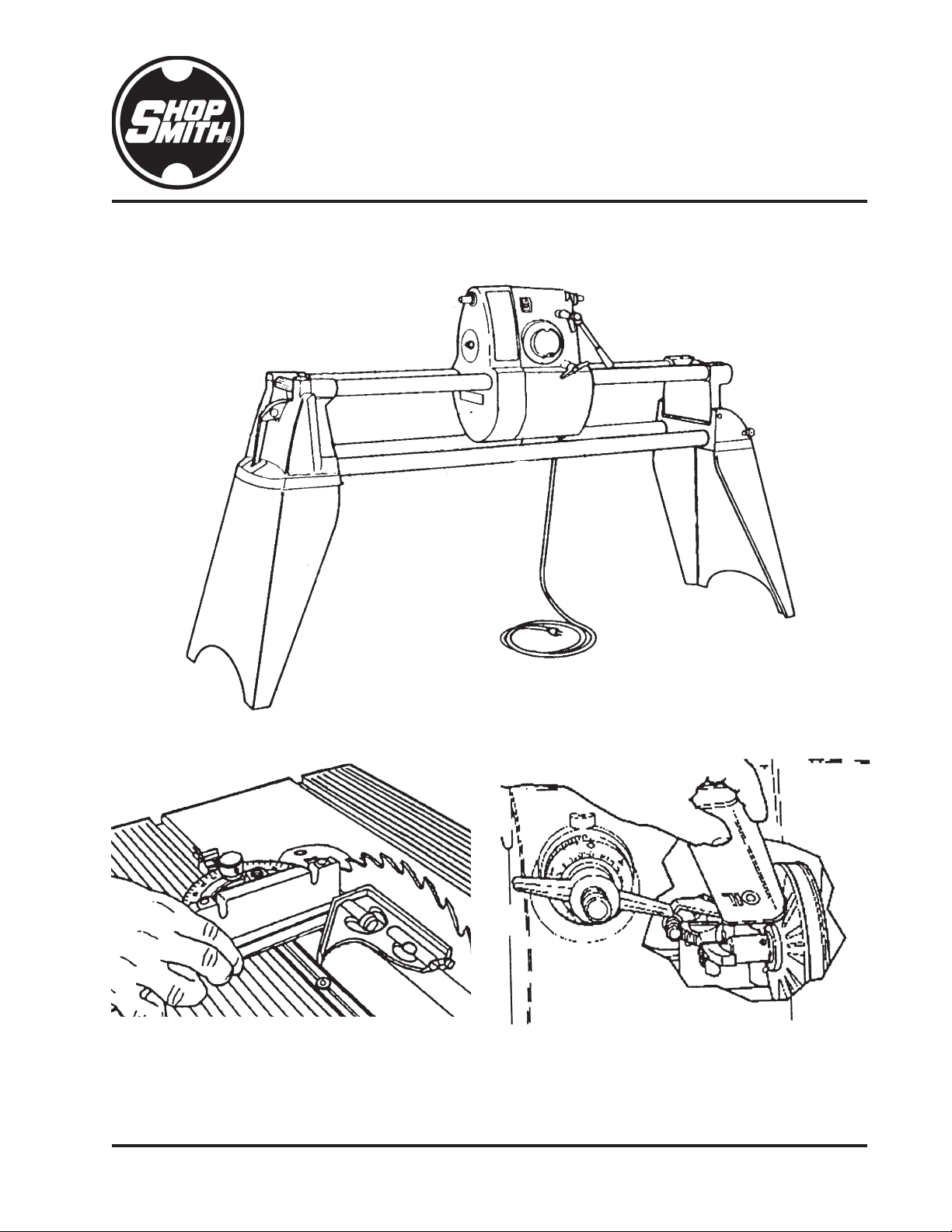
MARK V
ALIGNMENT & MAINTENANCE

SHOPSMITH MARK V 845180
Page 2
NOMENCLATURE
The Shopsmith MARK V will perform all the
functions of a Table Saw, Disc Sander, Drill
Press, Horizontal Boring Machine, and Wood
Lathe.
Basically, the MARK V is a rigid Bench that
holds the Headstock and a Worktable System.
The upper part of this Bench can be positioned
horizontally or vertically. The Headstock and
the Worktable slide independently and are
positioned along the Upper or Way Tubes.
You can mount Accessories to the Headstock
and operate them at different speeds. The
Worktable can be positioned over, under or
beside these accessories to hold stock at vari-
ous angles. In this way, the Bench, Headstock,
Worktable, and Accessories combine to make
a unique, capable and versatile Woodwork-
ing System.
Before you proceed, familiarize yourself with
the MARK V's basic parts:
1. Legs - SupporttheWayTubesandBench
Tubes.
2. Headrest Lock - Secures the MARK V in
the horizontal position.
3. Accessory Mount Locks - Secures the
Extension Table, Major Accessories, and
the Lathe Tailstock.
4. Power Mount - Holds the Extension
Table and the Major Accessories.
5. Way Tube Tie Bar - Holds the free end of
the Way Tubes.
6. Way Tubes - Supports the Headstock
and Carriage and allows them to slide.
7. Auxiliary Spindles - The Upper Spindle
provides power to the Bandsaw, Belt
Sander, Strip Sander and Thickness
Planer. The Lower Spindle provides
power to the Jointer and Scroll Saw.
8. Logo Cover - Provides access to the wir-
ing and Speed Changer Mechanism.
Used for maintenance access. (Hidden
from view)
9. Power Switch - Turns the MARK V on
and off. Has a removable Safety Key on
newer MARK V’s or is a Toggle Switch
on older units.
10. Quill Lock - Secures the Quill in posi-
tion.
11. Quill Feed Stop - Stops the Quill at
predetermined distances out from the
1
2
3
4
5
20
19
7
89
18
17
16
15
14
13
10 11
12
21
6
22
RIGHT
SIDE
LEFT
SIDE

Page 3
845180 SHOPSMITH MARK V
Headstock. (Hidden from view)
12. Quill - Contains the Main Spindle &
Spindle Bearings.
13. Main Spindle - Mounts the Saw Blades,
Sanding Discs, and other Accessories.
14. Quill Feed Lever - Extends the Quill out
from the Headstock.
15. Base Mount - Holds the Extension Table
and Lathe Tailstock.
16. Base - Allows the Way Tubes to pivot to
either a horizontal or vertical position.
17. Base Lock - Secures the MARK V in the
vertical position.
18. Headstock Lock - Secures the Head-
stock on the Way Tubes.
19. Speed Dial - Controls the speed of the
MainandAuxiliarySpindles.ONLY turn
the speed dial when the MARK V is
running. Otherwise, you will damage
the speed changing mechanism. Turn
the speed dial to "Slow" after every op-
eration and then turn MARK V off.
20. Bench Tubes - Holds the MARK V rigid.
21. Headrest - Holds the Way Tube Tie Bar.
22. Belt Cover - Allows access to the Belts
and Sheaves.
MARK V MODEL 500
23. Extension Table - Mounts in either the
34
35
23
25
24 27
26
28 29
30
31
32
33
36
Power Mount or the Base Mount to pro-
vide extra support for the stock.
24. Rip Fence - Mounts to the Table and is
used as a guide, support or stop. It auto-
matically aligns itself parallel to the
Blade. Holes in the Fence are used to
mount fixtures and fence extensions.
25. Miter Gauge Slots - Guide and secure
the Miter Gauge.
26. Table Insert - Used for sawing, sanding,
drilling and boring. It can be replaced
with inserts for dadoing, molding, drum
sanding and shaping.
27. 10" Saw Blade - Mounts to the 1-1/4"
Arbor which then mounts to the Main
Spindle. This Saw Blade is use for both
crosscutting and ripping.
28. Upper Saw Guard - Provides a physical
barrier between you and the part of the
Blade above the Table. An anti-kickback
mechanism helps control kickbacks.
29. Miter Gauge with Safety Grip - Holds
stock firmly at various angles. It slides
freely or locks in the Miter Gauge Slots.
30. Worktable - Holds the stock and pro-
vides a working surface.
31. Lower Saw Guard - Protects you from
the part of the Blade or cutter below the
Table.
32. TableSupport Tubes -Supportthe Table
above the Bench. Each tube has racks
that mesh with Pinions in the Carriage to
raise and lower the Table.
33. Carriage - Slides along the Way Tubes
and holds the Table Support Tubes and
the Lathe Tool Rest.
34. Carriage Lock - Secures the Carriage on
the Way Tubes.
35. Table Height Handle - Turns the Pin-
ions in the Carriage which raise and
lower the Table.

SHOPSMITH MARK V 845180
Page 4
36. Table Height Lock - Secures the Table at
any height.
37. Trunnions - Allows the Table to tilt up to
90° Left and 45° Right.
38. Table Tilt Indicator - This Vernier Scale
indicates the Table angle.
39. Table Tilt Lock - Secures the Table at
any angle, up to 90° Left and 45° Right.
40. Table Tie Bar - Supports the Table Sup-
port Tubes and the Trunnions.
41. Table Stops - When properly adjusted,
they stop the Table at 90° Left, 45° Right
and 0°. (Note: one of the two 90° Table
Stop Bolts is shown.)
MARK V MODELS 510 & 520
37
40
38
39
41
42 43 44
54 53
45
52
51
50
46 48
47
49
42. Extension Table - Mounts in either the
Power Mount or the Base Mount to pro-
vide extra support for the stock.
43. Miter Gauge Slots - Guide and secure
the Miter Gauge.
44. Rip Fence - Mounts to the Table and is
used as a guide, support or stop. It auto-
matically aligns itself parallel to the
Blade. Holes in the Fence are used to
mount fixtures and fence extensions.
45. Table Insert - Used for sawing, sanding,
drilling and boring. It can be replaced
with inserts for dadoing, molding, drum
sanding and shaping.
46. 10" Saw Blade - Mounts to the 1-1/4"
Arbor which then mounts to the Main
Spindle. This Saw Blade is use for both
crosscutting and ripping.
47. Upper Saw Guard - Provides a physical
barrier between you and the part of the
Blade above the Table. An anti-kickback
mechanism helps control kickbacks.
48. Miter Gauge with Safety Grip - Holds
stock firmly at various angles. It slides
freely or locks in the Miter Gauge Slots.
49. Worktable - Holds the stock and pro-
vides a working surface.
50. Lower Saw Guard - Protects you from
the part of the Blade or cutter below the
Table. The Saw Guard has a Dust Chute.
The Lower Saw Guard is also used with
the Sanding Disc.
51. TableSupport Tubes -Supportthe Table
above the Bench. Each tube has racks
that mesh with Pinions in the Carriage to
raise and lower the Table.
52. Carriage - Slides along the Way Tubes
and holds the Table Support Tubes and
the Lathe Tool Rest.
53. Carriage Lock - Secures the Carriage on
the Way Tubes.
54. Table Height Lock - Secures the Table at
any height.

Page 5
845180 SHOPSMITH MARK V
Place the Square against the good edge and
draw a line across the width. Flop the Square
over and hold it against the same edge and
draw another line next to the first one. If the
lines are parallel, your Square is accurate.
TOOLS NEEDED:
This list covers all tools required for all mod-
els. Some tools listed may not be necessary for
your Model MARK V.
3/16" Allen Wrench
5/32" Allen Wrench, Long Handle
5/32" Allen Wrench, Short Handle
5/16" Allen Wrench
9/16" Wrench
Arbor Wrench
1/2" Wrench
Adjustable Wrench
1/2" Socket
Socket Wrench with Short Extension
1/2" Drill Bit
Small Straight Blade Screwdriver
Medium Straight Blade Screwdriver
Medium #12 Phillips Screwdriver
Large #3 Phillips Screwdriver
High Quality Combination Square
All the parts and accessories which support or
guide the stock MUST be aligned parallel
with or perpendicular to the Main Spindle's
plane of rotation. During the following align-
ment procedures the Saw Blade will represent
the Main Spindle's plane of rotation. This is
the only time the Saw Blade is used without
the Upper or Lower Saw Guards and then
only after the MARK V is turned off and
unplugged.
NOTE
If there are Casters installed on your MARK V,
make sure they are retracted and the Legs on the
MARK V sit firmly on a level floor. Check this
58
60
59
55
56
57
55. Trunnions - Allows the Table to tilt up to
90° Left and 45° Right.
56. Table Tilt Indicator - This Vernier Scale
indicates the Table angle.
57. Table Tilt Lock - Secures the Table at
any angle, up to 90° Left and 45° Right.
58. Table Height Crank - Turns the Pinions
in the Carriage which raise and lower
the Table.
59. Table Tie Bar - Supports the Table Sup-
port Tubes and the Trunnions.
60. Table Stops - When properly adjusted,
these Bolts stop the Table at 90° Left, 45°
Right and 0°. (Note: Only the two 90°
Table Stop Bolts are shown.)
WARNING
Make sure the Speed Dial is set to
"Slow", then turn off and unplug the
MARKVbeforeperforminganyALIGN-
MENT procedure.
Complete ALL of the following procedures -
and then recheck them at regular intervals.
You MUST use an accurate Combination
Square for alignment and adjustment. To
check that your Square is accurate, select a
board with at least one straight and true edge.

SHOPSMITH MARK V 845180
Page 6
now.
Also, remember that your MARK V could possibly
go out of alignment if it is moved to an area with
varying floor levelness. Remember to recheck
alignment and make needed adjustments after
moving your MARK V, if needed.
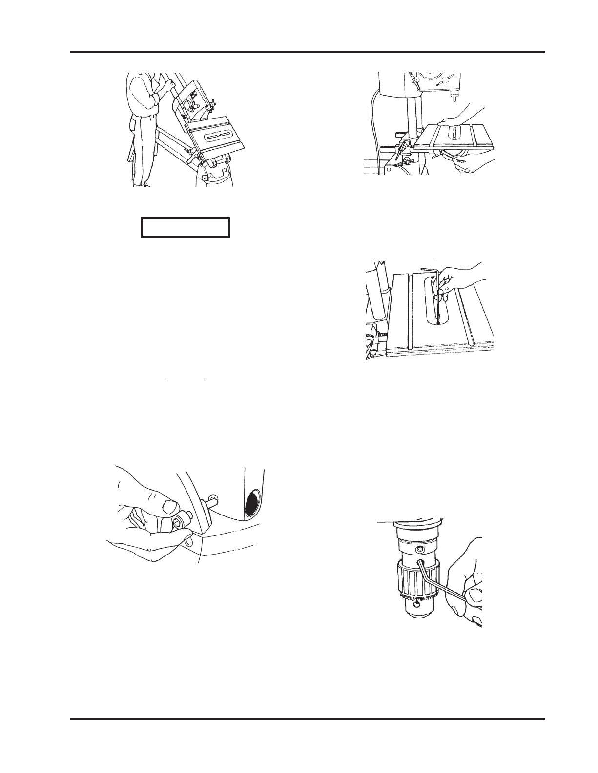
ADJUST THE HEADREST LOCK
(ALL MARK V MODELS)
1. To check the Headrest Lock, grasp the
Way Tubes near the Tie Bar and pull up,
as demonstrated by the Right Hand in
Figure 1.
2. If there is "give" in the Lock, unlock the
Handle and use Medium Straight Blade
Screwdriver to turn the Lock Shaft clock-
wise, as done by the Left Hand in Figure
1. If the Lock is difficult to operate, the
Lock Shaft is too tight. To loosen, unlock
theHandleandturn the Lock Shaft coun-
terclockwise.
Figure 1
ADJUST THE CARRIAGE LOCK
(MARK V MODELS 510 & 520)
1. If the Carriage Lock Handle does not
lock past the horizontal position to four-
o’clock or the Carriage moves when the
lock handle is in this position, the Lock
needs adjusting. To adjust the Lock, use
a 1/2" Socket with an Extension and
Ratchet Handle to tighten or loosen the
Nut located at the back of the Carriage
Assembly, as shown in Figure 2.
Figure 2
2. When the Carriage Lock Handle locks
past the horizontal position to four-
o’clockand the Carriage nolonger moves
when the Handle is in this position,
tighten the Nut a final 1/4 turn.
WARNING
TheCarriageLockHandleMUSTlock
past the horizontal position to Four-
O’clock,otherwisetheCarriageLock
will vibrate loose.
SET WORKTABLE'S 90° LEFT STOP
(MARK V MODEL 500)
1. Unlock the Carriage and Headstock.
Move the Headstock to the middle of the
Way Tubes. Then move the Carriage
between the Headstock and Base Mount
(right side).
2. Tighten the Headstock and Carriage
Locks. Place the MARK V in the vertical
position by loosening the Headrest
Handle, firmly grasping the Way Tubes
near the Headrest end, and lifting the
Tubes into the 90° position, as demon-
strated in Figure 3.
Page 7
845180 SHOPSMITH MARK V
Figure 3
WARNING
AlwaysmakesuretheMARKVHead-
stockandCarriagearelockedandall
Castersareraisedoffthefloorbefore
lifting the MARK V into the vertical
Drill Press position.
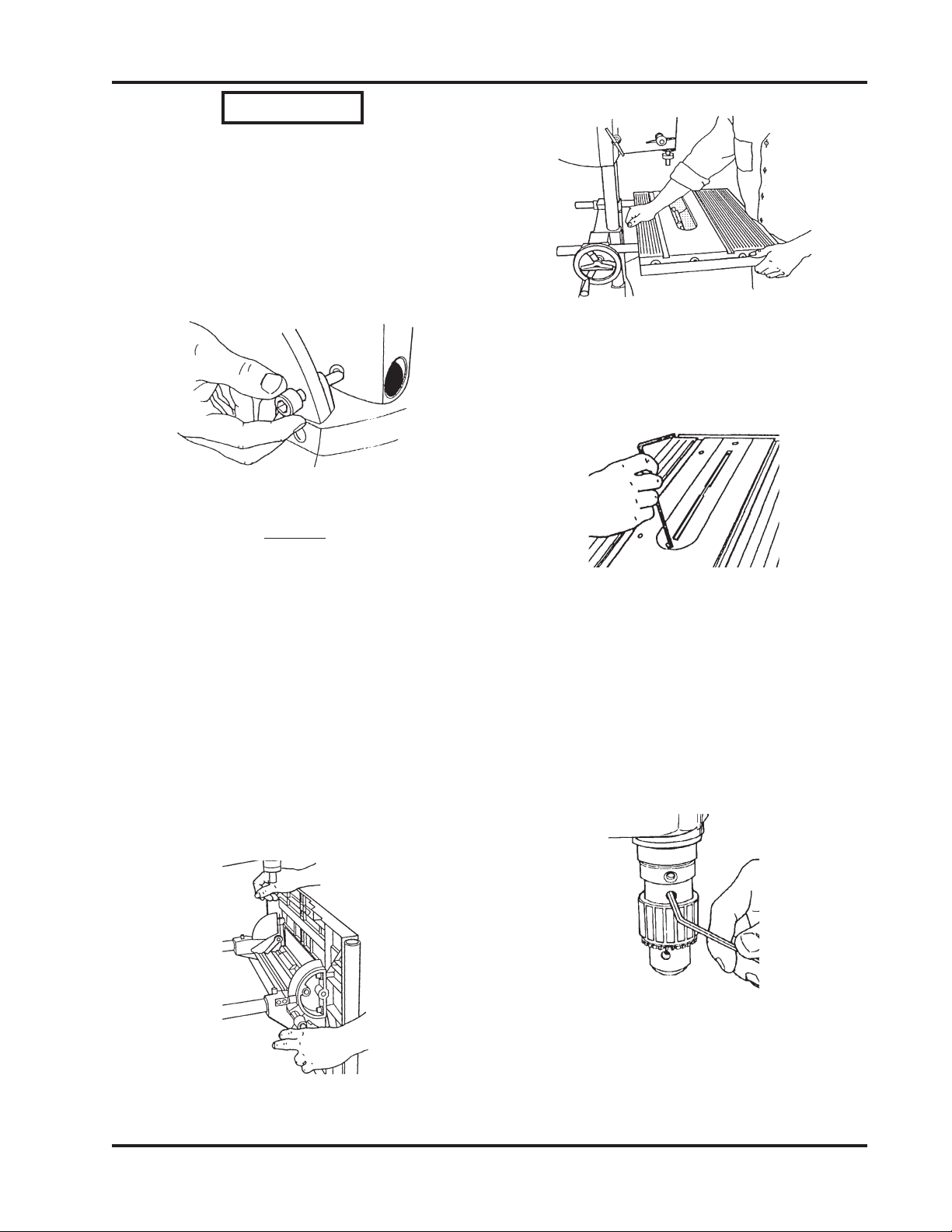
3. Useyourfingers to tighten the Base Lock.
NOTE
The Base Lock is slightly off center to the counter-
sink found in the Base, as shown in Figure 4. This
offset allows the Base Lock to more firmly hold the
Base Arm in place.
Figure 4
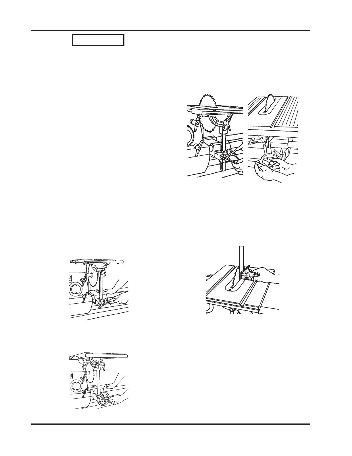
4. Move the Worktable into the 90° posi-
tion by loosening the Table Tilt Lock,
then putting the Worktable in the hori-
zontal 90° position, as shown in Figure 5.
Retightenthe TableTilt Lockonly enough
to allow movement with firm pressure.
Figure 5
5. Use a 5/32" Allen Wrench to remove the
Table Insert, as demonstrated in Figure
6.
Figure 6
6. To install the Drill Chuck, mount the
Chuck on the Spindle and align the
Chuck's Set Screw with the Spindle
Knob's Set Screw, as shown in Figure 7.
This allows the Chuck's Set Screw to set
on the flat part of the Spindle. Use a
5/32" Allen Wrench to securely tighten
the Drill Chuck's Set Screw.
Figure 7
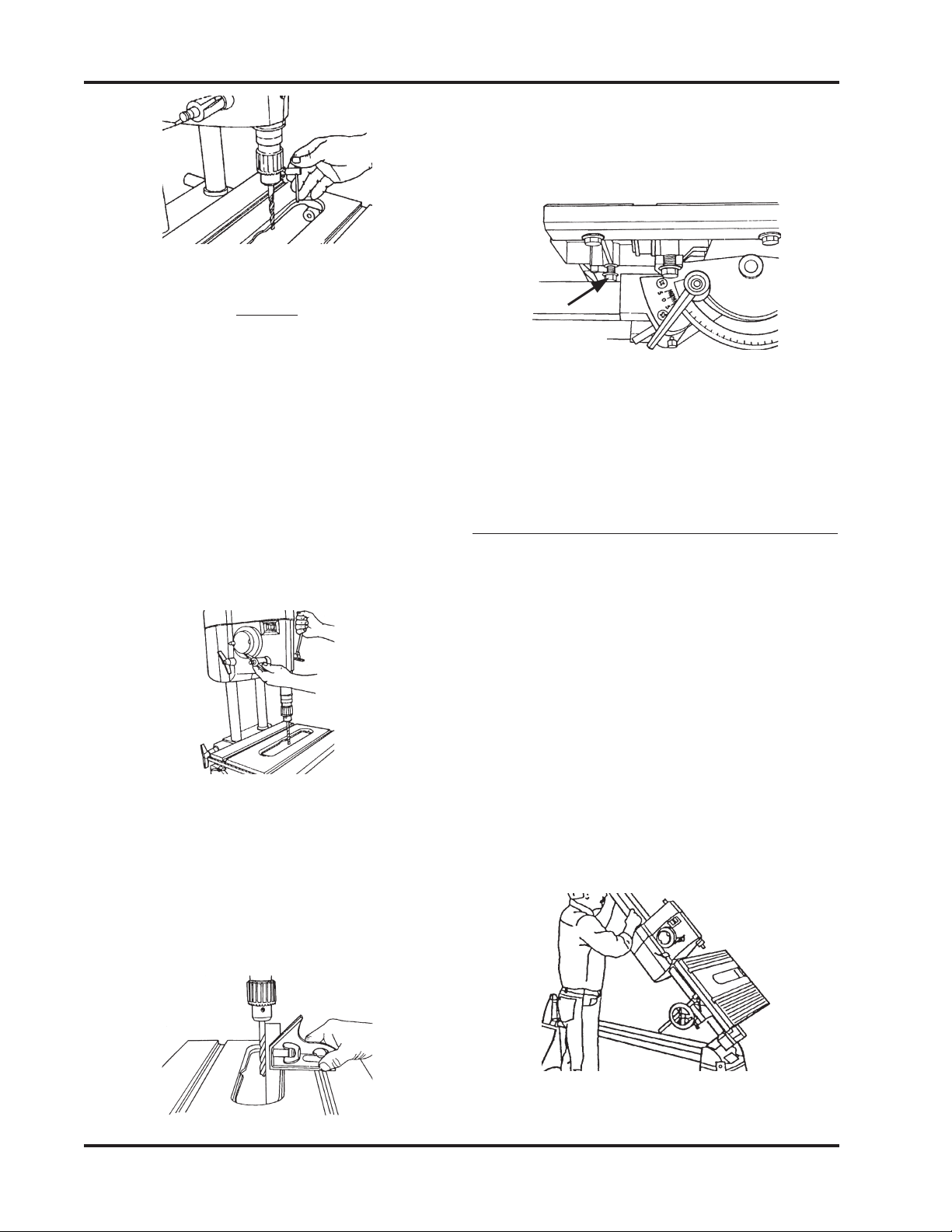
7. Install a 1/2" Straight Drill Bit in the
Drill Chuck and use the Chuck Key to
lock it place. See Figure 8.
SHOPSMITH MARK V 845180
Page 8
10. Both 90° Stops should contact the top of
the Table Support Tubes, as in Figure 11.
If they don't, use a 1/2" Wrench to adjust
the Stops.
Figure 11
11. Recheck the setting by loosening the Tilt
Lock, moving the Table, and then re-
peating Steps 9 and 10. (Rechecking the
setting is very important!)
SET WORKTABLE'S 90° LEFT STOP
(MARK V MODELS 510 & 520)
1. Unlock the Carriage and Headstock.
Move the Headstock to the middle of the
Way Tubes. Then move the Carriage
between the Headstock and Base Mount
(right side).
2. Tighten the Headstock and Carriage
Locks. Place the MARK V in the vertical
position by loosening the Headrest
Handle, firmly grasping the Way Tubes
near the Headrest end, and lifting the
Tubes into the 90° position, as demon-
strated in Figure 12.
Figure 12
Figure 8
NOTE
Check the straightens of the Drill Bit by rolling it
on a flat surface or you can also hand-rotate the
Drill Chuck while holding the Combination Square
against the Drill Bit and the Table. If the Bit is not
straight DO NOT use it for these alignment instruc-
tions.
8. With the Drill Bit above the Table open-
ing, use the Quill Feed to extend the Drill
Bit 1/2" into the Table opening, as in
Figure 9.
Figure 9
9. Set the Combination Square against the
Drill Bit and Table, as shown in Figure
10. The Square should contact the Drill
Bit along its entire length. When the
Tableisexactly perpendicular to theDrill
Bit, lock the Table.
Figure 10
90° STOP
(Front)
Page 9
845180 SHOPSMITH MARK V
WARNING
AlwaysmakesuretheMARKVHead-
stockandCarriagearelockedandall
Castersareraisedoffthefloorbefore
lifting the MARK V into the vertical
Drill Press position.
3. Useyourfingers to tighten the Base Lock.
Figure 13
NOTE
The Base Lock is slightly off center to the counter-
sink found in the Base, as shown in Figure 13. This
offset allows the Base Lock to more firmly hold the
Base Arm in place.
4. Move the Worktable into the 90° posi-
tion by loosening the Table Tilt Lock, as
shown in Figure 14, then putting the
Worktable in the horizontal 90° position,
as shown in Figure 15. Retighten the
Table Tilt Lock only enough to allow
movement with firm pressure.
Figure 14
Figure 15
5. Use a 5/32" Allen Wrench to remove the
Table Insert, as demonstrated in Figure
16.
Figure 16
6. To install the Drill Chuck, mount the
Chuck on the Spindle and align the
Chuck's Set Screw with the Spindle
Knob's Set Screw, as shown in Figure 17.
This allows the Chuck's Set Screw to set
on the flat part of the Spindle. Use a 5/
32" Allen Wrench to securely tighten the
Drill Chuck's Set Screw.
Figure 17
7. Install a 1/2" Straight Drill Bit in the
Drill Chuck and use the Chuck Key to
lock it in place. See Figure 18.

SHOPSMITH MARK V 845180
Page 10
Figure 20
10. When the Table is exactly perpendicular
to the Drill Bit, lock the Table, as seen in
Figure 21.
Figure 21
11. Both 90° Stops (shown in Figures. 22 and
23) should contact the underside of the
Table. If they don't, use a 1/2" Wrench to
adjust the Stops.
Figure 22
90° Stop
(Front)
Figure 18
NOTE
Check the straitness of the Drill Bit by rolling it on
a flat surface or you can also hand-rotate the Drill
Chuck while holding the Combination Square
against the Drill Bit and the Table. If the bit is not
straight DO NOT use it for these alignment instruc-
tions.
8. With the Drill Bit above the Table Open-
ing, use the Quill Feed Handel to extend
the Bit 1/2" into the Table Opening, as
shown in Figure 19.
Figure 19
9. Set the Combination Square against the
Drill Bit and Table, as shown in Figure
20. The Square should contact the Drill
Bit along its entire length.
Page 11
845180 SHOPSMITH MARK V
Figure 23
12. Recheck the setting by loosening the Tilt
Lock, moving the Table, and then re-
peating Steps 9 through 11. (Rechecking
the settings is very important!)
SET THE WORKTABLE'S 0° STOP
1. Remove the Drill Bit and Drill Chuck
from the Spindle.
2. Loosen the Base Lock. Firmly grasp the
Way Tubes and lower the Headstock
into the horizontal position, then engage
the Headrest.
3. Loosen the Table Tilt Lock and place the
Table in the horizontal 0° position. Re-
tighten the Table Tilt Lock only enough
to allow movement with firm pressure.
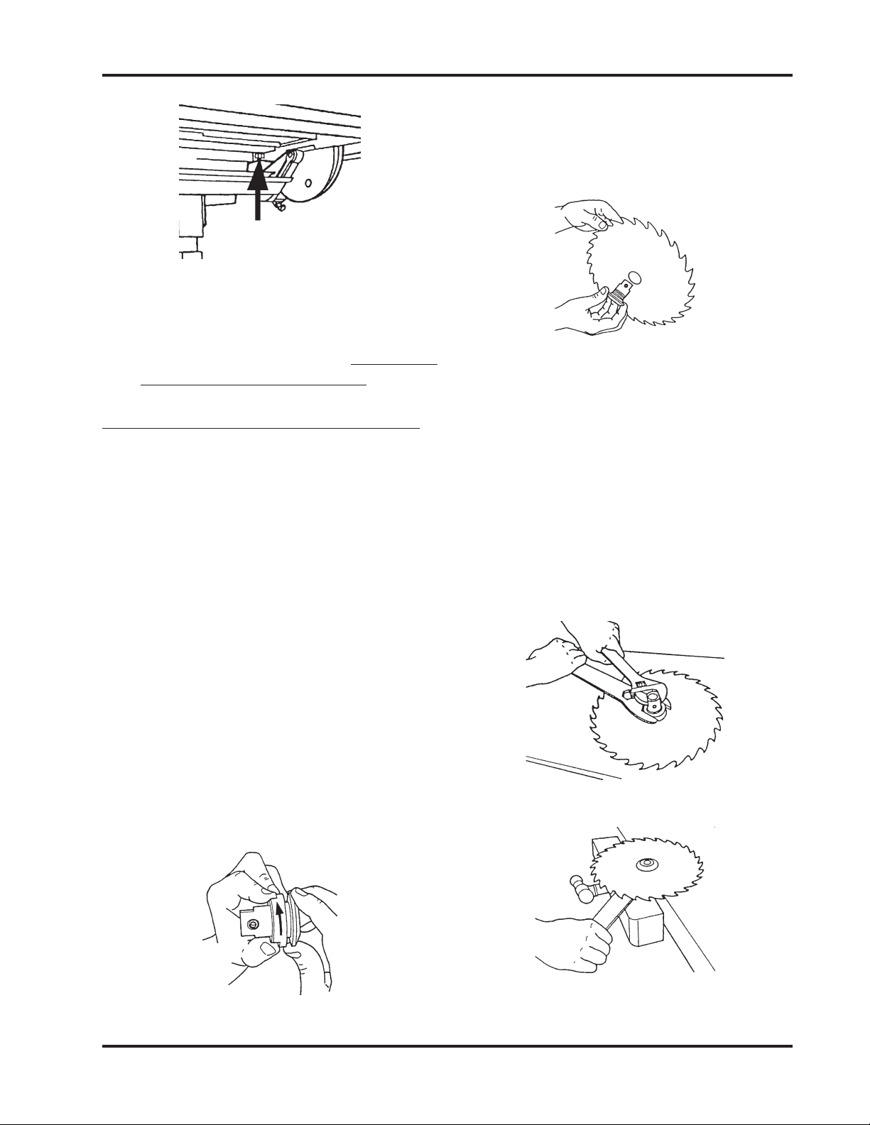
4. Mount the Saw Blade on the Arbor:
b. HoldtheBladewiththeteethpoint-
ing toward you, as shown in Figure
25, then insert the Arbor through
the hole. Replace the Nut and fin-
ger tighten it.
90° Stop
(Rear)
a. Remove the Arbor Nut by turning
it clockwise, as seen in Figure 24.
Hold the Arbor with the threaded
part pointing to the left.
c. Place the Blade and Arbor on your
Workbench with the Nut pointing
up.
d. Hold the Arbor with an Adjustable
Wrench and tighten the Arbor Nut
with the Arbor Wrench, as demon-
strated in Figure 26. Another way
to tighten the Arbor Nut is to clamp
the Arbor in a Bench Vise, as illus-
trated in Figure 27, and tighten the
Nut with the Arbor Wrench.
Figure 24
Figure 25
Figure 26
Figure 27
SHOPSMITH MARK V 845180
Page 12
10. Place the Combination Square against
both the Saw Blade and Worktable, as
seen in Figure 32. Make sure the square's
blade does not touch a saw tooth and
does rest in a gullet between teeth.
Figure 32
11. If the Worktable is not exactly perpen-
dicular to the Saw Blade, adjust the
Worktable so it is perpendicular to the
Saw Blade, then tighten the Tilt Lock.
(MARK V MODEL 500)
12. Use a Small Screwdriver to back out the
0° stop 2-3 turns. Depress the Plunger
WARNING
The only time the Saw Blade is used
without the Upper or Lower Saw
GuardsisduringalignmentandONLY
after the MARK V is turned off and
unplugged.
5. Mount the Saw Blade on the Spindle and
align the Arbor Set Screw with the
Spindle Knob's Set Screw, then use a 5/
32" Allen Wrench to tighten the Arbor
Set Screw.
6. Reinstall the Table Insert in the Work-
table.
7. Raise the Worktable so that it clears the
top of the Saw Blade.
8. Loosen the Carriage Lock and slide the
Carriage so the Saw Blade is directly
beneath the slot in the Table Insert. See
Figure 28 or 29. Tighten the Carriage
Lock.
MARK V Model 500
Figure 28
MARK V Models 510 & 520
Figure 29
9. Lower the Worktable (nearly all the way
down) so the Saw Blade comes through
the slot. Lock the Table Height, as seen in
Figure 30 or 31.
Figure 31
MARK V
Models 510 & 520
Figure 30
MARK V
Model 500
Page 13
845180 SHOPSMITH MARK V
ADJUSTTHEWORKTABLE'S 45°STOP
(MARK V Model 500)
1. Loosen the Table Height Lock and raise
the Table until it clears the Saw Blade.
Tighten the Height Lock.
2. Loosen the Tilt Lock and tilt the Work-
table to the right.
3. Tighten the Tilt Lock only enough to
allow movement with firm pressure.
4. Loosen the Quill Feed (shown in Figure
37) and extend the Quill so the Saw
under the Table Tilt Indicator up toward
the Front Trunnion, and hole it there
with your finger. Slowly turn the 0° stop
in until you feel it just touch the Plunger.
See Figure 33.
Figure 33
13. Recheck the setting by repeating Steps
10 through 12. (It is very important to
recheck this setting!)
(MARK V MODELS 510 & 520)
12. To adjust the 0° Stop, simultaneously
depress the Table Stop Pin and use a 1/
2" Wrench to adjust the Stop Bolt. The
Stop Bolt should just contact the side of
the Stop Pin. Once the Stop Bolt is ad-
justed, the Stop Pin will "snap" back
when the Tilt Lock is tightened. See Fig-
ure 34.
Figure 34
13. Loosen the Tilt Lock, tilt the Worktable,
then depress the 0° Stop Pin until the
Stop Bolt contacts it. Tighten the Tilt
Lock, and recheck the setting by repeat-
ing Steps 10 through 12. (It is very impor-
tant to recheck this setting!)
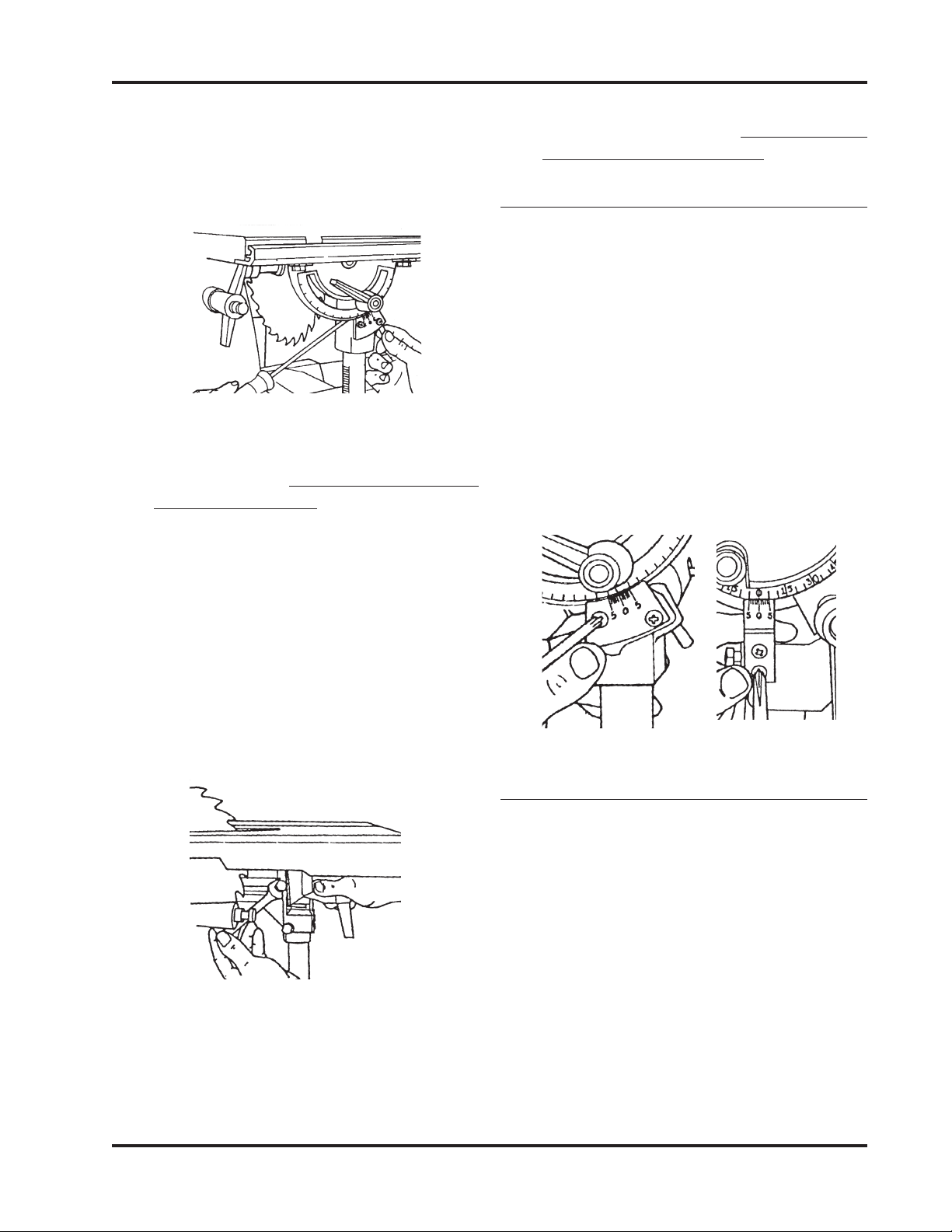
ADJUSTTHETABLE TILT INDICATOR
1. Tighten the Table Tilt Lock and check
that the 0° mark on the Indicator aligns
with the 0° mark on the Trunnion.
2. Toadjust the scale,usea MediumPhillips
Screwdriver to loosen the two Screws
which hold the Indicator to the Tie Bar.
See Figure 35 or 36. Then while holding
the Indicator in position so the 0's are
aligned, retighten the Screws.
MARK V
Model 500
Figure 35
MARK V
Models 510 & 520
Figure 36

SHOPSMITH MARK V 845180
Page 14
7. Loosen the Tilt Lock and tilt the Table
past the 45° setting. Then depress the
Plunger and tilt the Table back toward
that angle until the Stop hits the Plunger.
Tighten the Tilt Lock, then check the
angle. If the angle is not 45°, the Stop
needs adjusting.
8. To adjust the 45° Right Stop, see Figure
40. Set the Table to 45° Right. Then use
the Combination Square to set the tilt of
the Table to precisely 45° Right. Use a
Small Screwdriver to back out the 0° stop
2-3 turns. Depress the Plunger under the
Table Tilt Indicator up toward the Front
Trunnion, and hold it there with your
finger. Slowly turn the 45° Stop in until
you fell it touch the Plunger.
Figure 40
9. Loosen the Tilt Lock and move the Table.
To recheck the 45° Stop, repeat Steps 4
through 9. (It is very important to re-
check the setting!)
ADJUSTTHEWORKTABLE'S 45°STOP
(MARK V MODELS 510 & 520)
1. Loosen the Table Height Lock and raise
the Table until it clears the Saw Blade.
Tighten the Height Lock.
2. Loosen the Tilt Lock and tilt the Work-
table to the right until it makes contact
with the two 45° Stop Bolts.
3. Tighten the Tilt Lock only enough to
allow movement with firm pressure.
Blade is centered beneath the slot in the
Table Insert. When it is centered, lock the
Quill Feed.
Figure 37
5. Lower the Worktable so the Saw Blade
extends through the Table Insert slot.
See Figure 38. Lock the Table Height.
Figure 38
6. Remove the Blade from the Combina-
tion Square and place the Square against
the Saw Blade and the Worktable, as
shown in Figure 39. Make sure the Com-
bination Square doesn't rest on the Table
Insert.
Figure 39

Page 15
845180 SHOPSMITH MARK V
4. Loosen the Quill Feed (shown in Figure
41) and extend the Quill so the Saw
Blade is centered beneath the slot in the
Table Insert. When it is centered, lock the
Quill Feed.
Figure 41
5. Lower the Worktable so the Saw Blade
extends through the slot. See Figure 42
Lock the Table Height.
Figure 42
6. Remove the bar from the Combination
Square and place the square against the
Saw Blade and the Worktable, as shown
in Figure 43. Make sure the Combination
Square doesn't rest on the Table Insert.
Figure 43
7. If the Worktable is not exactly 45° to the
Saw Blade, adjust the Worktable so it is.
8. Tighten the Tilt Lock, then use a 1/2"
Wrench to adjust the 45° Stop on the
front side of the Worktable (shown in
Figure 44).
Figure 44
9. Also, the back side of the Worktable
(shown in Figure 45). The stops should
just contact the underside of the Table.
Figure 45
10. Loosen the Tilt Lock and move the Table.
To recheck the 45° stops, repeat Steps 4
through 8. (It is very important to re-
check the setting!)
ALIGN THE MITER GAUGE SLOTS
1. Return the Worktable to the horizontal
0° stop and tighten the Tilt Lock. The
Carriage Lock and Headstock Lock
should also be tightened.
2. Place the Miter Gauge in the Right Miter
GaugeSlot, anduse a5/32"Allen Wrench
to remove the Quick Clamp from the
Safety Grip, as shown in Figure 46.

SHOPSMITH MARK V 845180
Page 16
Figure 48
Figure 49
5. If the Miter Slots need to be aligned, do
the following:
(MARK V MODEL 500)
Figure 50
a. Use a 9/16" Wrench to loosen the
Bolts which hold the Worktable to
the Trunnions, (Front Trunnion
Bolts shown in Figure 50) and the
Table Base. Loosen these four Bolts
only enough to allow movement
with firm pressure.
Figure 46
3. Insert the Long 5/32" Allen Wrench
through the Miter Gauge. Borrow a Set
Screw from the Lathe Tool Rest and use
the Short 5/32" Allen Wrench to install it
in either top Miter Gauge hole, as seen in
Figure 47. Place the tip of the Long
Wrench against the front side of the Saw
Blade and tighten the Set Screw.
Figure 47
4. MovetheMiter Gauge from front to back
along the Saw Blade, as shown in Figs. 48
and 49. If it hangs up on the Blade or a
gapdevelops, the MiterGaugeSlots need
to be aligned. Make sure the Allen
Wrench does not contact a Saw Blade
tooth, because the tooth "set" will cause
misalignment.
Trunnion Bolts
(Front)

Page 17
845180 SHOPSMITH MARK V
Figure 51
b. Adjust the Worktable, then again
move the Miter Gauge and Wrench
along the face of the Saw Blade
until the Wrench tip consistently
contacts the entire Saw Blade sur-
face.
c. When the Miter Gauge Slot is
aligned, tighten the two Trunnion
Bolts which are closer to the Head-
stock. Then tighten the other two
Trunnion Bolts.
d. LoosentheTableTiltLockandmove
the Table, then return it to the hori-
zontal 0° position. Recheck the Slot
alignment. If it is off, repeat steps 5a
through 5c. (It is very important to
recheck this setting!)
(MARK V MODELS 510 & 520)
a. Tilt the Table to 45° and tighten the
Tilt Lock.
b. Use a 5/16" Allen Wrench to loosen
all four Bolts which hold the Work-
table to the Trunnions, as pointed
out in Figure 51. Loosen the Bolts
only enough to allow movement
with firm pressure.
c. Position the Worktable back to the
horizontal 0° and tighten the Tilt
Lock.
d. Adjust the Worktable, then again
move the Miter Gauge and Wrench
along the face of the Saw Blade
until the Wrench tip consistently
contacts the entire Saw Blade sur-
face.
e. When the Miter Gauge Slot is
aligned, use the 5/16" Allen
Wrench to retighten the two Trun-
nion Bolts which are closer to the
Headstock. Then loosen the Table
Tilt Lock, tilt the Worktable to 45°,
and tighten the Table Tilt Lock. Use
the 5/16" Allen Wrench to tighten
the other two Trunnion Bolts.
NOTE
If you find it difficult to loosen the Bolts, consider
using a T-Handle Allen Wrench, or use a Box End
Wrench for extra torque. Another alternative is to
use the hanging hole in an Adjustable Wrench, as
demonstrated in Figure 52 and 53.
Figure 52
Figure 53
Trunnion Bolts

SHOPSMITH MARK V 845180
Page 18
slide it back and forth in the Slot to check
if the Miter Gauge scrapes against the
Table.Ifthe Miter Gauge rocks or scrapes
the Table, adjust the Glides.
Figure 56
3. If the Glides need to be adjusted, do the
following:
Miter Gauge shown
before adjusting the glides.
a. Remove the Miter Gauge from the
Slot and turn it over.
b. Use a Medium Screwdriver to ad-
just the Glides in or out, as illus-
tratedin Figure 71,so that theGlides
hold the Miter Gauge 1/64" to 1/
32" off the Worktable and the Miter
Gauge does not rock in the Slots.
Figure 57
4. Return the Miter Gauge to the Slot and
recheck and readjust it, if needed.
ADJUST THE MITER GAUGE FACE
1. Remove the Safety Grip from the Miter
Gauge.
2. Put the Miter Gauge in the Right Slot and
place the Combination Square against
the Saw Blade and Miter Gauge Face, as
seen in Figure 58.
NOTE
Tighten the Bolts only after the Table Tilt Lock is
secured. Otherwise the Worktable will bow or bind
the next time the Table Tilt Lock is tightened.
INSTALL THE TABLE INSERT
1. Place the Table Insert in the Worktable
recess. Use a 5/32" Allen Wrench to start
both screws. See Figure 54.
Figure 54
2. First tighten the rear screw. Then the
front of the insert will be sprung slightly
above the Table. Level the insert by plac-
ing your hand on the front of the insert,
and slowly turning the front screw until
it draws the front of the insert flush with
the Worktable surface. Shown in Figure
55.
Figure 55
ADJUST THE MITER GAUGE GLIDES
1. Place the Miter Gauge in the Worktable's
Miter Gauge Slot.
2. Check to see if the Miter Gauge wobbles
side-to-side, typified by Figure 56. Also,

Page 19
845180 SHOPSMITH MARK V
ADJUST THE 90° POSITIVE STOP
1. Use a Small Screwdriver to back out the
90° Stop Screw 2 to 3 turns, as shown in
Figure 61.
Figure 61
2. Depress the Plunger, then turn the Stop
Screw until you feel it touch the Plunger.
ADJUST BOTH 45° STOPS
1. Loosen the Lock Knob and pull out the
Plunger. Then, at the same time, rotate
the Miter Gauge and push in the Plunger
until it hits the 45° Stop (there is one on
each side of the 90° Stop).
2. Use a Combination Square to set the
MiterGaugeFaceat45° to the Saw Blade.
If the 45° Stop needs adjustment, use a
Medium Screwdriver to back out the 45°
Screw 2 to 3 turns.
3. Depress the Plunger, then turn the Stop
Screw until you feel it touch the Plunger.
4. To adjust the other 45° Stop, repeat Steps
1 to 3.
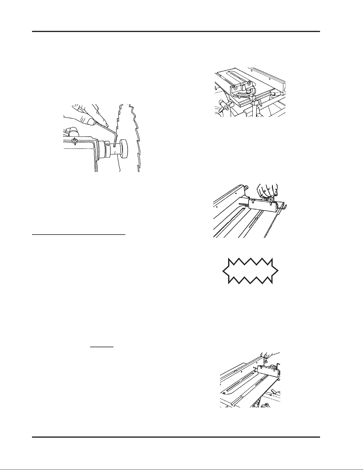
REMOVE THE SAW BLADE
1. Loosen the Table Height Lock and raise
the Table so that it clears the Saw Blade,
a. Use a Long Allen Wrench to loosen
the Lock Knob and adjust the Miter
Gauge so it is perpendicular to the
Saw Blade, then tighten the Lock
Knob. See Figure 59.
Figure 59
b. Use a Medium Screwdriver, loosen
the Screw which holds the Indica-
tor Plate, and set its 0° to the Miter
Gauge's 90°. Tighten the Screw. See
Figure 60.
Figure 58
3. If the Miter Gauge Face is not perpen-
dicular to the Saw Blade, do the follow-
ing:
Figure 60
90° Stop
45° Stop
45° Stop
SHOPSMITH MARK V 845180
Page 20
then tighten the lock. Unlock the Car-
riage Lock and move the Worktable to
the right.
2. Use the 5/32" Allen Wrench to loosen
the Arbor Set Screw. Remove the Saw
Blade. See Figure 62.
Figure 62
3. Unlock the Table Height Lock and lower
the Table to a comfortable working
height. Tighten the Lock.
ALIGN THE RIP FENCE
(MARK V MODEL 500 STYLE 1)
1. Place the Rip Fence on the Worktable by
first putting the Fence Base on the Front
Rail, then lowering the rest of the Rip
Fence.
2. Use a 5/32" Allen Wrench to back out the
two Adjusting Set Screws from the Fence
Base so they don't contact the infeed
edge of the Table Rail.
NOTE
The Outfeedlock should press against the bottom
edge of the Table, not hook under it. As you tighten
the Locking Handle, a clamp just behind the Fence
Base pulls the Rip Fence so the Fence Base rests
flush against the Table mounting bar, and is now
automatically aligned to the Blade. The Outfeed
Lock now secures the Fence at the same time.
3. Place the Miter Gauge in the Left Slot of
the Worktable on the infeed side, as
shown in Figure 63.
Figure 63
4. Insert the Long 5/32" Allen Wrench
through the Miter Gauge and secure it
using a Short 5/32" Allen Wrench and a
Set Screw borrowed from the Lathe Tool
Rest, as seen in Figure 64.
Figure 64
CAUTION
Be sure the end of the Allen Wrench is smooth.
Watchthatyoudon'tscratchtheRipFencesurface.
5. Move the Rip Fence toward the Allen
Wrench until it just touches it. When is
doestouchthe Fence, lock the Base Knob,
as in Figure 65.
Figure 65
Other manuals for MARK V
1
Table of contents
Other Shopsmith Wood Router manuals


Popular Wood Router manuals by other brands

BLUM
BLUM M35.ZS00 Safety, operating and maintenance instructions

ARF CNC
ARF CNC 6040 user manual

Mafell
Mafell LO 55 Translation of the original operating instructions

Craftsman
Craftsman 720.25251 owner's manual

MasterForce
MasterForce 241-0836 operating manual

Professional Woodworker
Professional Woodworker 46662 manual


