Shopsmith MARK V PRO User manual
MARK
V
PRO
FENCE
ROUTER
TABLE
521962
-
-
-
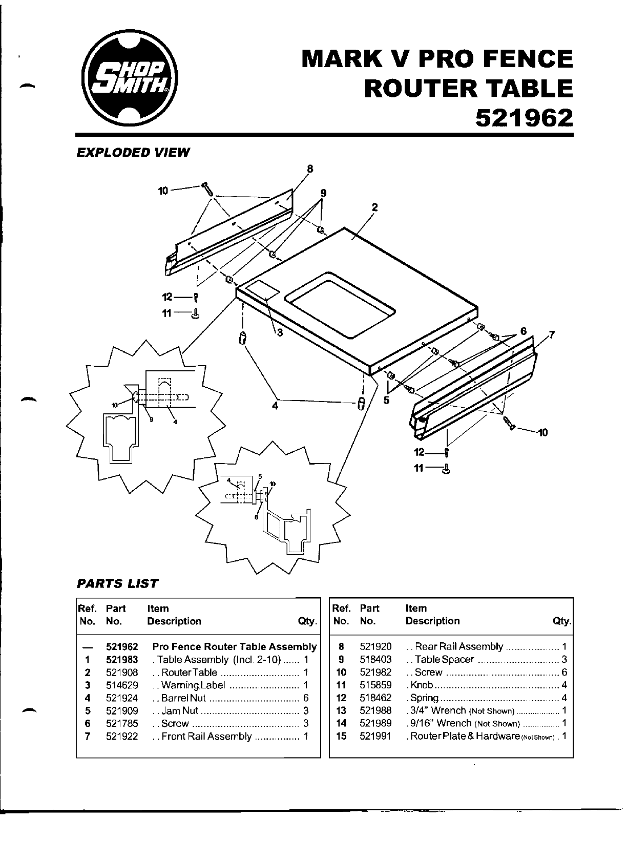
EXPLODED
VIEW
8
PARTS
LIST
Ref.
Part
Item
No. No.
Description
Qty.
-521962
Pro
Fence
Router
Table
Assembly
1 521983 ·TableAssembly (Inc!. 2-10) ...... 1
2 521908 · .RouterTable ............................ 1
3 514629 ·.
WamingLabel
......................... 1
4 521924 ·.BarreiNut ................................ 6
5 521909 · .Jam Nut ... ........................... .
..
3
6 521785 · .Screw ...................................... 3
7 521922 · .Front Rail Assembly ................ 1
Ref.
Part
No. No.
8 521920
9 518403
10
521982
11
515859
12
518462
13
521988
14 521989
15
521991
Item
Description
Qty.
..
Rear Rail Assembly
.....
......
....
1
TableSpacer
........ ..........
....
.... 3
.. Screw .................... ................... 6
.Knob.
........
.
.............
...
............. 4
.Spring ...................... ....... ........... 4
.3/4" Wrench (Not Shown)
...
...............
1
.9/16" Wrench (Not Shown) ................ 1
.
RouterPlate
& Hardware,N'lsh'W"' . 1
7
MARKVPROFENCEROUTERTABLE
521962
INTRODUCTION
The
Router
Table
can
be
used
with
the
shopsmith
MARKVPro Unit.
This instruction
manual
coverssafety, assem-
bly, alignment, operations
and
care of the
RouterTable.Read
through
the
entire
manual
before assembling
and
operating
the Router
Table.
SAFETY
The MARK V Pro Fence Router Table has
many
built-in safety-features,
but
the effec-
tivenessof
them
depends
on
you.
Power
Tool
safety requires
good
common
sense. Misuse
of this tool
can
cause
serious
injury.
Throughout
thismanual,
welist
WARNlNGs,
CAUTlONs,
and
NOTES. Weadvisethat
when
you
come to
one
of these
headings
that
you
read
them
until fully understood.
Their meanings are:
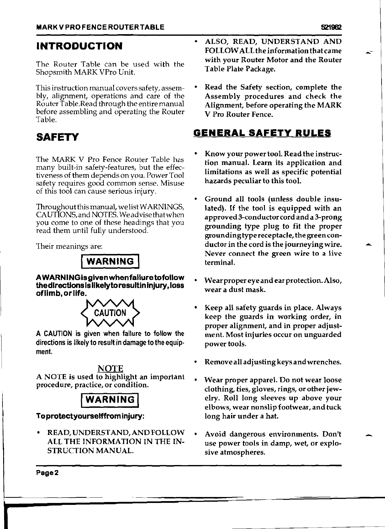
I-W-A--RN-I~NG--I
A
WARNINGisgivenwhenfailuretofollow
thedirections
Is
IikelytoresultlnInjury,loss
oflimb,
or
life.
A
CAUTION
is
given
when
failure
to
follow
the
directions
is
likely
to
result
in
damage
to
the
equip·
ment.
NOTE
A
NOTE
is
used
to
highlight
an
important
procedure,
practice,
or
condition.
I
WARNING
I
Toprotectyourselffrominjury:
• READ,
UNDERST
AND,
AND
FOLLOW
ALL
THE
INFORMATION
IN
THE IN-
STRUCTION
MANUAL.
• ALSO, READ,
UNDERSTAND
AND
FOLLOW
ALL
the
information
that
came
--
with
your
Router
Motor
and
the
Router
Table
Plate
Package.
•
Read
the
Safety
section,
complete
the
Assembly
procedures
and
check
the
Alignment,
before
operating
the
MARK
V Pro
Router
Fence.
GENERAL
SAFETY..
RULES
•
Know
your
power
tool.
Read
the
instruc-
tion
manual.
Learn its
application
and
limitations
as
well
as specific
potential
hazards
peculiar
to
this
tool.
•
Ground
all tools
(unless
double
insu-
lated).
If
the
tool
is
equipped
with
an
approved
3-conductor
cord
and
a
3-prong
grounding
type
plug
to
fit
the
proper
grounding
type
receptacle,
the
green
con-
ductor
in
the
cord
is
the
journeying
wire.
...
Never
connect
the
green
wire
to
a
live
terminal.
•
Wear
proper
eye
and
ear
protection.
Also,
wear
a
dust
mask.
•
Keep
all
safety
guards
in
place.
Always
keep
the
guards
in
working
order,
in
proper
alignment,
and
in
proper
adjust-
ment.
Most
injuries
occur
on
unguarded
power
tools.
•
Remove
all
adjusting
keys
and
wrenches.
•
Wear
proper
apparel.
Do
not
wear
loose
clothing, ties, gloves, rings,
or
other
jew-
elry. Roll
long
sleeves
up
above
your
elbows,
wear
nonslip
footwear,
and
tuck
long
hair
under
a
hat.
•
Avoid
dangerous
environments.
Don't
use
power
tools
in
damp,
wet,
or
explo-
sive
atmospheres.
Page2
5'21962
MARKVPROFENCEROUTERTABLE
•
Keep
works
area
well
lit, clean,
and
free
from
clutter.
-•
Do
not
force
the
tool.
It
will
do
the
job
better
and
safer
atthe
rate
for
which
it
was
designed.
•
Use
the
right
tool.
Do
not
force a
tool
or
accessory
to
do
a
job
for
which
itwas
not
designed.
• For
directional
feed,
ALWAYS
feed
the
workpiece
into
the
cutter
against
the
rota-
tion
of
the
cutter.
NEVER
feed
the
workpiece
into
the
cutter
with
the
rota-
tion
of
the
cutter.
-
•
Check
for
damaged
parts.
A
damaged
guard
or
part
must
be
properly
repaired
or
replaced
before
further
use
of
the
tool.
If
a
strange
noise
or
vibration
develops,
immediately
turn
off
the
power,
unplug
the
machine
and
correct
the
problem.
Never
operate
a
power
tool
that
is
not
functioning
properly.
•
Secure
workpieces.
Use
clamps,
fixtures
and
other
devices
to
hold
workpieces
when
practical.
It's
safer
than
using
your
hands
and
frees
your
hands
to
operate
the
tool.
•
Do
not
overreach.
Keep
proper
footing
and
balance
at all
times.
•
Turn
off
the
tooland
waituntilitcomes
to
a
complete
stop
before
removing
workpieces
and
scraps.
•
Do
not
try
to
stop
the
tool
by
grabbing
the
workpiece
or
any
part
of
the
tools.
Turn
off
the
tool
and
let
it
come
to
a
complete
stop
by
itself.
•
Do
not
leave
the
tool
runningunattended.
-
Turn
off
the
power.
Don't
leave
the
tool
until
it
comes
to a
complete
stop.
•
Avoid
unintentional
starting.
Make
sure
the
switch
is
in
the
"off"
position
before
plugging
in
or
unplugging
the
tool.
•
Disconnect
tools.
Turn
off
and
unplug
tools
before
changing
accessories,
setups,
making
adjustments,
performing
main-
tenance,
or
repairs.
•
Do
not
stand
or
lean
on
the
tool. You
could
fall
into
the
tool
oritcould
tip
over
injuring
you
and/or
the
tool.
•
Maintain
tools.Keep
parts
and
toolssharp,
clean,
and
maintained
according
to
the
instruction
manual.
•
Make
your
workshop
child
proof.
Use
padlocks,
master
switches
and
remove
starter
keys.
•
Keep
children
away.
All
visitors
must
stay
a safe
distance
from
power
tools,
and
wear
ear
and
eye
protection.
•
Do
not
permit
anyone
who
is
inexperi-
enced
to
use
your
power
tools
without
proper
supervision.
MARK
V
PRO
FENCE
ROUTER TABLE SAFETY
RULES
• Be
sure
to
read
and
understand
this
en-
tire
instruction
manual
before
using
the
MARK
V Pro Fence
Router
Table.
Also,
do
not
use
the
MARK
V ProFence
Router
Table
unless
you
are
sure
it
is
assembled
properly,
all
safety
devices
are
installed,
and
you
understand
the
operations
you
are
attempting.
•
Keep
the
Guard
in
place
and
in
working
order.
Always
setthe
Guard
no
more
than
1/4"
above
the
workpiece.
I
Page3
I
I
~
~iiiiiiiiO==--====~-~~--
I

MARKVPROFENCEROUTERTABLE
521962
•
Keep
your
hands,
fingers,
and
other
parts
of
your
body
at
least
3"
away
from
the
rotating
bit.
•
Use
a
Push
Stick,
Push
Block,
Feather
Board(s),fixtures,
or
other
safety
devices
to
maneuver
a
workpiece
into
a
rotating
bit.
If
a
kickback
occurs,
these
devices
help
to
protect
your
hands
and
fingers.
•
Use
only
Shopsmith
Parts
and
Accesso-
ries
on
your
MARK
V
Pro
Fence
Router
Table.
NEVER
use
non-Shopsmith
Re-
placement
Parts
or
Accessories.
They
are
not
designed
like
Shopsmith
Parts. Us-
ing
non-Shopsmith
Parts
may
create
a
hazardous
condition
and
will
void
your
warranty.
Follow
your
Router
Motor
manufacturer's
recommendations
as
to
Replacement
Router
Motor
Parts.
•
Do
not
Rout
secondhand
lumber.
If
you
hit
a
nail,
screw,
or
other
foreign
object,
you
could
be
hit
by
pieces
of
metal
or
there
could
be
kickback.
•
Do
not
"freehand"
Rout
stock
less
than
12" x12"
or
equivalent.
•
Support
long
boards
and
sheet
materials
with
a
Roller
Stand(s)
placed
l'
to 4'
from
the
Worktable.
•
Always
use
a Fixture,Fence,
Miter
Gauge
with
Safety
Grip,
and/or
Starter
and
Guide
Pins
to
help
control
the
workpiece.
•
Always
feed
the
workpiece
against
the
rotation
of
the
bit,
not
with
it.
Otherwise,
the
bitwiJIgrab
and
throw
the
workpiece.
•
Keep
a
firm
grip
on
the
workpiece
at
all
times
and
never
hold
the
workpiece
with
your
hands
in
line
with
the
Router
Bit.
•
Always
use
a
Feather
Board
Assembly
or
other
devices
to
hold
or
guide
narrow
workpieces.
Also,
use
a
long
piece
of
scrap
stock
to
feed
narrow
workpiece
underneath
the
Guard
to
complete
a cut.
•
Cut
with
the
grain
of
the
wood
instead
of
against
it. You
will
get
a
smoother
cut
and
the
operation
will
be
safer.
•
Avoid
standing
in-line
with
the
workpiece
being
fed.
In
the
event
of
a
kickback
you
could
be
hit.
• Feed
the
workpiece
slowly.
Use
extracare
in
routing
workpieces
that
contain
fig-
ured
grain
of
knots,
as
these
may
cause
kickbacks.
•
When
you
are
routing
stock
up
to
10"
wide
across
the
grain,
use
your
Miter
Gauge
with
Safety
Grip
to
control
the
workpiece.
The
workpiece
must
extend
5-1/2"
away
from
the
router
bit.
•
When
stop
routing,
always
you
a
Stop
Block(s) to
control
the
length
of
cut. Fail-
ure
to
use
Stop
Blocks
could
cause
the
bit
to
grab
and
throw
the
workpiece.
•
When
routing
oversized
stock,
always
use
a
least
one
Push
Block
to
help
control
the
workpiece
firmly
against
the
fence.
•
Do
not
work
with
stock
thatis
too
small
or
too
large
to
handle
safely;
that
is
warped,
bowed,
or
cupped;
or
that
has
loose
knots
or
other
defects.
•
Plan
the
operation
before
you
begin.
If
you
are
in
doubt
about
how
to
complete
an
operation
safely,
do
not
attempt
it,
contact
a
Shopsmith
Service
Representa-
tive
for advice.
• Free
freehand
routing
use
a
Guide
Pin,
do
not
rout
a
workpiece
which
has
less
-
than
a
4"
radius.
Page4
r

521962
MARKVPROFENCEROUTERTABLE
•
The
minimum
length
of
stock
should
be
no
less
than
8".
You
should
also
use
a
-
Push
Stick
and/or
Push
Block
on
any
stock
between
8"
to
18"
long.
EYE
PROTECTION
Always
wear
eye
protection
when
you
use
power
tools.
Use
Goggles,
Safety
Glasses
or
a Face
Shield,
to
protect
your
eyes.
•
Goggles
completely
surround
and
pro-
tectyour
eyes.
Many
Goggles
will
also
fit
over
Regular
Glasses.
Be
sure
your
Goggles
fit
closely,
but
comfortable.
•
Safety
Glasses
don't
fog
as
easily
as
Goggles
and
can
be
worn
at
all
times.
Regular
Glasses
normally
have
only
im-
pact
resistant
lenses.
They
are
not
Safety
Glasses.
• A Face
Shield
protects
your
entire
face,
-
not
just
your
eyes.
HEARING
PROTECTION
Prolonged
exposure
to
high
intensity
noise
from
high-speed
power
tools
can
damage
your
hearing.
•
Hearing
Protectors
screen
out
noise
lev-
els
that
can
damage
your
ears,
and
are
recommended
for
ALL
uses
with
Routers
mounted
in
Router
Tables.
GUARDING
FOR
RQUTING
Most
shop
accidents
happen
to
woodwork-
ers
who
fail
to
follow
instructions,
or
fail
to
use
Guards
and
Safety
Devices.
Although
proper
use
of
Guards
and
Safety
Devices
often
requires
additional
setup,
the
protec-
tion
for
you
and
your
family
is
well
worth
the
-effort.
DRESS
Loose
hair
and
clothing,
which
could
be
entangled
in
rotating
bits,
are
very
hazard-
ous.
•
Tuck
long
hair
under
a
hat
or
tie
it
up
above
the
shoulders.
Do
not
wear
ties,
gloves,
loose
clothing,
rings
or
other
jew-
elry.
Roll
sleeves
up
above
your
elbows.
ELECTRICAL
REQUIREMENTS
Follow
the
electrical
requirements
that
ap-
pear
in
the
instruction
manual
that
cam
with
your
Router
Motor.
Do
not
overload
your
electrical
circuits
UNDER-TABLE
MOUNTED
ROUTER
The
Router
is
not
included
with
the
MARK
V
Pro
Fence
Router
Table.
You
will
have
to
purchase
a
Router
or
use
one
that
you
al-
ready
own.
Any
UL
approved
router
can
be
used.
The
specifications
for
the
router
that
you
can
use
are:
•
Use
only
UL
approved
Routers
•
The
Router
must
not
exceed
3
hp.
•
The
Router
switch
is
best
located
so
that
it
can
face
toward
the
front
of
the
Mark
V
Router
Table.
It
can
then
be
easily
and
safely
reached
during
operations.
•
The
Router
switch
must
be
able
to
stay
in
the"
on"
position
without
being
held
by
hand.
It
also
must
easily
switch
off
as
needed.
Page5
•
MARKVPROFENCEROUTERTABLE
521962
•
The
Shop
smith
Accessory Switch is rec-
ommended
if
the
router
motorswitch
does
not
meet
the above criteria.
SAWDUST
AND
CHIPS
Sawdust
and
chips
can
be a fire
hazard
and
breathing
sawdust
can
be
a health hazard.
The
sawdust
from
some
woods
is toxic. To
help
protect
yourself
from
sawdust:
• Attach
the
MARK
V Pro
Router
Table
to
a
dust
collection
system.
•
Or
wear
a close-fitting
dust
mask.
Clean
or
replace
the
filters
in
the
mask
regu-
larly. Also,
open
a
window
or
use
a
fan
to
ventilate
your
shop.
MOUNTING
ROUTER
BITS
•
Turn
off
and
unplug
the
Router
before
mounting
router
bits.
•
Follow
the
recommendations
of
the
Router
manufacturer
as to
the
sizes
and
types
of
router
bits
to use.
•
Make
sure
the
router
bit
is
secured
prop-
erly
in
the
collet. Loose
bits
could
work
free
and
cause
serious
injury.
Insetthe
bit
all
the
way
into
the collet
and
retract
it
a
bout
1/8"
to
avoid
transferring
vibra-
tions
to
the
motor
armature
and
bending
the
shank
of
the
bit.
• Be
sure
the
bit
is
positioned
with
the
cutting
edge
facing
to
the
right.
•
Listen
for
chatter
or
signs
of
looseness
at
start-up.
If
you
hear,
see
or
suspect
prob-
lems,
stop
the
tool
immediately,
unplug
it,
and
check
the
tool
thoroughly.
Correct
any
problem
before
proceeding.
If
you
are
unable
to locate
the
problem,
you
can
contact
your
Shopsmith
Service Repre-
sentative
or
store
personnel
for advice.
Never
operate
the
Mark
V
Router
Table
if
it
is
not
functioning
properly.
•
Keep
bits
clean,
maintained
and
sharp.
•
Don'ttryto
make
your
own
collet
adapter
to
hold
different
sized
bits. Balance
is
important
at
high
speeds,
so
always
buy
appropriately
sized
collets.
TYPES
OF
ROU"rER
BITS
Router bits come in a
wide
variety
of
shapes
and
sizes designed to
be
used
at
very
high
speeds. The
part
of
the
bit
mounted
in
the
router
chuck
is called
the
shank
and
the
rounded
extension
beyond
the
cutter
on
some
bits is called the pilot. The cutting
edge
of
the
bitis called a flu
teo
Router bits have one,
two
or
threeflutes
and
the
more
flutes
there
are
on
the
bit, the
more
cuts
that
can
be
made
per
minute. A
higher
number
of
flutes reduces
theloadon the
motor
and
producesasmoother
cut.
Quality bits
are
made
of high-speed steel,
solid
carbide
or
carbide-tipped steel. High-
speed
steel bits are
heat
treated for extra
hardness
and
to
hold
keen
cutting
edges.
Carbide bits (solid
or
tipped) are the finest
bits available today.
Although
more
expen-
sive,
they
will
out
last
high
speed
steel bits
at
a 15 to 1 ratio
on
softwoods
and
are
high
recommended
for use
on
hardwoods,
plastic
laminates,
plywood
and
particle board.
Router bits are generally classified into four
different categories: grooving bits, edge-cut-
ting bits, panel bits
and
laminate
and
veneer
trimming bits.
CARE
AND
MAINTENANCE
OF
ROUTER
BITS
You will enjoy longer use
of
your
router
bits
if
you
make
it
a
point
to handle, use
and
-.
sharpen
them
properly.
Page6

MARKVPRO
FENCE
ROUTER
TABLE
521962
-• Use
your
router
bits only for the job
they
ASSEMBLY
are
intended
to do. I
WARNING
I
•
Make
sure
thebit
is
mounted
rigidly inthe
collet.
Make
sure
the
Speed
Dial
is
set
to "Slow",
then
turn
off
and
unplug
the
MARK
V
be-
• Learn to
cut
your
workpiece
at
the
proper
fore
performing
any
ASSEMBLY
proced
ure.
speed
to
prevent
heat
buildup
that
can
cause
the loss of bit temper. 1.
With
your
MARK V Pro Fence
System
setup
in
the
Horizontal
Position,
remove
all Accessories, leaving
only
the
Main
• Between operations, set
your
bits in a safe
Saw
Table
Assembly
in
the
Carriage
place
where
they
will
not
fall
or
get hit. Assembly.
Adjust
the
Saw
Table to a
comfortable height.
2.
Loosen
both
the Headstock
and
Car-
Never
use
solvent
on
a
bearing-piloted
bit
without riage Locks. Slide the Headstock to the
first
removing
the
bearing.
left
and
theCarriagetotheright, as far as
they will go. Lock into position.
•
Mter
use,
clean
bits
thoroughly.
3.
Place the Router Table facedown
on
a
•
Sharpen
your
bits
with
a
small
slip
stone
clean,flat
shop
table
or
bench. Locate
the
or
oil
stone
with
oil.
Hone
the
fact
of
each
package
containing
the RouterPlate
and
cutter
with
light
strokes
in
one
direction.
assemble
the
Brackets ONLY, according
Never
hone
the
outside
edge
because
it
to the
included
instructions.
reduces
the
diameter
of
the
cutter.
Hone
each
cutter
edge
with
the
same
number
of
4.
Slide the small
diameter
end
of a
Spring
strokes.
(12)
over
a Knob (11),
then
tighten
the
Knob
with
Spring
into the
threaded
in-
•
If
the
cutting
edge
is
nicked,
take
the
bit
sert
near
each
end
of the
Front
Rail As-
to
a
professional
sharpening
service. sembly.
Tighten
these just
enough
to
allow the Connector Tubes free
move-
TOOLS
NEEDED
ment
in
the Rails.
Repeat
this for
the
Rear Rail Assembly.
At
this time, also
In
addition
to the tools
provided
with
your
loosen the Knobs
on
both
the Front
and
MARK V Pro Fence Router Table
you
will Rear Rail Assemblies of the
Saw
Table.
need
the
following from
your
MARKVSetup. (See Figure 1)
See
your
owners'
information
for
part
num-
bers, views,
and
descriptions of these items.
o MARK V Pro Fence
o
5/32"
Allen
Wrench
o
Gauge
Alignment
o
Connector
Tubes
(2)
o T-Joint
(2)
o Telescoping Legs
(2)
-Figure 1
Page7

MARKVPROFENCEROUTERTABLE
5'21962
5.
Insert
one
Connector Tube into
both
the
Front Rail
(7)
and
Rear Rail
(8)
of the
Router Table.
6.
Position
both
Connector
Tubes
evenly,
so
that
an
equal
amount
is
protruding
out
from both
ends
ofthe Rails
(7
and
8).
(See Figure
2)
Figure 2
7.
Tighten all the Knobs
(11)
of the Router
Table,
in
place.
8.
Make
sure
that
the
Front
Rail (7)is posi-
tioned
next to
the
Front
Rail of
the
Saw
Table, slide the
Connector
Tubes into
the Saw Table Rails. (See Figure
3)
Figure 3
9.
Tighten the Knobs
(11)
of
the
Saw
Table,
to
hold
the
Connector
Tubes
in
place.
10. Attach a T-Joint,
with
Telescoping Leg,
to
the
Connector
Tube
extending
from
each
of the Router Table Rails
(7
and
8).
Tighten the T-Joint Set Screw
with
a
5/
32" Allen Wrench.
11.
Adjust
each Telescoping Leg to
support
the
end
of the Router Table. (See Figure
4)
Figure 4
12. Locate the Router Table Plate Package
and
follow the
included
instructions to
assemble
and
install the
remaining
parts
of the Router Table Plate. These instruc-
tions
also
give
you
the
information
needed
for
mounting
your
Router
and
aligning
the
Plate to the Table.
ALIGNMENT
Your MARK V Pro Fence Router Table At-
tachment
has
been pre-aligned
at
our
Dayton
Factory,
However,
do
to
Environmental
changes,
it
may
be necessary to
make
adjust-
ments
as required.
Should
you
experience trouble sliding the
Connector
Tubes
through
the Rails
on
either
the Router Table
or
Saw
Table, follow these
instructions to correct
the
problem.
1.
Loosen the 3 Screws
(10)
located in
the
Front Rail
(7)
2.
Review the assembly instructions for
in
this
manual
to
insure
steps 1 to 9
are
completed
correctly.
3.
If
after rechecking
your
assemblyproce-
dures,
you
are
still experiencing trouble
Page8
521962
MARKVPROFENCEROUTERTABLE
sliding
your
Connector Tubes, follow
these
steps
to
adjust
the Front Rail As-
sembly of the Router Table.
a. Place
an
accurate straightedge
across
the
front surfaces of
both
FrontRailAssembliesfor
the
Saw
Table
and
the
Router
Table.
Make
note
as to
where
the
"gap" is
on
the
Router
Table Rail so
that
you
can
adjust
it parallel to the
Saw
Table Rail.
b.
To
move
the
Front
Rail As-
sembly
away
from
the Router
Table,
turn
the
Screw
(6)
counter
clockwise. To
move
the
Front
Rail Assembly to-
ward
Router Table,
turn
the
Screw
(6)
clockwise.
-
l
Do
not
adjust
the
middle
screw.
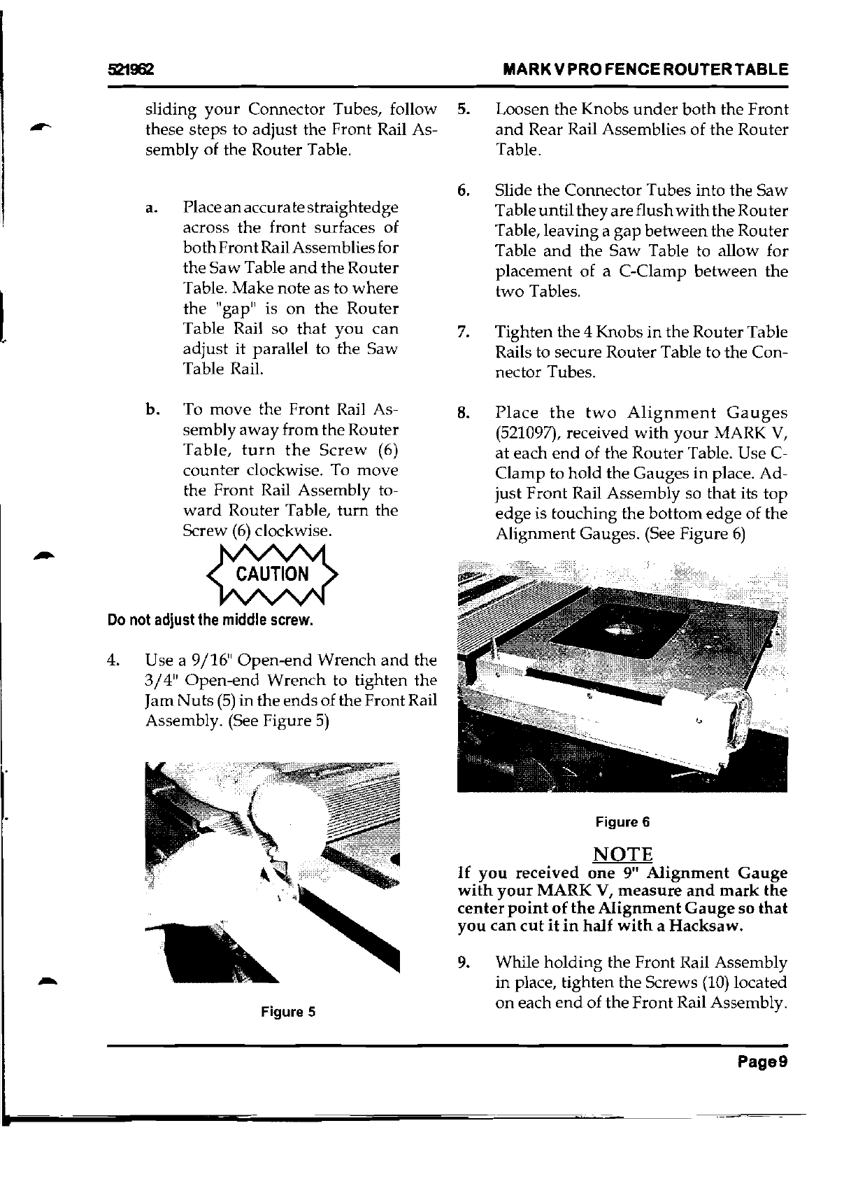
4. Use a 9/16"
Open-end
Wrench
and
the
3/4"
Open-end
Wrench
to tighten the
Jam
Nuts
(5)
in
the
ends
of
the
Front
Rail
Assembly. (See Figure
5)
Figure 5
-
5.
Loosen the Knobs
under
both
the
Front
and
Rear Rail Assemblies
of
the
Router
Table.
6.
Slide
the
Connector Tubes into the
Saw
Table
until
they
are
flush
with
the
Router
Table,
leaving
a
gap
between
the
Router
Table
and
the
Saw
Table to allow for
placement
of
a C-Clamp
between
the
two
Tables.
7.
Tighten
the
4 Knobs in the RouterTable
Rails to secure Router Table
to
the Con-
nector Tubes.
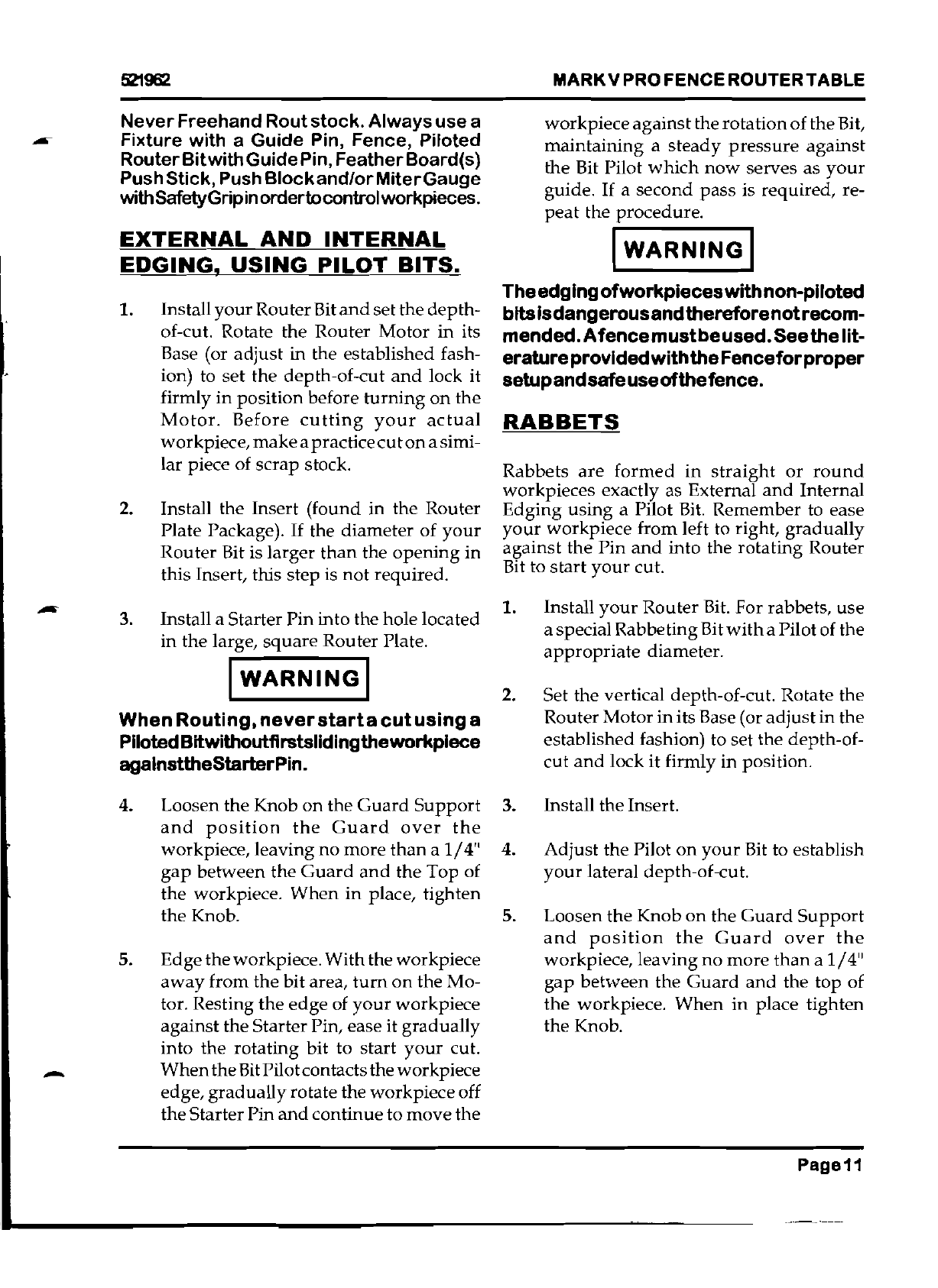
8.
Place
the
two
Alignment
Gauges
(521097), received
with
your
MARK
V,
at
each
end
of the
Router
Table. Use C-
Clamp
to
hold
the Gauges
in
place. Ad-
just
Front
Rail Assembly so
that
its
top
edge
is touching the
bottom
edge
of
the
Alignment
Gauges. (See Figure
6)
Figure 6
NOTE
If
you
received
one
9"
Alignment
Gauge
with
your
MARK
V,
measure
and
mark
the
center
point
of
the
Alignment
Gauge
so
that
you
can
cut
it
in
half
with
a
Hacksaw.
9.
While
holding
the Front Rail Assembly
in
place, tighten the Screws
(10)
located
on
each
end
of
the
Front
Rail Assembly.
Page9

MARKVPROFENCEROUTERTABLE
521962
10.
Turn
the
middle
screw (10)
either
clock-
wise
or
counterclockwise
then
tighten
the
Jam
Nut
using
the
two
open-end
wrenched.
Tighten
the
Screw.
11. Remove
the
C-Clamps
and
Alignment
gauges
and
complete
your
assembly
in-
structions
beginning
at
Step 10.
OPERATIONS
I
WARNING
I
Be
sure
toturn
off
and
unplug
the
Router
beforemakinganyadjustmentsorchanglng
RouterBlts.
1. Install
the
Router
Bit. Insert
the
Router
Bit all the
way
into
the
Collet
and
retract
about
1/8"
to
avoid
any
transi-
tion
radius
where
its
shank
becomes
larger
for
the
profile.
NOTE
The
rotary
depth-of-eut
stop
found
on
some
Plunge
Routers
may
not
allow
some
1/4"
Shank
Router
Bits to
achieve
a
full
depth-of-
cut, to
temporarily
solve
this
problem,
re-
move
the
rotary
depth-of-eut
stop.
I WARNINGl
MakesuretheRouterBitissecuredproperly
intheCollet.Loose
Bitscouldworkfreeand
causeseriousinjury.
2.
Mount
accessories.
Depending
on
the
type
of
Routing
you
are
doing,
mount
the
appropriate
Fixture, Fence(s),
andl
or
Safety Devices
such
as
Feather
Board(s) to
help
control workpiece.
3.
Set
the
depth-of-cut. Rotate the
Router
Motor
in
its Base to set
the
depth-of-
cut
and
lock it firmly in position be-
fore
turrung
it on. Before
cutting
your
actual workpiece,
make
a practice
cut
-
on
a piece of
scrap
stock.
When
some
Routers'
depth-of-cut
lock
is
loosened,
they
may
tend
to
drop
down
from
the
Router
Table.
4. Install
and
adjust
the
Guard.
I
WARNINGI
TheGuard(515704)forfreehandcutsisan
accessory
.Itnotonly
Improvessafeopera-
tionsbutalsoactsasaDustCollectionChute.
We
strongly
recommend
its
purchase
and
use.Followoperationinstructionsthrough-
outthismanualforproperuseoftheGuard.
Avoidtakingdeepcuts.Withtheexception
ofsingle-passdovetail
cuts,limitdepth-of-
cutto114"foreach
passwhenusingBits
up
to
112"diameterlnhardwood.Limitdepth- -
of-cutto3IBR -112"foreachpasswhenuslng
Bits
upto
112"dlameterinsoftwood.When
usingBitsover112"dlameter,limitdepth-of-
cutto
halftherecommendeddepthsfor112"
diameterBits.
5.
Make
the cut. After following all
setup
procedures
and
checking
to be
sure
that
everything
is
tightened
properly,
you're
ready
to
turn
on
the
Router
Motor
and
make
your
desired
cuts.
NOTE
To
prevent
dwell
marks
or
burns
on
your
workpiece,
always
work
in
a
continuous
mo-
tion
without
stopping.
Always
remember
to
raise
or
slide
your
workpiece
carefully
away
from
the
rotating
bitbefore
turning
the
motor
off.
IWARNING
I -
NeverRoutwithouttheGuardin place.
Page10
MARKVPRO
FENCE
ROUTER
TABLE
521962
Never
Freehand Routstock. Always usea workpiece
against
the
rotation
of
theBit,
Fixture with a Guide Pin, Fence, Piloted
maintaining
a
steady
pressure
against
RouterBitwithGuidePin, FeatherBoard(s) the Bit Pilot
which
now
serves as
your
PushStick, Push
Blockand/orMiterGauge
guide.
If
a
second
pass
is required, re-
with
SafetyGrip
inordertocontrolworkpieces.
peat
the procedure.
EXTERNAL
AND
INTERNAL
I
WARNING
I
EDGING,
USING
PILOT
BITS.
Theedging
of
work
pieceswithnon-piloted
1. Install
your
RouterBit
and
setthe
depth-
bitsIsdangerousandthereforenotrecom-
of-cut. Rotate the Router
Motor
in its mended.A
fence
mustbe
used.Seethelit-
Base (or
adjust
in the established fash- eratureprovided
with
theFenceforproper
ion) to
set
the depth-of-cut
and
lock it setupandsafeuseofthefence.
firmly
in
position before
turning
on
the
Motor.
Before
cutting
your
actual
RABBETS
workpiece,
make
apractice
cut
on
asimi-
lar piece of scrap stock.
Rabbets
are
formed
in
straight
or
round
workpieces exactly as External
and
Internal
2.
Install the Insert (found in the Router
Edging
using
a Pilot Bit. Remember to ease
Plate Package).
If
the
diameter
of
your
your
workpiece
from
left to right,
gradually
against the
Pin
and
into the rotating Router
Router
Bit is larger
than
the
opening
in Bit to
start
your
cut.
this Insert, this step is
not
required.
1. Install
your
Router
Bit. For rabbets,
use
3.
Install a Starter Pin into the hole located a special Rabbeting
Bitwitha
Pilot of the
in the large,
square
Router Plate.
appropriate
diameter.
I
WARNING
I
2.
Set the vertical depth-of-cut. Rotate the
When
Routing,
never
starta
cut
using
a Router
Motor
in
its Base (or
adjust
in the
PilotedBitwithoutflrstslidingtheworkpiece established fashion) to set the depth-of-
agalnsttheStarterPin. cut
and
lock
it
firmly in position.
4. Loosen the Knob
on
the
Guard
Support
3. Install the Insert.
and
position
the
Guard
over
the
workpiece, leaving
no
more
than
a
1/4"
4. Adjust the Pilot
on
your
Bit to establish
gap
between
the
Guard
and
the Top of
your
lateral depth-of-eut.
the workpiece.
When
in
place, tighten
the Knob. 5. Loosen
the
Knob
on
the
Guard
Support
and
position
the
Guard
over
the
5. Edgetheworkpiece.With the workpiece workpiece,
leaving
no
more
than
a
1/4"
away
from
the
bit area,
tum
on
the Mo-
gap
between
the
Guard
and
the
top
of
tor. Resting
the
edge
of
your
workpiece
the
workpiece.
When
in
place tighten
against the Starter Pin, ease it
gradually
the Knob.
into the
rotating
bit to
start
your
cut.
When
the
Bit
Pilotcontactstheworkpiece
-edge,
gradually
rotate the
workpiece
off
the
Starter
Pin
and
continue
to
move
the
Page11

MARKVPROFENCEROUTERTABLE
5'21962
MAINTAINING
YOUR
PRO
FENCE
ROUTER
TABLE
I
WARNING
I
BeforedolnganyMaintenanceprocedures
toyourRouterTable,besuretoturnoffand
unplug
the
Router.
ALSOremovetheRouterBitandanyother
Accessories,Fences,
or
Fixtures
that
are
mountedon
the
RouterTable.
The
maintenance
intervals
listed
here
are
based
on
normal
operation
and
assume
that
you
will
be
careful
not
to
abuse
your
Router
Table.
If
you
work
the
unit
unusually
hard,
you'll
need
to
maintain
it
more
often.
If
an
unusual
noise
or
vibration
develops,
turn
off
the
Motor
IMMEDIATELY
and
check
to
see
what
could
be
causing
the
problem.
DO
NOT
operate
the
Router
Table
again
until
you
have
corrected
the
cause
of
the
unusual
noise
or
vibration.
MAINTENANCE
SCHEDULE
As
needed
...
•
Have
Router
Bits
sharpened.
Every
5
hours
of
running
time
...
•
Clean
the
Router Table
thoroughly.
•
Check
alignments
and
adjustments.
•
Check
tightness
of all critical
hard-
ware.
Every
6
months
or
as
needed
..•
• Clean
and
wax
the
Router Table.
To
estimate
running
time,
use
this rule: The
average
woodworker
will
use
power
tools
onl\'
10% of
the
total
time
spent
in
the
shop
-
at
the most. You
may
not
use
your
Router
Table
as
much
as
other
power
tools.
If
you
work
in
your
shop
for
25
hours,
you
have
probably
logged
less
than
an
hour
of
running
-
time
on
your
Router Table.
CLEANING
As
you
work,
sawdust
will
accumulate
on
the
Router Table
and
this
residue
can
affect per-
formance.
Clean
the
Router
Table
and
Motor
with
your
Dust
Collector
or
Shop
Vacuum.
Use
the
Brush
and
CreviceTool Attachments.
After
vacuuming,
clean
all major metal
parts
of
the
Router
Table (except
the
Router
Motor)
with
mineral
spirits to
remove
all dirt,
grease
and
any
built-up
wood
pitch. Use a clean
slightly
damp
cloth to
wipe
all
residue
from
the
Guard
and
Worktable. Clean
the
Router
Motor
as
instructed
in
the
manual
that
carne
with
your
Router Motor.
WAXING
After a
thorough
cleaning,
wax
and
buff
the
TableSurface.
Apply
the
wax
sparingly,
then
-
buff
it
thoroughly.
If
you
apply
too
much
wax
or
don't
buff
it,
the
wax
will mix
with
the
sawdust,
impede
the
movement
of
parts,
and
leave
residue
on
the
stock.
Except
for
the
Laminated
Router
Table
surface,
DO
NOT
wax
or
use
solvents
on
any
other
plastic
parts.
NOTE
If
you
have
any
questions,
please
call
our
Customer
Service
Department
TollFree800-
762-7555
or
send
an
E-mail
to
visit
our
Website
atwww.shopsmith.com
e
,·
Shopsmith
n:.
~
6530 Poe Avenue
Dayton,
Ohio
45414
845512
Rev A
09/01
©
2001
Shopsmith,
Inc.
All
Rights
Reserved
Printed
In
U.S.A.
L
This manual suits for next models
1
Table of contents
Other Shopsmith Wood Router manuals


Popular Wood Router manuals by other brands

Ryobi
Ryobi RE180PL Operator's manual

SainSmart
SainSmart Genmitsu CNC Assembly instruction

XYZ Machine Tools
XYZ Machine Tools TRAK 2OP M11 Mill Safety, Installation, Maintenance, Service and Parts List

Lumberjack
Lumberjack RTS650 Safety and operating manual

DeWalt
DeWalt D26200 Original instructions

DeWalt
DeWalt DW616 instruction manual


HOLZMANN MASCHINEN
HOLZMANN MASCHINEN TFM610V operating manual

Porter-Cable
Porter-Cable 893PK instruction manual

Ergo tools
Ergo tools Pattfield E-OF 1200 operating instructions

Clarke
Clarke CR4 Operation & maintenance instructions

DeWalt
DeWalt DCW600B-CA instruction manual

Craftsman
Craftsman 320.27666 Operator's manual