short circuits SENSOR ARRAY User manual

INSTRUCTION MANUAL
SENSOR ARRAY

SENSOR ARRAY
Contents
The SENSOR ARRAY is just that, an array of sensors. The Motherboard and other Arduino
based microcontroller boards use various inputs and outputs to form functions for a device that
is of some use. The Sensor Array gives the Motherboard access to data about the surrounding
environment. This data can be saved for later, or used to trigger other actions like outputting to a
display, or triggering an alarm.
The sensors available on the Sensor Array are temperature and relative humidity via the DHT11,
sound via a microphone and amplier circuit, and light via a light dependent resistor. We have
also included a Micro SD card slot and a logic converter circuit to convert our microcontroller’s
5V logic to the 3.3V needed for the SD card’s logic.
Circuit
Assembly Instructions
Coding Basics
Projects
Component Index
4
12
20
24
26

Kit Contents
Tools Needed
1 x DHT11 Sensor
1 x Micro SD Card Slot
1 x Microphone
1 x Light Dependant Resistor
1 x LM386 Amp
1 x DIP8 Socket
3 x 100nF Ceramic Capacitors
1 x 47pF Ceramic Capacitor
5 x 10uF Electrolytic Capacitors
1 x 3.3V Regulator HT7533
3 x 2N7000 MOSFETs
9 x 10K Resistors
1 x 10 Ohm Resistor
1 x 10K Potentiometer
11 x Screw Terminals
4 x 5mm M3 Hex Screws
4 x Female/Male Standoffs
1 x Printed Circuit Board
Soldering Iron
Solder
Side Cutters
Screwdriver
Alan Key
0.3 - 0.5mm 2mm
2mm
104
3.3V
5V
U2
C4
Q3-5
R4-9
MK1 RV1
LM386
LDR
DHT22
DHT11
U3
R1
R3
R2
C2 C8
C7
C3
C5
C6
U1
+
+
+
+
+
J2
C10
Sensor Array
LDR
LDR
LDR
MIC
MIC
MIC
CLK
Dout
Din
CS
DHT
DHT
DHT
DHT
DHT
DHT
DHT
DHT
C1
R10
GND
VCC
VCC
GND
J1
473
7533-1
2N
7000
50V 10uF

4
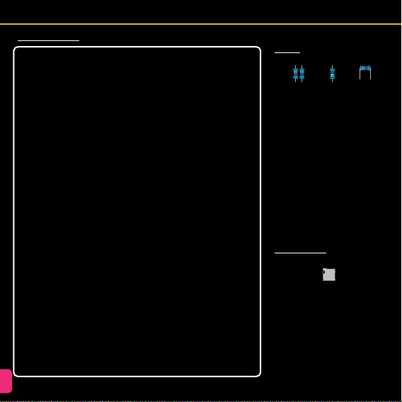
Circuit - Symbols and Designations
Copper power trace
Through hole solder pads
R
C
C
Q
RV
U
U
LDR
J
U
MK
Copper signal trace
Copper trace on back of board
Surface mount solder pads
Resistor
Ceramic capacitor
Electrolytic Capacitor
+
MOSFET
Potentiometer
LM386 Amplier
DHT11 Sensor
Light Dependant Resistor (LDR)
Micro SD Card Slot
Electret Microphone
Voltage Regulator
Mechanical hole
J
Screw terminal
Connected to GND plane
GND
Connected to VCC
+5V
PCB SCHEMATIC DESIGNATION
3
1
2
DHT22
DHT11
+
1
2
3
DAT0
VSS
CLK
VDD
CMD
DAT3/CD
DAT1
DAT2
SHIELD
1
2
3
+
CIRCUIT
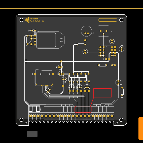
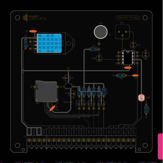
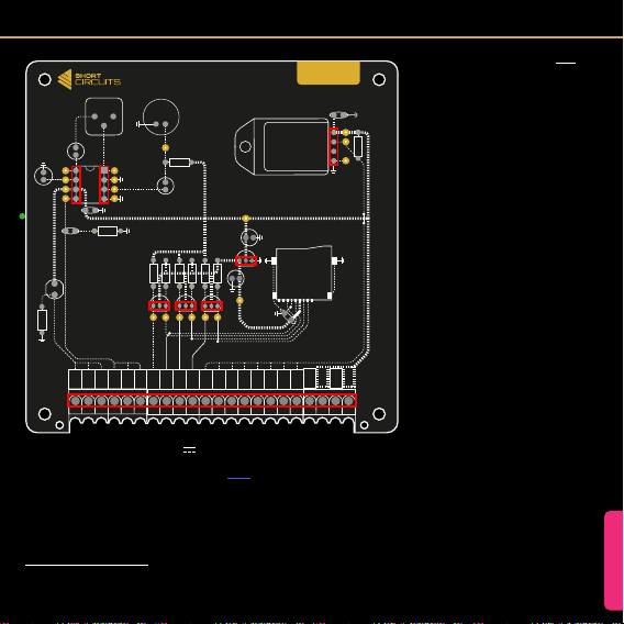
Circuit - PCB Design
Ground (GND) Copper Area On Bac
k of PCB
3.3V
5V
U2
C4
Q3-5
R4-9
MK1 RV1
LM386
LDR
DHT22
DHT11
U3
R1
R3
R2
C2 C8
C7
C3
C5
C6
U1
+
+
+
+
+
J2
C10
Sensor Array
LDR
LDR
LDR
MIC
MIC
MIC
CS
Din
Dout
CLK
DHT
DHT
DHT
DHT
DHT
DHT
DHT
DHT
C1
R10
GND
VCC
VCC
GND
J1
These labels are in the wrong
order on v1 of the PCB.
This image is correct.
6
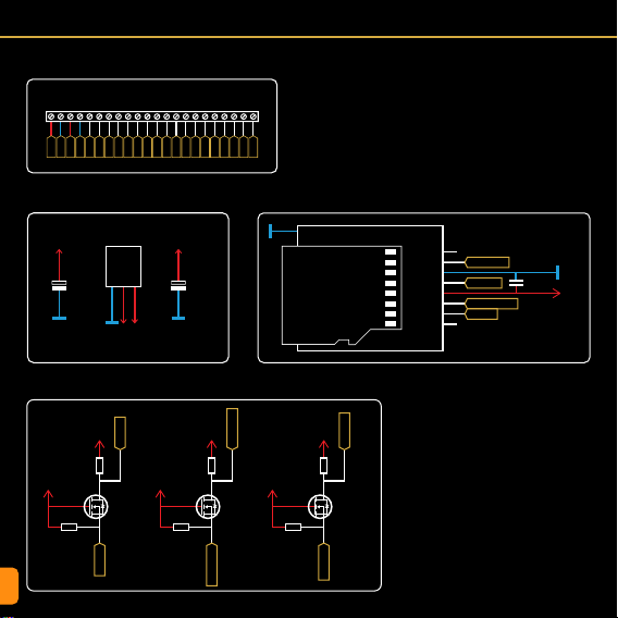
Circuit - Schematic
LDR
LDR
LDR
MIC
MIC
MIC
CS
Din
Dout
CLK
DHT
DHT
DHT
DHT
DHT
DHT
DHT
DHT
GND
VCC
GND
VCC
J1
IO
Terminal Block IO
+5V
+5V
+5V
GND
GND
C2
GND
Vin
Vout
1
2
3
1
2
3
1
2
3
1
2
3
U1
HT7533
10uF
+3.3V
+3.3V
+3.3V
GND
C3
J2
Q3
2N7000
R4
10K
R5
10K
10uF
3.3V Voltage Regulator
3.3V Logic Level Converters
Micro SD Card Slot
DAT0 DATA_OUT
CLK_3v3
DATA_IN_3v3
CS_3v3
VSS GND
CLK
VDD 3.3V
CMD
DAT3/CD
DAT1
DAT2
7
6
5
4
3
2
8
10
1
SHIELD
C10
100nF
CS_3v3
CS_5V
+5V
+3.3V
Q4
2N7000
R6
10K
R7
10K
DATA_3v3
DATA_5V
+5V
+3.3V
Q5
2N7000
R8
10K
R9
10K
CLK_3v3
CLK_5V
CIRCUIT
GND
GND
DHT11 Sensor
Light Dependant Resistor (LDR)
Microphone and Amplifier Circuit
MK1
R2
10K C6
10uF
C5
10uF
RV1
10K
U2
LM386
+
Vcc
3
2
2
4
1
1
85
7
6
BYPASSGAIN
GAIN
Vout
GND
-
R3
10Ω
C8
47pF
C4
10uF
++
+
+
+5V
+5V
+5V +5V
1
GND
IO
U3
DHT11
C1
100nF
R1
10K
VCC
2
4
DH_DATA
DH_DATA
GND
GND
GND
GND
MIC
+5V
GND
C7
100nF

8
Designation
C1, C7, C10
C2 - C6
J1
J2
Q3-5
R1, R2, R4 - R10
R3
RV1
LDR
MK1
U2
U3
Value
100nF
10uF
11 x 2 pos
Micro SD
2N7000
10K
10Ω
10K
5K - 0.5M
-52dB
LM386
DHT11
Name
Ceramic Capacitor
Electrolytic Capacitor
Screw Terminal
Micro SD Card Slot
N Channel MOSFET
Resistor THT
Resistor THT
Resistor THT
Photoresistor THT
Electret Microphone
Amplifier IC
°C/RH Sensor
Footprint / Pitch
2.54mm
2.54mm
C9 47pF Ceramic Capacitor 2.54mm
3.5mm
TO-92
7mm
7mm
3mm
2.54mm
DIP8
U1 HT7533 3.3V Regulator TO-92
Datasheet
Bill of Materials (BOM)

CIRCUIT
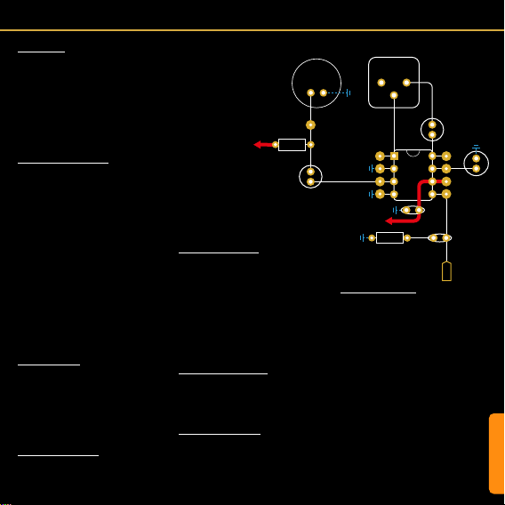
Circuit - SD Card Slot & Circuit
Micro SD Card Slot (J2)
SD Cards can be used to store informa-
tion from sensors or interactions over long
periods of time. You could use it to log the
temperature of a room over the course of a
day, or even a year. The data could then be
imported into a spreadsheet and graphs can
be made! Marvelous. This is just one exam-
ple, but there are many more.
To interface an SD card with a microcontrol-
ler running Arduino code, we need to use SPI
mode. SD cards can interface using a more
complex protocol called SDIO. This is what
mobile phones and cameras use, but it is far
too complex for a microcontroller to manage.
The labels shown on the datasheet and
those on the SD slot’s diagram above are
SDIO pins. They are there for your reference
as datasheets often only mention these. SPI
uses 4 connections; a Chip Select, 2 data
lines, and a Clock Pulse. We have labeled
these from the SD slot’s point of view (the
“slave” in the master slave analogy. See the
Motherboard Manual p29 for more info).
3.3V Voltage Regulator (U1)
SD cards run off 3.3V and so does their log-
ic. Our system runs on 5V, so we use a 3.3V
Voltage Regulator to provide the 3.3V to the
card and to the logic level converter circuitry.
We have used a 7533 for this as it provides
SD Card Motherboard / Uno
CS (Chip Select) Any Pin
Data In (MOSI) D11
Data Out (MOSI) D12
CLK (SCK) D13
+3.3V
Q3-5
2N7000
R4-9
10K
C2
10uF
U1
HT7533
+
+
J2
SD Card Slot
C10
100nF
C3
10uF
Test Point
CS_5V
DATA_IN_5V
DATA_OUT_3v3
CLK_5V
+5V
+5V
GND
GND
GND
GND
GND
DAT0
VSS
CLK
VDD
CMD
DAT3/CD
DAT1
CD
DAT2
Dout
GND
CLK
VCC
Din
SDIOSPI
CS
the 3.3V we need at a max current rating that
exceeds our requirements.
Logic Level Shifting (Q3-5, R4-9)
Logic level shifting is needed when two com-
municating devices read a High (digital 1) at
different voltages.
The SD card regards 3.3V as high, and the
Microcontroller sees anything from 3-5V
as high.
This is ne when the SD card sends a 1 to
the microcontroller, as 3.3V is still considered
High and won’t destroy anything. This is why
DATA_OUT is not converted in our circuit.
The problem arises when the microcontroller
sends a 1 (5V) to the SD card. As the card is
only rated for 3.3V, this can cause damage.
There are a few ways to achieve logic level
shifting. One method is to use two resistors
to create a voltage divider (see Resistors in
the component index). However, this method
can be somewhat unstable and only works
in one direction.
Another method uses N-Channel MOSFETs
with some pull-up resistors. This method is
stable, fast and works in both directions. SD
cards in SPI mode are limited in speed so the
2N7000 works ne. For faster switching use
a dedicated logic level MOSFET.
Arduino, and therefore the Motherboard will
only read SD or SDHC Micro SD cards up
to 32GB. These must be formatted to FAT32.
This can be done by right clicking the SD
card in an explorer window on a Windows
PC, choosing format, selecting FAT32, then
formatting.

10
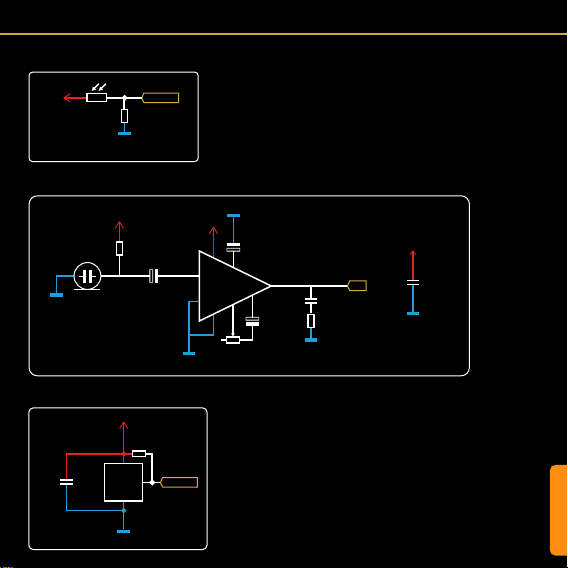
Circuit - Light Dependant Resistor (LDR)
Circuit - DHT11 Sensor
Light Dependant Resistor
A light dependent resistor is a simple device
that changes resistance depending on how
much light is hitting it. Increasing the light
intensity decreases the resistance.
Resistor (R10)
Because the LDR simply acts as a resis-
tor with varying resistance, connecting it
between 5V and the analog pin of the mi-
crocontroller won’t work. This would just
vary the current that can pass through the
resistor, but the voltage would stay pretty
much the same.
To achieve the effect we need for an accu-
rate reading on an analog pin, (a value be-
tween 0V and 5V), we need to use another
DHT11 Sensor (U3)
The DHT11 is an inexpensive sensor that
detects Temperature and Relative Humidi-
ty. It is a single data line device with some
complicated timing to deal with in the code.
Fortunately there are very useful libraries
available (“DHT Sensor Library” by Adafruit
for example) to handle all the complex stuff,
so you can concentrate on the data itself.
One of the limitations of the DHT sensors
is that they tend to interrupt anything else
that the microcontroller is controlling while
they are transferring data (a icker of the
display while the temperature is being read
for example).
The DHT11 has a more expensive cousin,
the DHT22. This sensor has a better tem-
perature and relative humidity range than the
DHT11, but this is only useful in certain situ-
ations. They are interchangeable though, so
if you nd yourself needing more range, then
swap the DHT11 out for a DHT22.
+5V
GND
GND
DHT22
DHT11
U3
DHT11/22
R1
10K
C1
100nF
DH_DATA
+5V
GND
LDR
R10
10K
LDR
Additional Components
As with any sensitive electronic device, a
bypass capacitor is always useful to smooth
out any noise. Also, the DHT11’s data line
needs to be held high according to its data-
sheet. So a 10K resistor is added between
it and Vcc.
resistor to form a voltage divider. The LDR
we are using has a resistance range some-
where between ~100 and ~0.5M (500K
ohms).
If the LDR has a lot of light shining on it, and
has a resistance value of around 100, the
analog pin would read closer to 5V (as this
is the path of least resistance) and show an
analogRead value of close to 1023.
If the LDR was in complete darkness and
had a resistance value of 500K, the path of
least resistance would be towards GND. This
would result in a value close to 0V and an
analogRead value close to 0.
If there was just enough light for the LDR to
have a resistance of 10K, we would read a
value of 2.5V and an analogRead of ~512.
These values can then be used to control
other functions. Maybe we would like to turn
on an LED when the light level gets too low,
or we could map the value to a range that we
can more easily understand, like 0-100, then
display it on a digital display as a percentage.
CIRCUIT
Circuit - Microphone & Amplifier
alternating current (AC) to pass. This removes
the DC supply voltage that powers the FET
from the AC audio signal produced by the
microphone.
LM386 Amplier IC (U2)
The LM386 is a low cost and commonly avail-
able audio power amplier. The datasheet tells
us that the amplier needs minimal external
components, has an operating current drain of
4mA, and offers voltage gains from 20 to 200.
The datasheet also provides a range of exam-
ple circuits that can help get you started. We
have used the minimum component example
with a few changes.
Bypass Capacitor (C6, C7)
Both of these capacitors help lter out any
noise from the power supply that would oth-
erwise enter the amplier.
Output Filtering (C8, R3)
C8 and R3 are used as a lter. This type of
lter is called a Boucherot Cell and is used to
dampen high frequency oscillations. It pro-
vides an escape path for high frequency oscil-
lations to prevent them building up.
Sound Sensor
This microphone and accompanying ampli-
er circuit are used as a sound sensor rather
than an audio recording device. We can use
it to listen for a clap which can trigger another
action. We can also use it to measure relative
ambient/background noise levels. With a bit of
calibration and testing this could be used to
warn you if you’re being too loud!
Electret Microphone (MK1)
An electret microphone (a type of condenser
mic) acts as a capacitor. It has two conduc-
tors separated by an insulating layer (air in this
case). When sound waves hit the rst conduc-
tor (the membrane) it vibrates. This changes
the distance between the membrane and the
other conductor. This acts as a variable ca-
pacitor that changes depending on the sound
waves hitting it.
The word “electret” is formed from the words
“electrical” and “magnet”. This is because
the membrane is permanently electrically
charged, which makes it act like a magnet.
This helps convert the capacitance to voltage,
which is then amplied inside the microphone
by a transistor.
Load Resistor (R2)
The built in Field Effect Transistor (FET) needs
to be powered for it to amplify the voltage
generated by the microphone. This is where
the load resistor comes in. This resistor, tied to
Vcc, will provide a small amount of bias for the
transistor to operate.
Coupling Capacitor (C4)
An electrolytic capacitor is used in series with
the output of the microphone. A capacitor in
series will block direct current (DC) and allow
Gain Control (RV1, C5)
Normally you would control the volume using
a pot attached to the input of the amp. This
would allow you to lower the volume from its
max (It doesn’t add volume). To enable us to
pick up background sounds and get an idea of
general ambient noise we added the pot to the
gain control rather than the input. This enables
us to change the amount of gain (increase in
volume from input to output).
The datasheet shows us an example of a static
resistor in series with a capacitor between pins
1 and 8. Different values of resistor will give
us a different gain. Without a resistor (0), the
gain is set to 200 (so when the pot is turned
fully to the right). When the pot sits at around
2K the gain is set to 20 (yes we should have
used a 2K pot...). You can experiment with the
code and the pot to get the desired effect.
+5V
+5V
GND
GND
GND
GND
GND
GND
U2
LM386
C4
10uF
MK1
RV1
10K
LM386
R3
10Ω
R2
10K
C8
47pF
C7
100nF
C5
10uF
C6
10uF
+
+
+
MIC
12
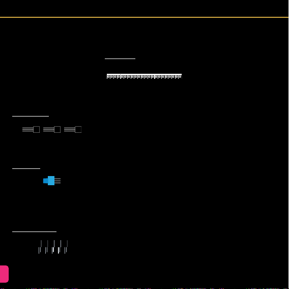
Assembly Instructions
General Soldering tips
1. ALWAYS KEEP YOUR TIP CLEAN
To ensure the soldering iron can transfer
enough heat from it to your solder/compo-
nent leg you must keep the tip clean and
shiny. A dull tip means the outside layer
of metal has oxidise. This oxidised layer
is a poor transferrer of heat. Because of
this, you will have to hold the tip against
the component for a longer period of time,
which can result in the component failing.
It’s also very frustrating.
To keep your soldering iron tip clean, wipe
it on a wet sponge or wire ball, then apply
some solder to coat it, then wipe it again.
Ideally, you should do this after every com-
ponent. At the very least, do it after every
4 components.
2. CONTACT
When soldering, make sure the tip of your
iron is making contact with both the leg of
the component and the pad on the PCB.
Apply heat to the area, then, within a sec-
ond or two, apply the solder to the point
of contact.
3. HEAT
It is better to be too hot than too cold. As
mentioned earlier, when the iron tip isn’t hot
enough, you have to hold it on longer. This
allows heat to transfer into the component
and could cause a failure. It is better to set
your soldering iron a little hot so the solder
melts instantly and ows around the leg of
the component with ease. You can start at
around 350C and adjust from there.
4. SOLDER
Leaded solder is much easier to work with,
which makes it easier to learn with. It can
be hard to nd in some countries, but can
often be ordered from China. There are po-
tential health risks, but these are very low.
Make sure you have a fan pointing away
from your work area to blow the fumes
away. Work in a well ventilated area.
Thinner is better. Working with a thick wire
of solder can get messy. Use 0.4-0.5mm
solder for more control. You will have to
feed more into the solder joint, but you
have more control when there are other
pins close by that you want to avoid. This
is essential when soldering surface mount
components and Integrated Circuits.
5. SAFETY
350C is obviously very hot. Stuff catches
re at this temperature. Skin fries. Please
be careful. Remember to turn it off when
you are nished. This will prevent a poten-
tial house re and also save your iron tip
from continued oxidation.
6. ANGLE OF ATTACK
When soldering, make sure you position
the board so that it is easy to access the
area you are working on. It is easy to make
a mistake when you are trying to maneuver
your iron into position around some obsta-
cle. You may have to spin the board 180
degrees, or make sure you have snipped
the legs off the previous component. It’s
easy to be impatient so try to plan ahead.
Resistors
Bend each leg of the resistor by 90 de-
grees, as close to the resistor as possible
(g.1). Then insert the legs into the correct
holes by nding the correct reference (R1,
R2 etc) on the board, or by using the pic-
ture on the next page as a guide. Polarity
is not important with resistors, so either
way is ne.
Hold the resistor in place with sticky tack
or tape, then ip the board over, ready for
soldering. Solder each leg by holding the
soldering iron tip to the leg and the pad,
then apply the solder to the joint. Let it ow
around the leg and create a shiny cone. Use
ush cutters to cut the legs off, then briey
hold the soldering iron to the joint to re-ow
the solder.
Micro SD Card Slot
This is by far the most difcult component
to solder in this kit. It is similar to the USB
socket in the Motherboard kit, but slightly
easier. If you would like to leave this to the
end, make sure you leave C10 to the end.
Start off by placing the SD card slot in the
correct position according to the footprint
J2. While making sure the row of pins are
lined up with the pads on the board, use
R1, R2, R4-10 R3
10K 10 g.1
J2
Micro SD Card Slot

3.3V
5V
U2
C4
Q3-5
R4-9
MK1 RV1
LM386
LDR
DHT22
DHT11
U3
R1
R3
R2
C2 C8
C7
C3
C5
C6
U1
+
+
+
+
+
J2
C10
Sensor Array
LDR
LDR
LDR
MIC
MIC
MIC
CLK
Dout
Din
CS
DHT
DHT
DHT
DHT
DHT
DHT
DHT
DHT
C1
R10
GND
VCC
VCC
GND
J1
ASSEMBLY

14
sticky tack to hold the component in place
and solder the four pads around the sides.
Apply some ux to the pins to help prevent
bridges. Now clean your tip and apply
a little solder to it. Press the tip down on
the rst pin in the row and drag away from
the pin. This should leave enough solder to
bond the pin to the pad. Try to avoid getting
any solder on the second pin. A thin tip is
good for this. Now repeat the process for
each pin.
If you accidentally bridged two or more
pins, apply more ux to the area, clean your
tip, then drag the tip between the two pins
then wipe it clean. Repeat this until you
have removed the bridge. If it isn’t working,
add more ux. If the solder isn’t liquefying
enough increase the temperature of the
iron a little. If this doesn’t help, make sure
your tip is shiny. If it isn’t, you may need to
clean it more thoroughly and add solder to
make it shiny. If the tip dulls quickly, or the
solder refuses to stick to it, your iron may
be too hot.
A video guide will be made shortly after the
manual is published.
Light Dependant Resistor (LDR)
Solder this like any other two legged
through hole component. Add some tack,
ip the board and solder the joints. This
component isn’t polarity sensitive.
LDR
Light Dependant Resistor
Ceramic Capacitors
Install the ceramic capacitors into the cor-
responding holes (C1, C7, C8, C10). They
will easily fall out, so add some sticky tack
or tape to secure them. Polarity does not
matter. Flip the board and solder the pins
to the pads, then trim and re-ow.
IC Socket (DIP-8)
We are going to solder a socket to the PCB
rather than the chip itself. We do this to
avoid heating up the IC and to enable us to
swap it out if it stops working.
Insert the socket into the area marked U2.
Pay attention to the semi-circle indicator
and match the one on the socket with the
one on the board.
Now, stick it in place and solder 1 corner
pin, then the diagonally opposite corner.
Now check alignment and whether its ush
with the board. If one corner is too high,
add pressure to it while heating the pin
underneath.
Now you can solder all the other pins know-
ing that the socket will stay exactly where it
needs to be. If you accidentally bridge two
of the pins, wipe your clean iron tip through
the center of them until they are separated.
104
104 104
C1, C7, C10 C8
100nF (0.1uF) 47pF (0.047nF)
473
U2
DIP8 Socket
U2
LM386
DHT11
The DHT11 is a simple component to sol-
der. The leads are generously spaced. Insert
the leads into the corresponding footprint
(U3). Orient the module so the holes in the
case face upwards when the module is lay-
ing at. Lay the module at and x it in place
with some tack or a bit of glue. Now solder
the pins to the pads. Snip and reow. You
can swap this out for a DHT22, available on
the usual online retail websites.
Microphone
The microphone is polarity sensitive, so
make sure the mic lines up with the foot-
print when inserted. Solder it like any other
through hole component.
3.3V Voltage Regulator (HT7533)
The HT7533 is the rst of two components
that use the TO92 form factor. TO92s can
be tricky to solder because the legs are
often close together. We have spaced the
pads out a little to make it easier. Notice
the semi-circular shape of the TO92 looking
from the top. Match this with the footprint
on the PCB.
The outer legs will spread out a little as you
U3
DHT11/DHT22
MK1
Electret Microphone
Assembly Instructions
U1
3.3V Voltage Regulator (HT7533)
7533-1
ASSEMBLY
3.3V
5V
U2
C4
Q3-5
R4-9
MK1 RV1
LM386
LDR
DHT22
DHT11
U3
R1
R3
R2
C2 C8
C7
C3
C5
C6
U1
+
+
+
+
+
J2
C10
Sensor Array
LDR
LDR
LDR
MIC
MIC
MIC
CLK
Dout
Din
CS
DHT
DHT
DHT
DHT
DHT
DHT
DHT
DHT
C1
R10
GND
VCC
VCC
GND
J1
16
Assembly Instructions
insert it into the holes. Don’t push it too
far as the legs will spread too much and
crack the black casing. Stop when there’s
a 2-3mm gap. Add sticky tack to hold in
place, ip, solder, snip and re-ow.
If you accidentally bridge two pads togeth-
er, clean your iron, re-tin the tip, then drag
the tip through the gap between the pads.
This should separate them. If it doesn’t, re-
peat the process. If your tip isn’t clean, the
solder won’t stick to the tip when you drag
it through, so make sure that tip is clean
and re-tinned.
MOSFETs (2N7000)
The 2N7000 MOSFETs are also in TO92
packages, so follow the same instructions
as the HT7533.
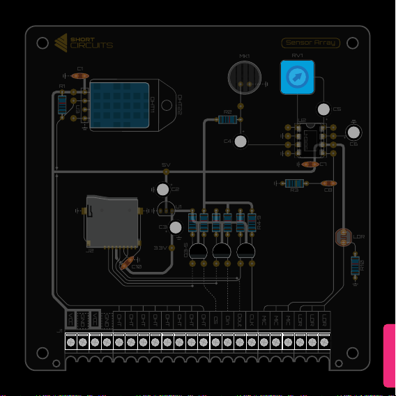
Potentiometer
Insert the legs of the Potentiometer into RV1
on the board. Hold the potentiometer with
some sticky tack and align the blue case
with the footprint. Flip the board and solder
the three pins. Snip and re-ow.
Electrolytic Capacitors
Electrolytic Caps can be soldered upright or
laying against the PCB. This kit is designed
to have them standing up. Other than being
2N
7000
2N
7000
2N
7000
Q3-5
N-Channel MOSFETs
RV1
Potentiometer
50V 10uF
50V 10uF
50V 10uF
50V 10uF
50V 10uF
C2 - C6
10uF Electrolytic Capacitors
tricky to hold in place, the caps are easy to
solder. Build up some sticky tack around
the cap to hold it in place or use some tape.
Then solder the pins as usual.
Terminal Blocks
The terminal blocks are interlocking, so
slide each of them together to make a chain
of 11. To make this line of terminal blocks t
in their holes, you may need to squeeze the
blocks together a bit.
If you are using the Rack case to display
your boards, I would suggest clipping the
legs off. These can interfere with the wires
and cause a short when they are sand-
wiched between the case and the board.
J1
CIRCUIT
3.3V
5V
U2
C4
Q3-5
R4-9
MK1 RV1
LM386
LDR
DHT22
DHT11
U3
R1
R3
R2
C2 C8
C7
C3
C5
C6
U1
+
+
+
+
+
J2
C10
Sensor Array
LDR
LDR
LDR
MIC
MIC
MIC
CLK
Dout
Din
CS
DHT
DHT
DHT
DHT
DHT
DHT
DHT
DHT
C1
R10
GND
VCC
VCC
GND
J1
ASSEMBLY

18
al, listen for a sound from your multimeter.
If there is none, excellent, you don’t have a
short between Vcc and GND. You can jump
over to the Power Test.
If you here a constant sound from your meter
when the probes are in contact with Vcc and
GND then you have a short. Check the back
of the board again for solder bridges. Focus
on the areas marked with boxes on the dia-
gram on the next page. This is where Vcc
and GND are closest.
Testing for faults
Before you power on the board, there are a
few things we need to do.
Visual Check
Firstly we need to do a visual check of the
back of the board. We are looking for solder
bridges that connect two pads that aren’t
meant to be connected. A magnifying glass
is a good tool to have when doing this. The
most likely areas for this are highlighted with
red boxes on the diagram of the back of the
PCB and the SD card slot contacts on the
front of the board.
If you see any solder bridges, bring your iron
up to temperature and drag it between the
two pads. You may have to repeat this a
few times. Make sure your iron is clean or
the solder won’t cling to it. Add ux to aid
the process.
Short Circuits
Now we need to check for short circuits (the
bad kind). If we have a short circuit some-
where on the board and we connect it to
power, or a Motherboard kit, we could dam-
age something. To check for shorts, get your
multimeter and put it in continuity mode ( )
Make sure the black cable is plugged into
the common socket and the red cable into
the red socket that also has the symbol
on it. Touch the probes together and make
sure it makes a sound. Now press the black
probe on one of the green circles indicated
in the diagram. These are all connected to
the large ground plane on the underside of
the board. Keep it held there while you press
the red probe onto one of the red circles
indicated in the diagram. The screw of the
Vcc terminal and the metal case of the SD
card slot are the most convenient. Making
sure they are both making contact with met-
Polarity
Check all the components that are polarity
dependent. In this circuit, that would be the
DHT11, Electrolytic Caps, Microphone, Volt-
age Regulator, MOSFETs and the LM386.
Powering the Board
We can now connect the Sensor Array to
the Motherboard. Connect VCC, and GND
to the Motherboards Power Out terminals.
Check that the board is receiving 4.5-5V by
3.3V
5V
U2
C4
Q3-5
R4-9
MK1 RV1
LM386
LDR
DHT22
DHT11
U3
R1
R3
R2
C2 C8
C7
C3
C5
C6
U1
+
+
+
+
+
J2
C10
Sensor Array
LDR
LDR
LDR
MIC
MIC
MIC
CLK
Dout
Din
CS
DHT
DHT
DHT
DHT
DHT
DHT
DHT
DHT
C1
R10
GND
VCC
VCC
GND
J1
ASSEMBLY
switching the multimeter to DC Voltage ( )
and putting the probes on the same points
as last time.
Check the 3.3V regulator is working by plac-
ing the black probe on a GND point and the
red probe on the test point labelled 3.3V,
below the regulator (U1)
Testing the Various Functions
Now you connect each sensor to the Moth-
erboard to test they work. Follow the “Data
Logger” connection diagram in the Project
Ideas section, then upload the test code
(HERE). Open the Serial Monitor in the Ar-
duino IDE and check the output. The text
will tell you if your SD card is inserted and
working, as well as 4 numerical outputs for
temperature, relative humidity, sound and
light. The temperature and humidity reading
should be what you expect. The microphone
reading will be all over the place. This is be-
cause the reading is a brief point on a rapid-
ly oscillating AC audio signal. To better view
this, try the test script which has been modi-
ed for use with the Serial Plotter (LINK). Up-
load this s ketch, then open the Serial Plotter
which is found in Tools on the task bar (or
press Ctrl+Shift+L). This will show you a
graph of the data over time. Play around with
the LDR by covering it or shining a light on
it. Clap to see if the microphone reading re-
sponds. If something doesn’t work, go back
and look at that part of the circuit. Check for
soldering and orientation mistakes.
Still having problems? Head over to the
forums on our website for help and sup-
port. www.shortcircuits.cc
LDR
LDR
LDR
MIC
MIC
MIC
CLK
Dout
Din
CS
DHT
DHT
DHT
DHT
DHT
DHT
DHT
DHT
C1
R10
3.3V
5V
Q3-5
R4-9
LM386
LDR
DHT22
DHT11
U3
R1
R3 C2
C8
C3
C6
J2
C10
U2
U1
+
+
+
C4
MK1
RV1
R2
C5
+
+
C7
BACK
GND
VCC
VCC
GND
J1

20
Coding Basics - DHT11
1
2
3
4
5
6
7
8
9
10
11
12
13
14
15
16
17
18
19
20
21
22
23
24
25
26
27
28
29
30
31
32
33
34
35
36
37
38
39
40
41
42
43
44
//Adding Libraries
#include <Adafruit_Sensor.h> // includes Adafruit sensor library
#include <DHT.h> // includes DHT library
#include <DHT_U.h> // includes DHT_U library
//Input Pin Variables
#dene DHTPIN 9 // Digital pin connected to the DHT sensor
#dene DHTTYPE DHT11 // Indicate the sensor type: DHT11 or DHT22
DHT_Unied dht(DHTPIN, DHTTYPE); // sets the pin and type
//Other Variables
int temp = 0; // variable to hold temperature data
int humid = 0; // variable to hold humidity data
//Void Setup - runs once at start
void setup()
{
Serial.begin(9600); // Initialise Serial Monitor
dht.begin(); // Initialise DHT Sensor
}
//Void Loop - repeats forever
void loop()
{
sensors_event_t event; // Prepares for the following events
dht.temperature().getEvent(&event); // Gets the temperature data from the DHT
temp = event.temperature; // Saves the temperature to a variable
dht.humidity().getEvent(&event); // Gets the relative humidity data from the DHT
humid = event.relative_humidity; // Saves the relative humidity to a variable
Serial.print(“Temp: “); // print text to Serial Monitor
Serial.println(temp); // print variable’s value and start a new line
Serial.print(“R.Humidity: “); // print text
Serial.println(humid); // print variable’s value and start a new line
delay(5000); // delay for 5 seconds
}
These code examples and explanations
will test all of the Sensor Array’s functions
and teach you the basics. We will cover the
following:
• Read the temperature and relative
humidity from the DHT11 sensor
• Read an analog value from the LDR
• Read and interpret values from the
microphone
• Write data to a micro SD card
As always, you will need to open the Arduino
IDE and either open a new sketch or down-
load the sketches from the links provided.
The rst sketch will handle the DHT11 sen-
sor. The DHT11 is a complex device to inter-
face with. Writing code from scratch would
be very complex. Fortunately, lots of lovely
people have written libraries to help people
write code for Arduinos and compatible
microcontroller devices like ours. Thanks
goes out to them! They make hobbyists lives
a lot easier.
Libraries can be downloaded using “the
Manage Libraries...” option under Tools in
the taskbar. You will need to add two librar-
ies to help us use the DHT11. Search for and
install the following:
• Adafruit Unied Sensor
• DHT sensor library
You can download the full sketch HERE.
Reading the comments for each line will
give you a good understanding of what is
happening. The DHT sensor code refers to
separate les downloaded with the librar-
ies. You don’t need to understand these to
write your own code, just copy the code and
adapt it as needed.


