Seco Qseven QuadMo747 x2000 User manual

QuadMo747
x2000
Qseven®Rel. 2.0 Compliant Module
with the Intel®Atom Cedarview family CPUs
and Intel®NM10 Express Chipset

QuadMo747-x2000
QuadMo747-x2000 User Manual - Rev. First Edition: 1.0 - Last Edition: 2.0 - Author: S.B. - Reviewed by G.G. Copyright © 2014 SECO S.r.l.
2
All rights reserved. All information contained in this manual is proprietary and confidential material of SECO S.r.l.
Unauthorised use, duplication, modification or disclosure of the information to a third-party by any means without prior consent of SECO S.r.l. is prohibited.
Every effort has been made to ensure the accuracy of this manual. However, SECO S.r.l. accepts no responsibility for any inaccuracies, errors or omissions herein.
SECO S.r.l. reserves the right to change precise specifications without prior notice to supply the best product possible.
For further information on this module or other SECO products, but also for getting the proper assistance for any and possible issues, please contact us using the
dedicated web form available at http://www.seco.com (registration required).
Our team will be pleased and ready to help you.
Revision
Date
Note
Rif
1.0
9th May 2013
First official release
SB
1.1
14th May 2013
Memory limitations on par. 2.2 added
SB
1.2
18th June 2013
Power consumption added
SB
1.3
6th September 2013
Manual’s heading (page 1) corrected
SB
2.0
22nd May 2014
New manual style. Minor correction. eDP support deleted
SB
REVISION HISTORY

QuadMo747-x2000
QuadMo747-x2000 User Manual - Rev. First Edition: 1.0 - Last Edition: 2.0 - Author: S.B. - Reviewed by G.G. Copyright © 2014 SECO S.r.l.
3
INDEX
INTRODUCTION.......................................................................................................................................................................... 6Chapter 1.
1.1 Warranty........................................................................................................................................................................................................................................ 7
1.2 Information and assistance............................................................................................................................................................................................................. 8
1.3 RMA number request..................................................................................................................................................................................................................... 8
1.4 Safety............................................................................................................................................................................................................................................ 9
1.5 Electrostatic Discharges.................................................................................................................................................................................................................9
1.6 RoHS compliance.......................................................................................................................................................................................................................... 9
1.7 Terminology and definitions ..........................................................................................................................................................................................................10
1.8 Reference specifications ..............................................................................................................................................................................................................12
OVERVIEW ............................................................................................................................................................................... 13Chapter 2.
2.1 Introduction..................................................................................................................................................................................................................................14
2.2 Technical Specifications...............................................................................................................................................................................................................15
2.3 Electrical Specifications................................................................................................................................................................................................................16
2.3.1 Power Rails meanings..........................................................................................................................................................................................................16
2.3.2 Power Consumption ............................................................................................................................................................................................................17
2.4 Mechanical Specifications............................................................................................................................................................................................................18
2.5 Block Diagram .............................................................................................................................................................................................................................19
OVERVIEW ............................................................................................................................................................................... 20Chapter 3.
3.1 Introduction..................................................................................................................................................................................................................................21
3.2 Connectors description................................................................................................................................................................................................................22
3.2.1 VGA Connector ...................................................................................................................................................................................................................22
3.2.2 FAN Connector....................................................................................................................................................................................................................23
3.2.3 Qseven®Connector.............................................................................................................................................................................................................24
3.2.4 BOOT Strap Signals.............................................................................................................................................................................................................43
BIOS SETUP............................................................................................................................................................................. 44Chapter 4.
4.1 Introduction..................................................................................................................................................................................................................................45
4.2 Basic configuration.......................................................................................................................................................................................................................46
4.3 Advanced configuration................................................................................................................................................................................................................47
4.3.1 RAM test execution..............................................................................................................................................................................................................47

QuadMo747-x2000
QuadMo747-x2000 User Manual - Rev. First Edition: 1.0 - Last Edition: 2.0 - Author: S.B. - Reviewed by G.G. Copyright © 2014 SECO S.r.l.
4
4.3.2 Display tests behaviour ........................................................................................................................................................................................................47
4.3.3 Wait for F1 on error ..............................................................................................................................................................................................................47
4.3.4 Ignore keyboard error........................................................................................................................................................................................................... 47
4.3.5 USB Keyboard after boot .....................................................................................................................................................................................................47
4.3.6 NumLock State at Boot........................................................................................................................................................................................................47
4.3.7 COM1 console redirection ...................................................................................................................................................................................................48
4.3.8 Peripheral reset wait.............................................................................................................................................................................................................48
4.3.9 User Option ROM................................................................................................................................................................................................................ 48
4.3.10 First / Second / Third / Fourth boot device............................................................................................................................................................................48
4.3.11 Boot video first from.............................................................................................................................................................................................................49
4.3.12 Show Graphic Logo.............................................................................................................................................................................................................49
4.3.13 Watchdog Timer time-out..................................................................................................................................................................................................... 49
4.3.14 Watchdog Timer action........................................................................................................................................................................................................ 49
4.3.15 Watchdog Timer signalling.................................................................................................................................................................................................... 49
4.4 Chipset Configuration...................................................................................................................................................................................................................50
4.4.1 PCI Express Slot 1 / Slot 2 / Slot3........................................................................................................................................................................................50
4.4.2 Internal GbE LAN .................................................................................................................................................................................................................50
4.4.3 Internal EHCI USB................................................................................................................................................................................................................50
4.4.4 Internal UHCI USB ports.......................................................................................................................................................................................................50
4.4.5 Maximum UDMA mode........................................................................................................................................................................................................ 51
4.4.6 Multi Processing ..................................................................................................................................................................................................................51
4.4.7 Default CPU frequency MHz.................................................................................................................................................................................................51
4.4.8 Execute Disable Bit..............................................................................................................................................................................................................51
4.4.9 SATA port 0.........................................................................................................................................................................................................................51
4.4.10 SATA port 1.........................................................................................................................................................................................................................51
4.4.11 LFP clock Spread Spectrum.................................................................................................................................................................................................51
4.4.12 CPU clock Spread Spectrum ...............................................................................................................................................................................................51
4.4.13 PCI INTA /INTB / INTC /INTD IRQ routing ..............................................................................................................................................................................51
4.4.14 Internal Audio.......................................................................................................................................................................................................................52
4.4.15 Internal Video Memory Mb....................................................................................................................................................................................................52
4.4.16 Video boot Device................................................................................................................................................................................................................ 52
4.4.17 Inverter Type & polarity .........................................................................................................................................................................................................52
4.4.18 Local Flat Panel....................................................................................................................................................................................................................52
4.4.19 Local Flat Panel Type...........................................................................................................................................................................................................53

QuadMo747-x2000
QuadMo747-x2000 User Manual - Rev. First Edition: 1.0 - Last Edition: 2.0 - Author: S.B. - Reviewed by G.G. Copyright © 2014 SECO S.r.l.
5
4.4.20 Local F.P. color depth..........................................................................................................................................................................................................53
4.4.21 SATA controller mode ..........................................................................................................................................................................................................53
4.4.22 PCI clock Spread Spectrum.................................................................................................................................................................................................53
4.5 Power Management.....................................................................................................................................................................................................................54
4.5.1 ACPI tables.......................................................................................................................................................................................................................... 54
4.5.2 Speed Step support ............................................................................................................................................................................................................54
4.5.3 C-States support .................................................................................................................................................................................................................54
4.5.4 UHCI (USB1.1) 0-1 wake.....................................................................................................................................................................................................54
4.5.5 UHCI (USB1.1) 2-3 wake.....................................................................................................................................................................................................54
4.5.6 UHCI (USB1.1) 4-5 wake.....................................................................................................................................................................................................54
4.5.7 UHCI (USB1.1) 6-7 wake.....................................................................................................................................................................................................54
4.5.8 LID_BTN# Configuration.......................................................................................................................................................................................................55
4.5.9 Thermal Management TM2...................................................................................................................................................................................................55
4.5.10 Active Cooling Mid Temp. / High Temp. / Mid DC (%) / High DC (%)......................................................................................................................................55
4.5.11 External FAN Duty Cycle.......................................................................................................................................................................................................55
4.5.12 Power Failure Resume Type.................................................................................................................................................................................................55
4.5.13 SMBALERT# wake capability................................................................................................................................................................................................55
4.5.14 LID Wake Configuration........................................................................................................................................................................................................55
4.6 Recovery Settings........................................................................................................................................................................................................................56
4.6.1 Allow all USB hosts off .........................................................................................................................................................................................................56
4.6.2 Hide “Control+Alt+d”Hotkey.................................................................................................................................................................................................56
4.7 IRQ Mapping ...............................................................................................................................................................................................................................57
4.7.1 IRQ Mapping .......................................................................................................................................................................................................................57
4.7.2 INT# Devices assignment.....................................................................................................................................................................................................58
Appendices.............................................................................................................................................................................. 59Chapter 5.
5.1 Thermal Design............................................................................................................................................................................................................................60
5.2 Accessories.................................................................................................................................................................................................................................63
5.2.1 VGA Adapter module M908 .................................................................................................................................................................................................63

QuadMo747-x2000
QuadMo747-x2000 User Manual - Rev. First Edition: 1.0 - Last Edition: 2.0 - Author: S.B. - Reviewed by G.G. Copyright © 2014 SECO S.r.l.
6
Chapter 1.
Warranty
Information and assistance
RMA number request
Safety
Electrostatic Discharges
RoHS compliance
Terminology and definitions
Reference specifications

QuadMo747-x2000
QuadMo747-x2000 User Manual - Rev. First Edition: 1.0 - Last Edition: 2.0 - Author: S.B. - Reviewed by G.G. Copyright © 2014 SECO S.r.l.
7
1.1Warranty
This product is subject to Italian Law Decree 24/2002, acting European Directive 1999/44/CE on matters of sale and warranties to consumers.
The warranty on this product lasts 1 year.
Under the warranty period, the Supplier guarantees the buyer assistance and service for repairing, replacing or credit of the item, at the Supplier’s own discretion.
Shipping costs that apply to non-conforming items or items that need replacement are to be paid by the customer.
Items cannot be returned unless formerly authorised by the supplier.
The authorisation is released after completing the specific form available on the web-site http://www.seco.com (RMA Online). The authorisation number for
returning the item must be put both on the packaging and on the documents shipped with the items, which have to include all the accessories in their original
packaging, with no signs of damage to, or tampering with, any returned item.
The error analysis form identifying the fault type must be completed by the customer and must accompany the returned item.
If any of the above mentioned requirements for returning the item is not satisfied, the item will be shipped back and the customer will have to pay any and all
shipping costs.
The supplier, after a technical analysis, will verify if all the requirements for which a warranty service applies are met. If the warranty cannot be applied, the Supplier
will calculate the minimum cost of this initial analysis on the item and the repair costs. Costs for replaced components will be calculated separately.
Warning!
All changes or modifications to the equipment not explicitly approved by SECO S.r.l. could impair the equipment’s and could void the warranty.

QuadMo747-x2000
QuadMo747-x2000 User Manual - Rev. First Edition: 1.0 - Last Edition: 2.0 - Author: S.B. - Reviewed by G.G. Copyright © 2014 SECO S.r.l.
8
1.2Information and assistance
What do I have to do if the product is faulty?
SECO S.r.l. offers the following services:
SECO website: visit http://www.seco.com to receive the latest information on the product. In most cases you can find useful information to solve your
problem.
SECO Sales Representative: the Sales Rep can help you in determining the exact cause of the problem and search the best solution for it.
SECO Help-Desk: contact SECO Technical Assistance. A technician is at your disposal to understand the exact origin of the problem and suggest the
correct solution.
E-mail: technical[email protected]
Fax (+39) 0575 340434
Repair centre: it is possible to send the faulty product to the SECO Repair Centre. In this case, follow this procedure:
oReturned items must be accompanied by a RMA Number. Items sent without the RMA number will be not accepted.
oReturned items must be shipped in an appropriate package. SECO is not responsible for damages caused by accidental drop, improper usage, or
customer neglect.
Note: Please have the following information before asking for technical assistance:
-Name and serial number of the product;
-Description of Customer’s peripheral connections;
-Description of Customer’s software (operating system, version, application software, etc.);
-A complete description of the problem;
-The exact words of every kind of error message encountered.
1.3RMA number request
To request a RMA number, please visit SECO’s web-site. On the home page, please select “RMA Online”and follow the procedure described.
You will receive a RMA Number within 1 working day (only for on-line RMA requests).

QuadMo747-x2000
QuadMo747-x2000 User Manual - Rev. First Edition: 1.0 - Last Edition: 2.0 - Author: S.B. - Reviewed by G.G. Copyright © 2014 SECO S.r.l.
9
Whenever handling a QuadMo747-x2000 module, ground yourself through an anti-static wrist strap. Placement of the board on an
anti-static surface is also highly recommended.
1.4Safety
The QuadMo747-x2000 module uses only extremely-low voltages.
While handling the board, please use extreme caution to avoid any kind of risk or damages to electronic components.
1.5 Electrostatic Discharges
The QuadMo747-x2000 module, like any other electronic product, is an electrostatic sensitive device: high voltages caused by static electricity could damage
some or all the devices and/or components on-board.
1.6 RoHS compliance
The QuadMo747-x2000 module is designed using RoHS compliant components and is manufactured on a lead-free production line. It is therefore fully RoHS
compliant.
Always switch the power off, and unplug the power supply unit, before handling the board and/or connecting cables or other boards.
Avoid using metallic components - like paper clips, screws and similar - near the board when connected to a power supply, to avoid
short circuits due to unwanted contacts with other board components.
If the board has become wet, never connect it to any external power supply unit or battery.
Check carefully that all cables are correctly connected and that they are not damaged.

QuadMo747-x2000
QuadMo747-x2000 User Manual - Rev. First Edition: 1.0 - Last Edition: 2.0 - Author: S.B. - Reviewed by G.G. Copyright © 2014 SECO S.r.l.
10
1.7 Terminology and definitions
ACPI Advanced Configuration and Power Interface, an open industrial standard for board’s devices configuration and power management
AHCI Advanced Host Controller Interface, a standard which defines the operations modes of SATA interface
API Application Program Interface, a set of commands and functions that can be used by programmers for writing software for specific Operating
Systems
BIOS Basic Input / Output System, the Firmware Interface that initializes the board before the OS starts loading
CEC Consumer Electronics Control, an HDMI feature which allows controlling more devices connected together by using only one remote control
CRT Cathode Ray Tube. Initially used to indicate a type of monitor, this acronym has been used over time to indicate the analog video interface used
to drive them.
DDC Display Data Channel, a kind of I2C interface for digital communication between displays and graphics processing units (GPU)
DDR Double Data Rate, a typology of memory devices which transfer data both on rising and on falling edge of the clock
DDR3 DDR, 3rd generation
DP Display Port, a type of video digital display interface
DVI Digital Visual interface, a type of video digital display interface
EHCI Enhanced Host Controller interface, a high-speed controller for USB ports, able to support USB2.0 standard
FFC/FPC Flexible Flat Cable / Flat Panel Cable
GBE Gigabit Ethernet
Gbps Gigabit per second
GND Ground
GPI/O General purpose Input/Output
HD Audio High Definition Audio, newer standard for hardware codecs developed by Intel®in 2004 for higher audio quality
HDMI High Definition Multimedia Interface, a digital audio and video interface
I2C Bus Inter-Integrated Circuit Bus, a simple serial bus consisting only on data and clock line, with multi-master capability
JTAG Joint Test Action Group, common name of IEEE1149.1 standard for testing printed circuit boards and integrated circuits through the Debug port
LPC Bus Low Pin Count Bus, a low speed interface based on a very restricted number of signals, deemed to management of legacy peripherals like
LVDS Low Voltage Differential Signalling, a standard for transferring data at very high speed using cheap twisted pairs copper cables, usually used for
video applications
Mbps Megabit per second

QuadMo747-x2000
QuadMo747-x2000 User Manual - Rev. First Edition: 1.0 - Last Edition: 2.0 - Author: S.B. - Reviewed by G.G. Copyright © 2014 SECO S.r.l.
11
MMC/eMMC MultiMedia Card / embedded MMC, another type of memory card, with same interface of SD. eMMC are the embedded version on MMC, i.e.
they are devices including both the memory controller and the flash memories on a single BGA chip
N.A. Not Applicable
N.C. Not Connected
OS Operating System
PCI-e Peripheral Component Interface Express
PSU Power Supply Unit
PWM Pulse Width Modulation
PWR Power
SATA Serial Advance Technology Attachment, a differential half duplex serial interface for Hard Disks
SD Secure Digital, a memory card type
SDHC Secure Digital Host Controller
SM Bus System Management Bus, a subset of I2C bus dedicated to communication with devices for system management, like smart battery and other
power supply-related devices
SPI Serial Peripheral Interface, a 4-Wire synchronous full-duplex serial interface which contemplates a master and one or more slaves, individually
enabled through a Chip Select line
TBM To be measured
TMDS Transition-Minimized Differential Signaling, a method for transmitting high speed serial data, normally used on DVI and HDMI interface
TTL Transistor-transistor Logic
UHCI Unified Host Controller Interface, Host Controller for USB 1.0 and 1.1 ports
USB Universal Serial Bus
V_REF Voltage reference Pin
VGA Video Graphics Array, an analog computer display standard, commonly referred also as CRT

QuadMo747-x2000
QuadMo747-x2000 User Manual - Rev. First Edition: 1.0 - Last Edition: 2.0 - Author: S.B. - Reviewed by G.G. Copyright © 2014 SECO S.r.l.
12
1.8 Reference specifications
Here below it is a list of applicable industry specifications and reference documents.
Reference
Link
ACPI
http://www.acpi.info
AHCI
http://www.intel.com/content/www/us/en/io/serial-ata/ahci.html
DDC
http://www.vesa.org
DP
http://www.vesa.org
EHCI
http://www.intel.com/content/www/us/en/io/universal-serial-bus/ehci-specification.html
Gigabit Ethernet
http://standards.ieee.org/about/get/802/802.3.html
HD Audio
http://www.intel.com/content/dam/www/public/us/en/documents/product-specifications/high-definition-audio-specification.pdf
HDMI
http://www.hdmi.org/index.aspx
I2C
http://www.nxp.com/documents/other/UM10204_v5.pdf
LPC Bus
http://www.intel.com/design/chipsets/industry/lpc.htm
LVDS
http://www.ti.com/ww/en/analog/interface/lvds.shtml
http://www.ti.com/lit/ml/snla187/snla187.pdf
MMC/eMMC
http://www.jedec.org/committees/jc-649
PCI Express
http://www.pcisig.com/specifications/pciexpress
Qseven®specifications
http://www.sget.org/uploads/media/Qseven-Spec_2.0_SGET.pdf
SATA
https://www.sata-io.org
SD Card Association
https://www.sdcard.org/home
SM Bus
http://www.smbus.org/specs
TMDS
http://www.siliconimage.com/technologies/tmds
USB 2.0 and USB OTG
http://www.usb.org/developers/docs/usb_20_070113.zip
USB 3.0
http://www.usb.org/developers/docs/usb_30_spec_070113.zip
Intel®Atom Cedarview family
http://ark.intel.com/products/codename/37505/Cedarview


QuadMo747-x2000
QuadMo747-x2000 User Manual - Rev. First Edition: 1.0 - Last Edition: 2.0 - Author: S.B. - Reviewed by G.G. Copyright © 2014 SECO S.r.l.
14
2.1Introduction
QuadMo747-x2000 is a CPU module, in Qseven®format, based on the Intel®Atom Cedarview family of CPUs, N2000 and D2000, a series of Dual Core CPU
with Hyper Threading capabilities and 64-bit instruction set.
These CPUs also integrate in a single chip the memory controller, which gives support for up to 4GB of DDR3 Memory soldered onboard (with N2600 CPU the limit
is 2GB), and a high performance 2D and 3D GPU, able to drive up to two independent display using native interfaces available on the module: HDMI, LVDS and
CRT.
The chipset of the board is Intel®NM10 Express Chipset, which completes the features of this compact and versatile board.
The board is completed with up to 4GB DDR3L directly soldered on board, and one optional SATA Flash Disk, directly accessible like any standard Hard Disk, with
up to 120GB of capacity (SATA Flash Disk is alternative to second SATA Channel on Qseven®connector).
This high level of integration allows an extremely reduced consumption of spaces, that is essential for boards with sizes so reduced as for Qseven®boards, which
offers all functionalities of standard PC boards in just 70x70mm.
Interface to the board comes through the single card edge connector, as defined by Qseven®specifications Rel. 2.0: on this connector, signals are available for
Gigabit Ethernet, one optional SD/SDIO/MMC interfaces, up to 2 x SATA Channels, up to 8 x USB 2.0 ports, 24-bit Single Channel LVDS, HDMI or multimode
Display Port interface, 3 x PCI-Express x 1 lanes, HD Audio interface, I2C, SPI and SM buses, and other features, like optional UART and SPI interfaces.
Interfacing to the board comes through a single card edge connector, as defined by Qseven®specifications Rel.2.0, where are carried out all interfaces previously
described. For external interfacing to standard devices, a carrier board with a 230-pin MXM connector is needed. This board will implement all the routing of the
interface signals to external standard connectors, as well as integration of other peripherals/devices not already included in QuadMo747-x2000 CPU module.
Please refer to following chapter for a complete list of all peripherals integrated and characteristics.

2.2Technical Specifications
CPU
Intel®Atom D2550 @1.86GHz, 1MB Cache, 10W TDP
Intel®Atom N2800 @1.86GHz, 1MB Cache, 6.5W TDP
Intel®Atom N2600 @1.6GHz, 1MB Cache, 3.5W TDP
Chipset
Intel®NM10 Express Chipset
Memory
Up to 4GB Single-Channel DDR3 / DDR3L 1066MHz soldered onboard (*)
(up to 2GB Single-Channel with N2600)
Embedded Graphics
Integrated Intel®HD Graphics controller
Dual independent display support
Video Interfaces
HDMI or Multimode Display Port interface
18/24 bit single channel LVDS interface
Additional VGA interface (optional external adapter is required)
Resolutions N2xx CPU D2550CPU
HDMI, CRT: Up to 1920x1200 Up to 1920x1200
Display Port: Up to 1600x1200 Up to 2560x1600
LVDS interface: Up to 1366x768 Up to 1440x900
Mass Storage
Up to 2 x external S-ATA channels
Optional SD / SDIO interface
Optional SATA Flash Disk soldered onboard, up to 120GB (**)
* Please notice that total amount of 4GB would be usable only with 64-bit OS. Total
amount of memory available with a 32-bit OS depends on the OS itself.
** Please consider that for HDD and Flash Disk manufacturers, 1GB = 10^9 Byte.
Some OS (like, for example, Windows) intends 1GB = 1024^3 byte, so global
capacity shown for Disk Properties will be less than expected. Please also consider
that a portion of disk capacity will be used by internal Flash Controller for Disk
management, so final capacity will be lower.
USB
Up to 8 x USB2.0 Host ports
Ethernet
Gigabit Ethernet interface
Audio
HD Audio interface
PCI Express
3 x PCI-e x1 lanes
Serial Ports
1 x Optional Serial port (TTL interface)
Other Interfaces
I2C bus
LPC Bus
SM Bus
Thermal / FAN management
Optional SPI interface
Power Management Signals
Power supply voltage: +5VDC ± 5%
Operating temperature: 0°C ÷ +60°C ***
Dimensions: 70 x70 mm (2.76”x 2.76”)
Supported Operative Systems
Microsoft®Windows XP 32-bit / Microsoft®Windows 7 32-bit
Microsoft®WES2009 32-bit / Microsoft®WES7 32-bit
Microsoft®WEC7 32-bit / Linux Ubuntu 12.04
*** Temperatures indicated are the minimum and maximum temperature that
the heatspreader / heatsink can reach in any of its parts. This means that it is
customer
’
s responsibility to use any passive cooling solution along with an
application-dependent cooling system, capable to ensure that the
heatspreader / heatsink temperature remains in the range above indicated.
Please also check paragraph 5.1.

QuadMo747-x2000
QuadMo747-x2000 User Manual - Rev. First Edition: 1.0 - Last Edition: 2.0 - Author: S.B. - Reviewed by G.G. Copyright © 2014 SECO S.r.l.
16
2.3Electrical Specifications
According to Qseven®specifications, QuadMo747-x2000 board needs to be supplied only with an external +5VDC power supply.
5 Volts standby voltage needs to be supplied for working in ATX mode.
For Real Time Clock working and CMOS memory data retention, it is also needed a backup battery voltage. All these voltages are supplied directly through card
edge fingers (see connector’s pinout).
All remaining voltages needed for board’s working are generated internally from +5V_S power rail.
2.3.1 Power Rails meanings
In all the tables contained in this manual, Power rails are named with the following meaning:
_S: Switched voltages, i.e. power rails that are active only when the board is in ACPI’s S0 (Working) state. Examples: +3.3V_S, +5V_S.
_A: Always-on voltages, i.e. power rails that are active both in ACPI’s S0 (Working), S3 (Standby) and S5 (Soft Off) state. Examples: +5V_A, +3.3V_A.
_U: unswitched ACPI S3 voltages, i.e. power rails that are active both in ACPI’s S0 (Working) and S3 (Standby) state. Examples: +1.5V_U

QuadMo747-x2000
QuadMo747-x2000 User Manual - Rev. First Edition: 1.0 - Last Edition: 2.0 - Author: S.B. - Reviewed by G.G. Copyright © 2014 SECO S.r.l.
17
2.3.2 Power Consumption
QuadMo747-x2000 module, like all Qseven®modules, needs a carrier board for its normal working. All connections with the external world come through this
carrier board, which provide also the required voltage to the board, deriving it from its power supply source.
Anyway, power consumption has been measured on +5V_S power rail that supplies the board. For this reason, the values indicated in the table below are real
power consumptions of the board, and are independent from those of the peripherals connected to the Carrier Board.
Power consumption in Suspend and Soft-Off States have been measured on +5V_A power rail. RTC power consumption has been measured on carrier board’s
backup battery when the system is not powered.
The current consumptions, written in the table of this page, have been measured using the following setup:
O.S. Windows 7 ultimate SP1
2GB DDR3
16GB SSD soldered onboard
Bios Release 1.04
USB mouse and keyboard connected
VGA display connected.
Network cable connected (except for Soft Off configuration)
Status
CPU
D2550
N2800
N2600
Idle, power saving configuration
1200mA
1035mA
837mA
OS Boot, power saving configuration
2000mA
1800mA
1540mA
Video reproduction@720p, power saving configuration
2150mA
1930mA
1590mA
Video reproduction@1080p, power saving configuration
2200mA
2020mA
1650mA
3DMark2001 benchmark, power saving configuration
2030mA
1840mA
1440mA
3DMark2005 benchmark, maximum performance
2035mA
1900mA
1470mA
Suspend to RAM (typical)
65,7mA
65,3mA
64,5mA
Soft Off (typical)
37,9mA
38mA
37,7mA
RTC Power consumption (typical)
2,6μA
2,6μA
2,6μA

QuadMo747-x2000
QuadMo747-x2000 User Manual - Rev. First Edition: 1.0 - Last Edition: 2.0 - Author: S.B. - Reviewed by G.G. Copyright © 2014 SECO S.r.l.
18
2.4 Mechanical Specifications
According to Qseven®specifications, board dimensions are: 70 x 70 mm (2.76”x 2.76”).
Printed circuit of the board is made of twelve layers, some of them are ground planes, for
disturbance rejection.
The MXM connector accommodates various connector heights for different carrier board
applications needs. Qseven®specification suggests two connector heights, 7.8mm and
7.5mm, but it is also possible to use different connector heights, also remaining compliant to
the standard.
When using different connector heights, please consider that, according to Qseven®
specifications, components placed on bottom side of QuadMo747-x2000 will have a
maximum height of 2.2mm ± 0.1. Keep this value in mind when choosing the MXM
connector’s height, if you need to place components on your carrier board in the zone below
the Qseven®module.
QuadMo747-x2000
QuadMo747-x2000 User Manual - Rev. First Edition: 1.0 - Last Edition: 2.0 - Author: S.B. - Reviewed by G.G. Copyright © 2014 SECO S.r.l.
19
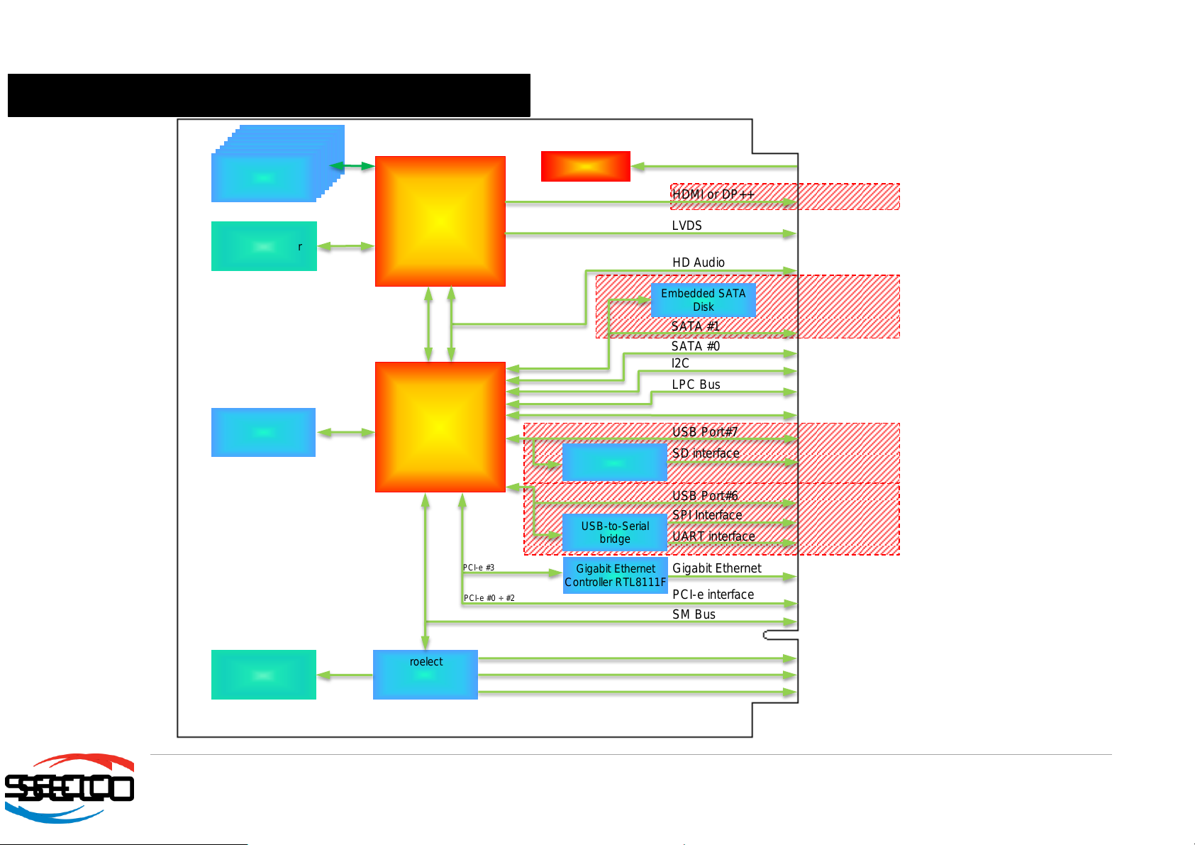
Intel®NM10
Express
Chipset
SATA #1
SATA #0
I2C
LPC Bus
SPI Interface
HD Audio
SD interface
UART interface
SM Bus
HDMI or DP++
LVDS
Gigabit Ethernet
PCI-e interface
Embedded SATA
Disk
VGA connector
Intel®Cedar
View family
CPU
Gigabit Ethernet
Controller RTL8111F
DDR3L System
Memory
PCI-e #0 ÷ #2
Power section
+5V_S, +5V_A
FACTORY
ALTERNATIVES
Power management
STMicroelectronics
STM32F100R4
microcontroller
Internal FAN
connector
Watch Dog
External FAN interface
DMI
HD Audio
USB-to-Serial
bridge
USB Port#6
FACTORY
ALTERNATIVES
PCI-e #3
SD/MMC Card
Reader
USB Port#7
FACTORY
ALTERNATIVES
USB Ports #0÷#5
FACTORY
ALTERNATIVES
SPI flash
2.5 Block Diagram

Table of contents
Other Seco Motherboard manuals


