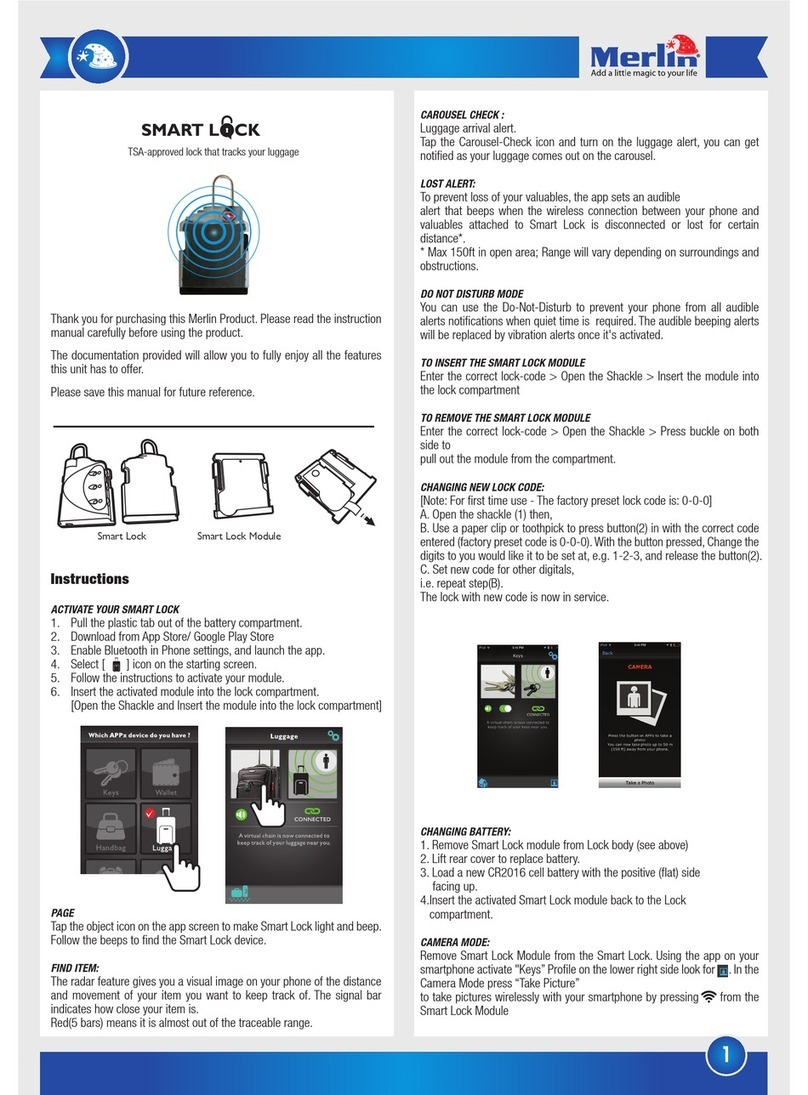
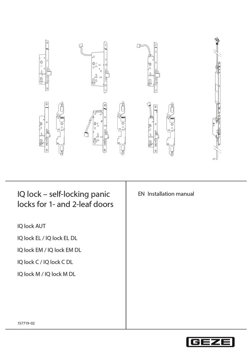
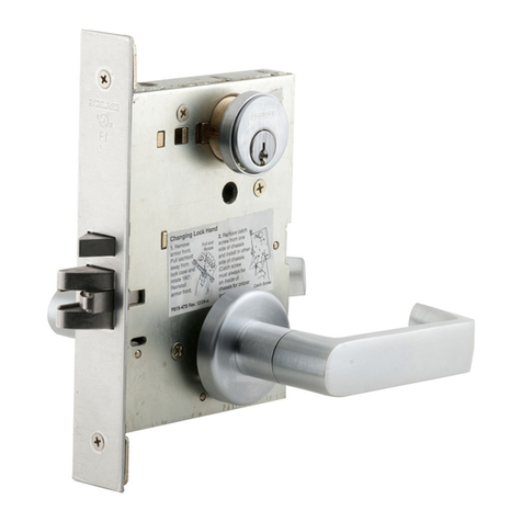
ShotLock Solo-Vault 200 Series User manual


SHOTLOCK™OWNER’S MANUAL
Thank you for purchasing a ShotLock Solo-Vault™.
Now, you can enjoy peace-of-mind knowing your personal
defense shotgun or handgun is always close, secure and
ready. When the first-responder is YOU, there may be no
time to fumble with trigger locks or open your gun safe.
With ShotLock your home defense firearm is at-the-ready
in seconds. This Owner’s Manual will guide you in the as-
sembly and installation of your Solo-Vault on a wall or in
a vehicle* putting the security you need, right where you
need it, when you need it.
* Before using this product to transport any fi rearm or mount in any type of
vehicle, make sure you are conforming to all applicable local, state and federal
laws.
* Note: Never store a fi rearm loaded.
IMMEDIATELY REGISTER YOUR VAULT
at www.shotlock.com/register
PLEASE CAREFULLY REVIEW YOUR WARRANTY:
Your ShotLock Solo-Vault is covered by a 2 Year Limited
Warranty, which will be honored from the date of purchase by
the original owner provided the ShotLock is registered within
30 days of purchase.
Now, you can enjoy peace-of-mind knowing your personal
defense shotgun or handgun is always close, secure and
Now, you can enjoy peace-of-mind knowing your personal

TABLE OF CONTENTS
Section I - ShotLock for Shotguns
Page 4 - Shotgun Solo-Vault Features
Page 5-6 - Shotgun Solo-Assembly
Page 7 - Shotgun Solo-Vault Parts List
Page 7 - Mounting Your Shotgun Solo-Vault
Section II - ShotLock for Handguns
Page 8 - Handgun Solo-Vault Features
Page 9 - Handgun Solo-Vault Parts List
Page 9 - Mounting Your Handgun Solo-Vault
Section III - Locks and Lock Operation
Page 10-13 - M-Series Lock (Mechanical)
Page 14-17 - E-Series Lock (Electrical)
Section IV - Warranty/Contact Information
Page 18 - Warranty Information
Page 19 - Notes
Back Cover - Contact Information

SHOTGUN SOLO-VAULT TM
FEATURES
• Accommodates left and right
handed shotguns.
• Secures most pump, semi-auto,
double barrel, side by side and
over/under shotguns.
• Will fit some pistol grip
(pump) shotguns.
• Flanged, no pry lid with dual
internal locking hooks.
• Military grade 14 gauge
steel construction.
• Exterior Dimensions:
7.5” x 5.75” x 2.25”
• Interior Dimensions:
7.25” x 3.875” x 2”
SEE PAGES 10-13
for the M-Series Lock.
(Mechanical)
SEE PAGES 14-17
for the E-Series Lock.
(Electrical)
4

ASSEMBLY FOR SEMI-AUTO AND
OVER/UNDER SHOTGUNS
ASSEMBLY FOR SEMI-AUTO AND
ASSEMBLY FOR SEMI-AUTO AND
ASSEMBLY FOR SEMI-AUTO AND
ASSEMBLY FOR SEMI-AUTO AND
OVER/UNDER SHOTGUNS
OVER/UNDER SHOTGUNS
OVER/UNDER SHOTGUNS
OVER/UNDER SHOTGUNS
OVER/UNDER SHOTGUNS
OVER/UNDER SHOTGUNS
OVER/UNDER SHOTGUNS
OVER/UNDER SHOTGUNS
OVER/UNDER SHOTGUNS
OVER/UNDER SHOTGUNS
1. Lay vault down either left or right opening, as preferred.
2. Lay shotgun down inside vault with bolt, handle pointing up and
position Trigger Guard Blocks snugly around trigger assembly.
3. When action is closed, bolt handle should extend outside the vault
through the door opening, and as close as possible to the top of
the door.
4. When action is open, handle will protrude through the hole in
the door.
5. Trace the positions of the Trigger Guard Blocks onto the Foam,
then cut Foam Bed Liners to fi t around Trigger Guard Blocks.
6. Using M5x14mm screws attach Trigger Guard Blocks to securely
confi ne trigger assembly inside vault.
7. Insert Foam Bed Liner.
3
2
4
5
6
5
* The second piece of foam is a backup.

ASSEMBLY FOR
PUMP SHOTGUNS
1. Lay vault down either left or right opening, as preferred.
2. For right-handed shotguns, Pump Ejection Port Hanger
will be mounted top right. For left-handed shotguns, Pump
Ejection Port Hanger will be mounted top left.
3. Trace the position of the Pump Ejection Port Hanger onto
the Foam Bed Liner, then cut Foam Bed Liner to fi t around
Hanger.
4. Using M5x14mm screws attach Pump Ejection Port Hanger
to inside of vault.
5. Insert Foam Bed Liner.
6. With action open, place ejection port over Pump Ejection
Port Hanger.
Pump Ejection
Port Hanger
6
PUMP SHOTGUNSPUMP SHOTGUNS
1.
2.
3.
4.
5.
6.
6
3
4
2
* The second piece of foam is a backup.

SHOTGUN
SOLO-VAULT
PARTS
1
2
34
56
8
7
7
Shotgun Solo-Vault Body
Foam Bed Liners (2)
Adjustable Trigger
Guard Blocks (2)
Pump Ejection
Port Hanger (1)
M5x14mm Trigger
Block Mounting
Screws (4)
#14 Flat Head Phillips
Vault Mounting Screws (4)
Override Key (3)
E-SERIES ONLY:
-Emergency
Battery Backup
Kit (1)
-Allen Wrench (1)
-AA Batteries (4)
MOUNTING YOUR SHOTGUN SOLO-VAULT
1. Securely attach vault in conve-
nient location with the provided
Vault Mounting Screws. *
2. Pump Ejection Port Hanger may
also be mounted on opposite side
to reverse the direction the
door opens.
Don’t forget, adhere logo sticker to front.
Don’t forget, adhere logo sticker to front.
Don’t forget, adhere logo sticker to front.
Don’t forget, adhere logo sticker to front.
* PLEASE NOTE : In order to be compliant with California DOJ standards, the
Shotgun Solo-Vault must be mounted to a surface using the Mounting Screws, and the
fi rearm must be secured using the Ejection Port Hanger or Trigger Blocks. The exposed
screws on the back should not be accessible once the device is mounted and locked.
* Owner’s Manual
* ShotLock Sticker

HANDGUN SOLO-VAULT TM
SEE PAGES 10-13
For the M-Series Lock.
(Mechanical)
SEE PAGES 14-17
For the E-Series Lock.
(Electrical)
FEATURES
• Secures up to a 1911 sized full
framed handgun.
• Mounts on a wall, flat surface or
in a vehicle.
• Carrying handle and cable holes
for ultra portability. (Cable not
included).
• Military grade 14 gauge
steel construction.
• Flanged, no pry lid with dual
locking hooks.
• Exterior Dimensions:
7.5” x 5.75” x 2.25”
• Interior Dimensions:
7.25” x 3.875” x 2”
8

MOUNTING YOUR HANDGUN
SOLO-VAULT
1. Securely attach Handgun Solo-Vault in
convenient location using 4 mounting
screws.
2. You may also secure your Handgun
Solo-Vault by threading a heavy 5/16”
locking cable through the provided
port holes.
• Be sure to adhere the ShotLock logo to the
front side of your Handgun Solo-Vault.
Your Handgun
Solo-Vault can
mount virtually
anywhere.
9
#14 Flat Head Phillips
Vault Mounting Screws (4)
Override Key (3)
2
4
3
1
E-SERIES ONLY:
-Emergency
Battery Backup
Kit (1)
-Allen Wrench (1)
-AA Batteries (4)

M-SERIES LOCK (mechanical)
FEATURES
• All mechanical operation, no
batteries or wires.
• Over 1500 customizable push
button combinations.
• Easily change your combination.
• Tamper proof lock clutch. Knob
will spin when an incorrect
combination is entered.
• Built in Key Override for backup
access. (3 extra keys)
• 2 year limited warranty.
Easily change your combination.
RECORD YOUR NEW
COMBINATION AND KEEP
IT IN A SAFE PLACE
* Pick any 4 numbers (no duplicates)
If you lose your combination and all three override
keys, contact customer service at 800.852.0400
10

OPERATING THE M-SERIES
MECHANICAL LOCK
TO OPEN WITH FACTORY CODE: Factory combination is 1 - 2 -7 - 8.
Before setting the new combination, we recommend recording your new pass-
word in the provided space on page 10.
• Changing your combination can usually be done in less than fi ve minutes.
Please reference pages 12-13 to change your electric lock combination.
Enter in your four
digit combination
code, (each punch
should provide a
distinct “click”).
Ensure the locking
knob is in the “Open”
position and then close
the door.
Insert your key into
the lock and turn to
unlock position.
Then turn the locking
knob into the
“Open” position.
Turn the locking knob
to the “Open” position
and then proceed to
open the door.
While holding the
door closed, turn the
locking knob to the
“Lock” position.
When fi nished, close the
door, and turn locking
knob to “Lock” position.
Return key into lock
position, and then
remove the key.
UNLOCK
LOCK
KEY OVERRIDE
UNLOCK
LOCK
11

CHANGING COMBINATION (M-SERIES LOCK)
Introduction: Changing your combination can usually be done in less than fi ve minutes.
Of the 8 numbers possible, 4 numbers will need to be used for your custom combination.
Factory combination is 1 - 2 - 7 - 8. Also, before setting the new combination, we recommend
you record the new four digit code on page 10 of this manual.
GETTING STARTED
1. Remove both Phillips screws (one on each side of the
box) and slide the metal cover vertically.
2. Pull the lock module out as shown (no hardware
disassembly required).
3. Once the combination pin box is removed, use your
thumb to push the center gray slide and either the
left or right unlock button to release the spring
pressure, on all 8 pins (buttons facing up).
4. While holding these two buttons, pull out the A, B, C,
and D pins (stamped on side of the pins).
• These four pins are your combination pins.
Place the four pins on a table and release the
thumb pressure on the two buttons.
• All remaining pins are blanks, and will always
be located in the slots not associated with the
combination. All blank pins are identical and
can be inserted into any (non-combination)
locations.
SETTING NEW COMBINATION
5. Any new combination you pick will always need to
be sequential when you enter your combination to
unlock your ShotLock. For example : when entering
the numbers out of your chosen sequence, it will
not open.
6. To obtain the correct sequence with your new
combination, we suggest to record your code in the
designated box on page 10.
2
3
4
12

7
8
11
10
7. To insert the pins back into the module, press the
two slides at the same time (see step 3). Proceed to
insert the four pins into the correct locations.
• Any blank that may be still in one of these
slots, can be removed and placed into any
other location.
• Each time you insert a pin, gently push the
pin all the way in to insure it is seated into
its location.
8. Once fi nished, and all eight pins are installed,
release your thumb, and gently press all eight
pins to insure each snap in and out smoothly. If a
pin does not, simply repeat steps 3 and 7 for that
individual pin.
9. Once your new combination is complete, simply
set the module back into its location . If the module
seats into its three location pins, it will snap in
place, and stay put in its cradle. If the module
won’t stay in place, put back into the cradle until
you feel it snap into place.
10. Slide the metal cover back into place. Place special
attention and have the cover follow the vertical
guide rails.
• If the cover won’t go on easily, that usually
means your lock module is not snapped into
proper place.
11. Insert the two Phillips screws back into place, and
now you are done!
12. Once installed, we recommend trying your new
combination with the ShotLock door still open, in
case you have placed a pin incorrectly by accident
and the combination does not work as planned.
If this happens, just remove again, and follow the
previous instructions.
13

E-SERIES LOCK (electrical)
FEATURES
• Over 1.3 million customizable
button combinations.
• Tamper proof lock clutch. Knob
will spin when an incorrect
combination is entered.
• Built in Key Override for backup
access. (3 extra keys)
• Easy combination change
procedures.
• Emergency Battery Backup Kit.
• 2 year limited warranty.
• Low battery indicator.
Low battery indicator.
RECORD YOUR NEW
COMBINATION AND KEEP
IT IN A SAFE PLACE
* Use between 4 and 10 digits / numbers can be used
more than once.
If you lose your combination, keys, and Emergency
Battery Backup kit, please contact customer service
at 800.852.0400
14

OPERATING THE E-SERIES
ELECTRICAL LOCK
Punch in your multi-
digit code, then press
OK. You will hear a
single short beep if the
code was successful.
Ensure the locking
knob is in the “Open”
position and then close
the door.
Insert your key into
the lock and turn to
unlock position.
Then turn the
locking knob into the
“Open” position.
Turn the locking knob
to the “Open” position
and proceed to open
the door.
While holding the
door closed, turn the
locking knob to the
“Lock” position.
When fi nished, close the
door, and turn locking
knob to “Lock” position.
Return key into lock
position, and then
remove the key.
UNLOCK
LOCK
KEY OVERRIDE
Punch in your multi-
UNLOCK
LOCK
Turn the locking knob
TO OPEN FOR THE FIRST TIME: Batteries are included but not installed. You will
need to access the ShotLock using the Key Override to install the batteries initially.
TO OPEN WITH FACTORY CODE: Factory combination is 1 - 2 - 3 - 4 plus “OK”. You
will hear a single short beep if the combination was successful. A short double beep indi-
cates a wrong combination was entered. To change the combination please see page 16.
TO CHANGE THE BATTERIES: A short triple beep indicates low battery power. To
change the batteries, fi rst open the ShotLock to access the interior battery cover plate.
Use the provided Allen Wrench to remove the battery cover plate, and replace the 4 AA
batteries. Reattach the battery cover plate.
TO DISABLE THE BEEP: If you wish to turn off the beeps emitted by pressing a but-
ton, simply press and hold “1” for 5 seconds. To re-enable the beeps, press and hold “2” for
5 seconds.
Insert your key into
the lock and turn to
unlock position.
Then turn the
locking knob into the
“Open” position.
Punch in your multi-
digit code, then press
OK. You will hear a
single short beep if the
code was successful.
Punch in your multi-
Ensure the locking
knob is in the “Open”
position and then close
the door.
Turn the locking knob
to the “Open” position
and proceed to open
the door.
UNLOCK
LOCK
Turn the locking knob
position and then close
While holding the
door closed, turn the
locking knob to the
“Lock” position.
When fi nished, close the
door, and turn locking
knob to “Lock” position.
Return key into lock
position, and then
remove the key.
15

CHANGING COMBINATION (E-SERIES LOCK)
Introduction: Changing your combination is easy and takes less than a minute.
The E-series lock off ers over 1 million combination possibilities. Your code can be anywhere
from 4 digits up to 10 digits in length. Also, before setting the new combination, we recommend
you record the new combination code on page 14 of this manual.
GETTING STARTED
1. Open your ShotLock with your
current electronic combination, OR
by using the Key Override.
2. Make sure the locking knob is in the
“OPEN” position.
3. Enter your new combination (4 to 10
digits) and press and HOLD the OK
Key until a short beep is heard.
4. Quickly enter your new combina-
tion again, and press and HOLD the
OK Key again until a LONG beep
is heard.
5. The long beep CONFIRMS your new
combination. DOUBLE beep means
an ERROR, and start over at Num-
ber 4 (above).
• Any new combination you pick will always
need to be sequential when you enter your
combination to unlock your ShotLock. For
example : when entering the numbers out of
your chosen sequence, it will not open.
• To obtain the correct sequence with your new
combination, we suggest you record your code
in the designated box on page 14.
4
2
3
16

If all three of the provided keys have been misplaced, and the internal battery has
expired, ShotLock provides another opportunity for you to get your ShotLock open.
OPERATING THE EMERGENCY
BATTERY BACKUP
1. Each E-Series lock comes with an
Emergency Battery Backup Kit.
Four AA batteries are required, but
not included.
2. Install batteries into your included
Emergency Battery Backup Kit.
3. Plug the pin into the DC hole on the
top of the faceplate.
• This will energize the internal electronics
allowing you to enter your combination to
access the ShotLock.
4. While keeping the pin in the DC hole,
push your combination and the “OK
key. This will activate the unlock
feature. Proceed to open your Shot-
Lock Solo-Vault.
5. Finally, be sure to open the battery
plate and replace the expired batteries
(four AA) for future use.
• We recommend changing batteries
annually.
1
EMERGENCY BATTERY BACKUP
INSTRUCTIONS (E-SERIES LOCK)
3
4
17

LIABILITY DISCLAIMER AND FULL WARRANTY
ShotLock LLC guarantees to the original purchaser that the ShotLock Solo-Vault™ is free
from defects in material and workmanship for a period of 2 years (24 months) from the
date of purchase.
In the event of any defects in material or workmanship, ShotLock’s sole liability shall be to
repair or replace the defective product or components, at its sole discretion. ShotLock may
replace the unit with a new or refurbished unit, which is guaranteed by ShotLock. Allow up
to 6 to 8 weeks for repair or replacements.
The conditions and extent of the Warranty are as follows:
- If it becomes necessary to send the product to ShotLock, the product must be shipped
in its original carton or equivalent, fully insured with all shipping charges prepaid. Shot-
Lock is not responsible for any loss or damage incurred in shipping.
- Advance return authorization is required from our Customer Service Department.
800-852-0400. If service on the product is required during the warranty period, obtain the
authorization and send your product, together with a copy of your sales receipt with date
of purchase (required), name, street, daytime telephone number and (if available) e-mail
address to:
ShotLock LLC
P.O. Box 307 / 215 Township Street
Sedro-Woolley, WA 98284-0307
- This Warranty is void if (except for law enforcement personnel) the product is used for
commercial purposes, or if service has been performed on the product by anyone other
than ShotLock.
- This Warranty does not apply to any product that has been altered, misused, neglected
or which has been used other than in accordance with the furnished instructions.
- Except to the extent prohibited by law, all implied warranties are disclaimed, including
fitness for a particular purpose, merchantability and course of dealing or trade, and in no
event shall they have greater duration than the warranty period set forth above.
- Under no circumstances shall ShotLock or its vendors be liable for any loss or any
damage, injury or death, or direct, incidental, consequential or punitive damages arising
out of or attributable to the malfunction, use or inability to use (including but not limited
to because of a lost, misplaced, stolen or forgotten code) the product. Some states do not
allow limitations on how long an implied warranty lasts or limitations or incidental or
consequential damages, so THE ABOVE LIMITATIONS OR EXCLUSIONS MAY NOT AP-
PLY TO YOU. THIS WARRANTY GIVES YOU SPECIFIC LEGAL RIGHTS, AND YOU MAY
ALSO HAVE OTHER RIGHTS, WHICH VARY FROM STATE TO STATE.
18

NOTES
19

CUSTOMER SERVICE
For all Customer Service questions call us toll free:
P: 800-852.0400 F: 360-855-2239
Or write:
ShotLock
P.O. Box 307/215 Township Street
Sedro-Woolley, WA 98284-0307
Or visit our website: www.shotlock.com
Each 200 Series ShotLock Solo-Vault covered in this Owner’s Manual is a
California-approved fi rearm safety device that meet the requirements of Penal Code
section 23655 and the regulations issued thereunder.
SAFETY WARNING: Firearms are inherently dangerous and use of this product requires care and attention. Weapon storage,
security and use are your personal responsibilities. Since ShotLock has no control over the fi rearm you use, the ammunition
you carry and the manner in which you use the fi rearm or ammunition, it disclaims all related responsibility and liability.
Your use of our product is at your own risk.
Using appropriate safety precautions with a loaded fi rearm is the sole responsibility of the person(s) using or handling the
product. The user takes full responsibility for careless, inappropriate, improper, incorrect or negligent use of this product or
related fi rearm. ShotLock and its vendors are not responsible for the misuse or mishandling of this product or of any weapon
in connection with the product, nor for any personal injury, death or damage to you, or to anyone else, to any property or your
weapon or anyone else.
Each 200 Series ShotLock Solo-Vault covered in this Owner’s Manual is a
Table of contents
