SHOTO SDA10-49100 User manual

Home power Lithium-Ion Battery
Product Manual
(V1.0)
Shuangdeng Group Co., Ltd

This manual introduces SDA10-48100 from Shoto. Please read this manual before
you to install the batteryand follow the instruction carefully during the installation
process.Any confusion,please contact Shoto immediately for advice and
clarification.
Contents
1. Safety Precautions ....................................................................................................................4
1.1、Reminding ......................................................................................................................4
1.2 、Warning ..........................................................................................................................5
1.2.1、Before Using ...........................................................................................................5
1.2.2、In Using.................................................................................................................... 5
2. Product advantages...................................................................................................................5
3. Specifications ............................................................................................................................6
4. Systempanel instructions........................................................................................................7
4.1、The main information of panel battery products as follows: ..................................7
4.2、Communication interface..............................................................................................8
4.2.1、Cascade communication interface.......................................................................8
4.2.2、Communication wire ........................................................................................... 10
4.2.3、CAN........................................................................................................................11
4.2.4、Power Terminals ..................................................................................................11
4.2.5、LED Status Indicators.........................................................................................12
4.2.5.4、Flashing instructions ........................................................................................13
4.2.5.5、Status indication................................................................................................13
5. Safe handling of lithium batteries Guide ............................................................................14
5.1、Schematic Diagram of Solution.................................................................................14
5.2、Explanation of Symbol................................................................................................14
5.3、Tools............................................................................................................................... 15

5.4、NOTE.............................................................................................................................15
5.5、Safety Gear....................................................................................................................15
5.6、Installation....................................................................................................................16
5.6.1、Package Items .......................................................................................................16
5.6.2、Installation Location............................................................................................19
6. Trouble Shooting Steps..........................................................................................................20
6.1、Problem determination based on:..............................................................................20
6.2、Preliminary determination steps:...............................................................................20
6.3、The battery cannot be charged or discharged.......................................................... 21
7. Emergency Situations ............................................................................................................21

1. Safety Precautions
1.1、Reminding
1)It is very important and necessary toread the user manual carefully (in the
accessories)before installing or using battery. Failure to do so or to follow any of the
instructions or warnings in this document can result in electrical shock, serious injury, or
death, or can damage battery,potentially rendering it inoperable.
2)It is strictly forbidden to immerse thebattery in water or rain.
3)Prohibit using and shelving the battery beside the high temperature source.
4)Please usethe module according to the charge and dischargeparameters specified
in this manual.
5)It is prohibited to connect thebattery and AC power directly.
6)Forbid discarding the battery into fire or heater.
7)Forbid breaking up the battery and its part.
8)Forbid to rap, stomp and throw thebattery.
9)Even if the grid is cut off, the batterymodule still has the voltageoutput,please
take care to avoid electric shock or shortcircuit when using battery module.
10)If the batteryis stored for long time, it is required to charge them every six
months, and the SOC shouldbe no less than 90%.Battery needs to be recharged within
12 hours,after fully discharged.
11)Do not expose cable outside.
12)All the battery terminals must be disconnected for maintenance.
13)Do not connect battery with PV solar wiring directly.
14)Please contactthe supplier within 48 hours if there is something abnormal.
15)In areas with poor environmental conditions,effective protective measures must
be taken for battery module, such as good grouding, sunshading board,rain cabinet and
dustscreen,to avoid lightning, rain, snow, high temperature, dust damage battery
module and impact battery life.
16)For being used in high temperature areas, the battery must be used in cabinets
with corresponding heat dissipation equipment (fans or air conditioners). In low
temperature areas, the battery must be used in cabinets with corresponding heating
equipment (heating plates or air conditioners). In coastalareas, the batterymust be used
in a cabinet with the corresponding salt spray protection capability.
17)Unless otherwise specified, the charging and discharging current for the battery
module and battery module is recommended to be set at 0.5C3.
18)Please read the product manual carefully before installation and application,The
warranty claims are excluded for direct or indirect damage due to items above.

1.2 、Warning
1.2.1、Before Using
1)After unboxing, please check product and packing list first, please read the
product manual carefully before installation and application,if product is damaged or
lack of parts, please contact with the local retailer;
2)It is prohibited to connectthe battery and AC power directly;
3)Before installation, the cable must not be reversed and make sure the battery is in
the turned-off mode;
4)Wiring must be correct, do notmistake the positive and negative cables, and
ensureno shortcircuit with the external device;
5)The battery please DO NOT connect battery in series;
6)Battery systemmust be well groundedand the resistancemust be less than 1;
7)Please ensured the electrical parameters of battery systemare compatible to
related equipment;
8)Keep thebattery away from water and fire.
1.2.2、In Using
1)If the battery systemneeds to be moved or repaired, the power must be cut off
and thebattery is completely shutdown;
2)It is prohibited to putthe batteries working with faulty or incompatible inverter;
3)In caseof fire, only dry powder fire extinguisher can be used,liquid fire
extinguishers are prohibited.
4)It is forbidden to connectthebattery with different types of battery.
2. Product advantages
1)The battery positive electrode is made of LFP, which has long cycling life and
good safety.
2)The battery module adopts the high-performance BMS, which has the protective
functions of current, voltage and temperature etc..
3)The systemcan seamlessly turn on after thepublic electricity fails.
4)Adopting theself-cooling method, the systemhas extremely low noise.
5)Good temperature characteristics : working environment temperature can reach
-20~+50℃(Charging -5~45℃; discharging -20~50℃,recommended
temperature:+15~+35℃).
6)LFP battery has excellent rate dischargeperformance, which enables LFP battery
with small capacity to meet large current discharge requirements.

3.Specifications
Model
SDA10-48100
Nominal Capacity(kWh)
5.12
Depth of Charge
90%
Usable Capacity (Wh)
4.60
Charge Voltage (V)
54.0-56.4
Discharge Voltage (V)
45.0-48.0
Nominal Voltage (V)
51.2
Charge/Discharge Current(A)
Recommend 50(0.5C)
Max 100 (1C)
Communication Port
RS485 & CAN
Weight (Kg)
41±1Kg
Dimensions (W*H*D)mm
442mm±2mm*133mm±2mm*420±2mm
OperatingTempature(℃)
Charge:-5℃~+45℃
Discharge:-20℃~+50℃
RecommendOperatingTempature(℃)
Charge:+15℃~+35℃
Discharge:+15℃~+35℃
Storage:-20℃~+35℃
Humidity
5%-95%
Altitude
≤4000m
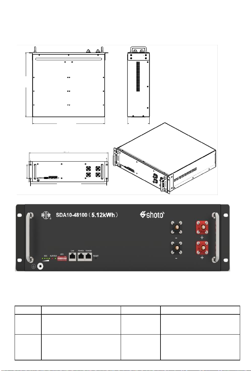
4.System panel instructions
Pic.1 SDA10-48100 Schematic of lithium iron battery system panel
4.1、The main information of panel battery products as follows:
Table 1 SDA10-48100The mainpanel detailsof lithium iron batterysystem
Number
Designation
loge
Descriptions
1
Capacity indicator
SOC
4 green lights,greenLEDstoshow
the battery’s current capacity, each
light indicates25%capacity.
2
Stand by lamp
ALM
1 redlight, redLED flashing to
showthe battery hasalarm, and
lightingto showthe batteryisunder
protection.
1 2 3 4 5 6 7 8
11
9
10
420
442
133
484
89
466.4
133

Number
Designation
loge
Descriptions
3
Communication running lights
RUN
1 green light,runninglights
4
ADD switch
ADD
Used to set the battery
correspondence address
5
CAN communication port
CAN
CAN Communication Terminal:
(RJ45 port) followCAN protocol,
for outputbatteriesinformation
6
485A communication port
RS485A
Used to communicate with the
computerPCor cascade
communication
7
485B communication port
RS485B
Used to communicate with the
computerPCor cascade
communication
8
On-off key
RESET
Standby button, theduration is3
seconds, the batterycan be shut
down;
Turnedoff the key,the duration is3
seconds, the batterycan power on,
power can be automatically
activatedbattery system.
9
Input andoutput interfaces: anode
“-“
Two way anodebatteryinputand
output
10
Input andoutput interfaces:cathode
“+“
Two way cathodebatteryinput and
output
11
Grounding terminal
Used for batterygrounding
4.2、Communication interface
4.2.1、Cascade communication interface
The number of “6”and“7” in Table 1 represents RS485 communication
ports ,R485 Communication Terminal(RJ45 port) follow RS485 protocol,
for output batteries information,RS485 definition is shown in Table 2-1.
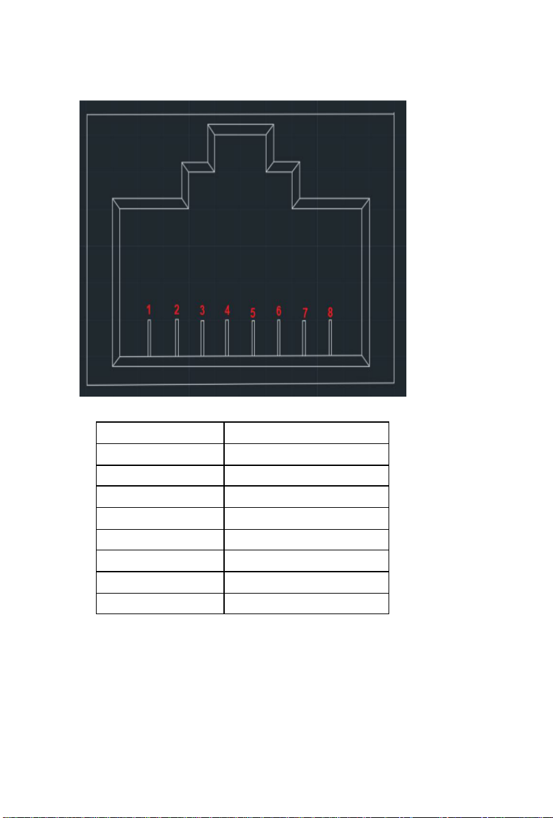
Table 2-1 The pins definition of the RS485 port
Pin
Definitions
1
RS485-B
2
RS485-A
3
GND
4
NC
5
NC
6
GND
7
RS485-A
8
RS485-B
Pic. 2 shows thecommunication wire with that of DB9 (first wire and
sixth wire are notconnected).
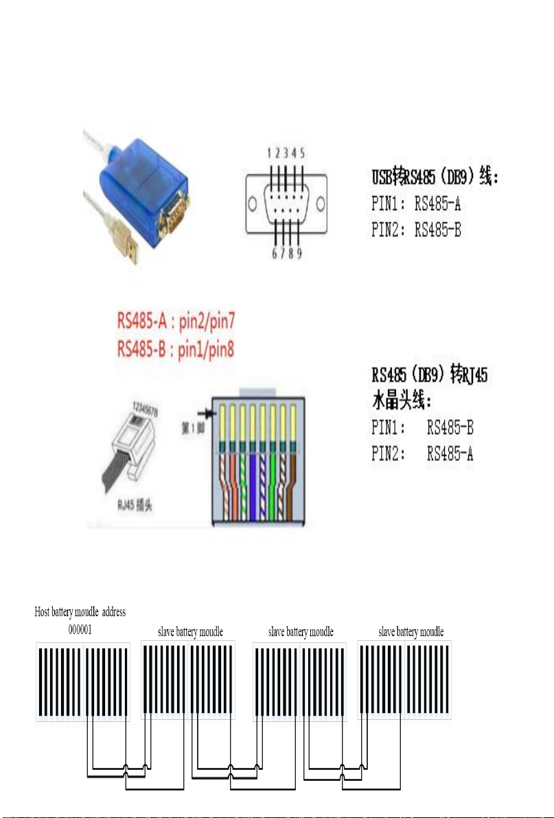
4.2.2、Communication wire
Pic. 3 shows thecascadecommunication wire connections of RS485.

4.2.3、CAN
CAN Communication Terminal:(RJ45 port)follow CAN
protocol,for output batteries information。
Table 2-2 The pins definition of the CAN port
Pin
Definitions
1
NC
2
NC
3
GND
4
CAN-L
5
CAN-H
6
GND
7
NC
8
NC
4.2.4、Power Terminals
Power cable terminals: there are two pair of terminals with same
function, one connect to equipment, the other oneparalleling to other
battery module for capacity expanding. For each single module, each
terminal can achieve charging and discharging function.

4.2.5、LED Status Indicators
4.2.5.1、LED lights order
1 RUN LED, 1 ALM LED, 4 SOC LED.
SOC
ALM
RUN
4.2.5.3、Capacity indicator
Statues
Charge
Capacity Light
L4
L3
L2
L1
SOC
0%~25%
OFF
OFF
OFF
Flash
25%~50%
OFF
OFF
Flash
Light
50%~75%
OFF
Flash
Light
Light
75%~100%
Flash
Light
Light
Light
Run Light
Long lighting
Statues
Discharge
Capacity Light
L4
L3
L2
L1
SOC
0%~25%
OFF
OFF
Light
Light
25%~50%
OFF
Light
Light
Light
50%~75%
Light
Light
Light
Light
75%~100%
Light
Light
Light
Light
Run Light
Flashing
4.2.5.4、Flashing instructions
Flashing way
Light
OFF
Flash 1
0.25s
3.75s
Flash 2
0.5s
0.5s
Flash 3
0.5s
1.5s
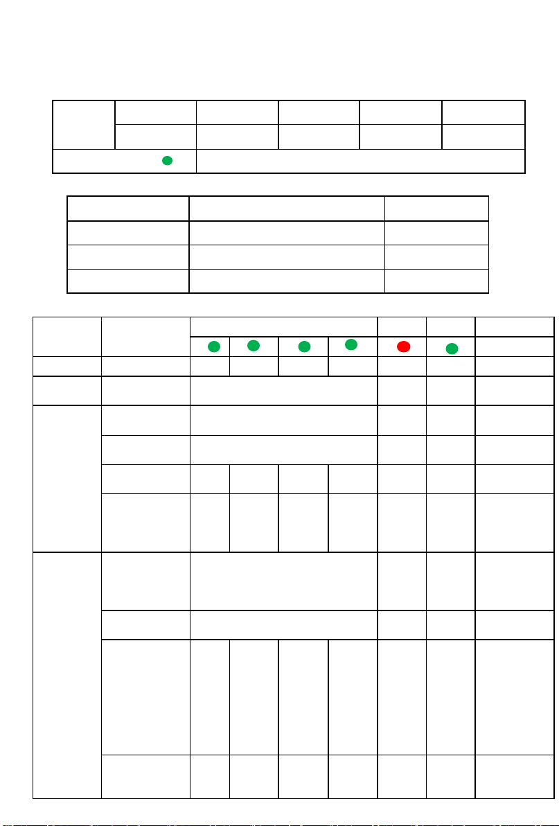
4.2.5.5、Status indication
System
status
Operation
status
SOC
ALM
RUN
Remark
Shut down
Dormancy
OFF
OFF
OFF
OFF
OFF
OFF
All OFF
Standby
Normal
Indicating according to actual
capacity
OFF
Light
Standby
Charge
Normal
Indicating according to actual
capacity
OFF
Light
The highest
LED flash 2
Over current
alarm
Indicating according to actual
capacity
Flash
2
Light
The highest
LED flash 2
Over voltage
protect
OFF
OFF
OFF
OFF
OFF
Flash
1
Temperature
and
overcurrent
protection
OFF
OFF
OFF
OFF
OFF
Flash
1
Discharge
Normal
Indicating according to actual
capacity
OFF
Flash
3
Indicating
according to
actual
capacity
Alarm
Indicating according to actual
capacity
Flash
3
Flash
3
Temperature,
over current,
short circuit
and other
protection
OFF
OFF
OFF
OFF
Light
OFF
Stop
discharging,
power
offline 48h
after no
action
forced
hibernation
Low voltage
protection
OFF
OFF
OFF
OFF
OFF
OFF
Stop
discharging,
all light off.
5. Safe handling of lithium batteries Guide
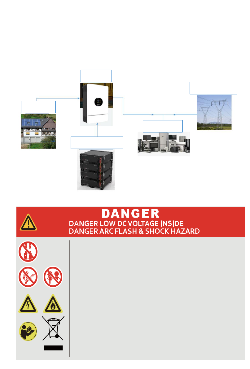
5.1、Schematic Diagram of Solution
BATTERY MODU
5.2、Explanation of Symbol
* Do not disconnectordisassemble bynon-
professional personnel.
* Do not connectthe battery packoutput positive
andnegative ports reversely.
* Do not drop, deform,impact,cut or spearingwith
a sharpobject.
* Do not placenearopen flameorflammable
material.
* Do not cover or wrap the product case.
* Do not sitor put heavy things onbattery.
* Avoid of moisture orliquid.
* Follow the product manual to make wiring
connection.
* Keep out of reachof children,animalsorinsects.
* Contact your supplierwithin 24 hours ifanything
failurehappens.
PV Arry
Inverter
Battery Module
Local Load
Public Grid

5.3、Tools
The following tools are required to install thebattery pack.
Wire cutter Crimping Modular Plier
Screw Driver styleammeter
5.4、NOTE Use properly insulated tools to prevent accidental
electric shockor short circuits.
If insulated tools are not available, cover the entire
exposed metal surfaces of the available tools, except
their tips, with electrical tape.
5.5、Safety Gear
It is recommended to wear thefollowing safety gear when dealing with
the battery pack.
Insulated gloves Safety shoes
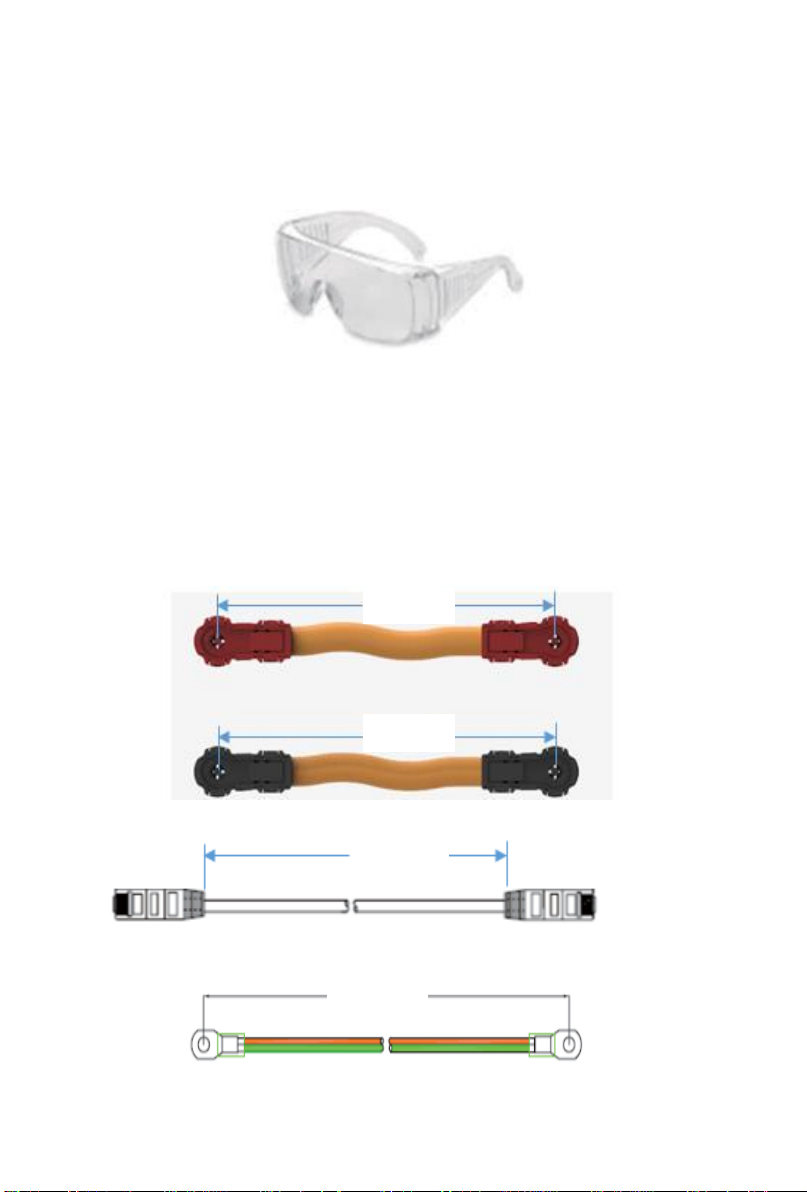
Safety goggles
5.6、Installation
5.6.1、Package Items
Unpacking andcheck the Packing List.
1)For battery module package:
Two power cables and one communication cable for each battery
package:
2)Grounding cable:
Grounding cables use10AWG yellow-green cables.
150mm
150mm
300mm
1000mm

Module grounding is based on metal directly touch between the
module’s surface and rack’s surface. So it needn’t grounding cables at all. If
uses normal rack, it can remove the paint at the corresponding place.Or
install a grounding cable to the grounding point of the modules.
3)For battery system connects to inverter:
(Need to be purchased separately,orspecify separately when placing
an order)
4000mm
Actual length
Actual length
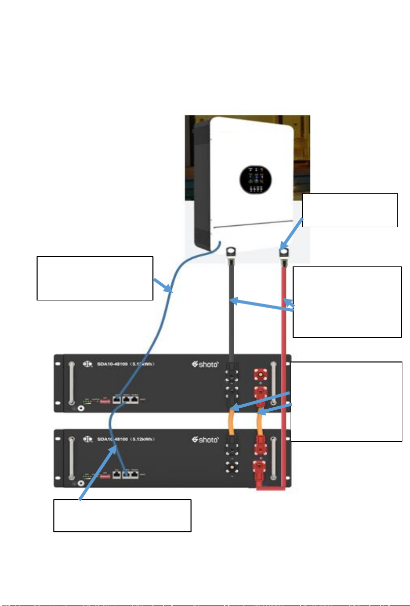
4)Two long power cables (current capacity 120A) and one
communication cable for each energy storage system.
5、Standard plug:
SC25-8 terminal
3、The length of the
wiring harness is
150mm, and the
terminals are quickly
plugged in at both
ends (maximum 120A)
4、Cable longitud:
Customize according
to actual order
(Two power cables
maximum 120A)
1、Communication line:
Inverter connected to
battery CAN。
2、Communication line:
Battery to battery RS485。

5)Adjust the ADD Switch as defined in thefigure belowe.
5.6.2、Installation Location
Make surethat theinstallation location meets thefollowing conditions:
1)The area is completely water proof. The floor is flat and level.
2)There are no flammable or explosive materials.
3)The ambient temperature is within the range from -5°C to 45°C.
The temperature and humidity is maintained at a constant level. There is
minimal dust and dirt in the area.
4)The distancefrom heat source is more than 2 meters.
5)The distancefrom air outlet of inverter is more than 0.5 meters.
Do not cover or wrap the batterycase or cabinet.
6)Do not place at a children or pet touchablearea. The installation
area shallavoid of direct sunlight.
7)There is no mandatory ventilation requirements for battery
module,but pleaseavoid of installation in confined area.The aeration shall
avoid of high salinity, humidity or temperature.
8)CAUTION:
If the ambient temperature is outside the operating range, the battery
pack stops operating to protect itself. The optimal temperature range for the
batterypack to operateis 25°C to 35°C. Frequent exposure to harsh
temperatures may deteriorate the performance and life of the batterypack.

6. Trouble Shooting Steps
6.1、Problem determination based on:
1)Whether the battery can be turned on or not;
2)If battery is turned on, check thered light is off, flashing or
lighting;
3)If the red light is off, check whether the batterycan be
charged/discharged ornot.
6.2、Preliminary determination steps:
1)Battery cannot turn on, switch on thelights are all no lighting or
flashing.
If the battery RESET switch is turned on, theRUN light is flashing,
and theexternal power supply voltage is 48V or more, thebattery still
unable to turn on, please contactdistributor.
2)The batterycan be turned on, butred light is lighting, and cannot
charge or discharge. If the red light is lighting, that means systemis
abnormal, please check values as following:
a)Temperature: Above 45℃or under -5℃, thebattery could not
work.
Solution: To move battery to the normal operating temperature range
between -5℃and 45℃.
b)Current: If current is greater than 100A, battery protection will
turn on.
Solution: Check whether current is too large or not, if it is, to change
the settings on power supply side.
c)High Voltage: If charging voltageabove 54V, battery protection
will turn on.
Solution: Check whether voltage is too high or not,if it is, to change
the settings on power supply side.
d)Low Voltage: When the battery discharges to 40.0V or less,
batteryprotection will turn on. Solution: Charge thebattery for some time,
the red light turn off.
Excluding the four points above, if the faulty is still cannot be
located, turn off power switch of the batteryand repair.
Table of contents
Other SHOTO Camera Accessories manuals


Popular Camera Accessories manuals by other brands


Trojan
Trojan GC2 48V quick start guide

Calumet
Calumet 7100 Series CK7114 operating instructions

Ropox
Ropox 4Single Series User manual and installation instructions

Cambo
Cambo Wide DS Digital Series Main operating instructions

Samsung
Samsung SHG-120 Specification sheet

Ryobi
Ryobi BPL-1820 Owner's operating manual