Showa Denki MAA1050-Y005E User manual

MAA1050-Y005E
Blower Operating
Instructions
Axial Flow/Mixed Flow Type Blower
- 1 -
Blower Operating Instructions
Introduction
Thank you for purchasing Showa Denki’s blower.
These Operating Instructions provide explanations on items for operation, maintenance, etc., of the
blower.
To ensure this blower exhibits its full performance and can be used safely without failures for a long
period of time, read these Operating Instructions carefully. Please keep these Operating Instructions at
hand for your later reference.
These Operating Instructions describe the following types of blowers.
Axial flow type blower
Mixed flow type blower
•Only the main body of the V-belt drive blower
(Motor base and belt guard are standard accessories.)
(Motor pulley and V-belt are optional.)
•M specification of the V-belt drive blower (blower in which a motor, pulley and V-belt are
incorporated)
•Only the main body of the motor shaft direct-coupling blower (impeller is an accessory)
(These Operating Instructions do not describe the assembly method because it requires
professional skills.)
•M specification of the motor shaft direct-coupling blower (blower in which a motor is
incorporated)
Symbols used in this description
The marks used in these Operating Instructions have the following meanings:
Warning This mark indicates that incorrect operation may lead to accidents
resulting in death or serious injury.
Caution This mark indicates that incorrect operation may lead to injury or
physical damage.
This mark indicates an operation that must not be performed.
This mark indicates an operation that should be performed carefully.
This mark indicates an operation that must always be performed.

- 2 -
Contents
Page
1. Safety Precautions ......................................................................................................................- 3 -
2. Overview of the Product..............................................................................................................- 6 -
2.1 Types and meanings of model symbols ..............................................................................- 6 -
2.2 Structure of the product and names of parts.......................................................................- 7 -
3. Reception of the Product.............................................................................................................- 8 -
3.1 Unloading and checking the product at the time of reception .............................................- 8 -
3.2 Movement and transportation..............................................................................................- 8 -
3.3 Storage before installation...................................................................................................- 8 -
4. Installation...................................................................................................................................- 8 -
4.1 Installation ...........................................................................................................................- 8 -
4.2 Duct connection ..................................................................................................................- 9 -
4.3 Installation of the motor (when the blower adopts the specification of V-belt drive main
body only)..........................................................................................................................- 10 -
4.4 Test operation ...................................................................................................................- 12 -
5. Operation ..................................................................................................................................- 13 -
5.1 Operation, Maintenance and Inspection............................................................................- 13 -
5.2 Replenishment of lubricating oil (grease) (V-belt drive only).............................................- 14 -
5.3 Cleaning of a blower and the impeller...............................................................................- 14 -
5.4 Management of belts.........................................................................................................- 16 -
5.5 Restart of operation after suspension or stoppage ...........................................................- 16 -
6. About the rotary sound of the bearing.......................................................................................- 17 -
7. Warranty....................................................................................................................................- 17 -
8. Malfunction Causes and Measures...........................................................................................- 18 -
- 3 -
1. Safety Precautions
Warning
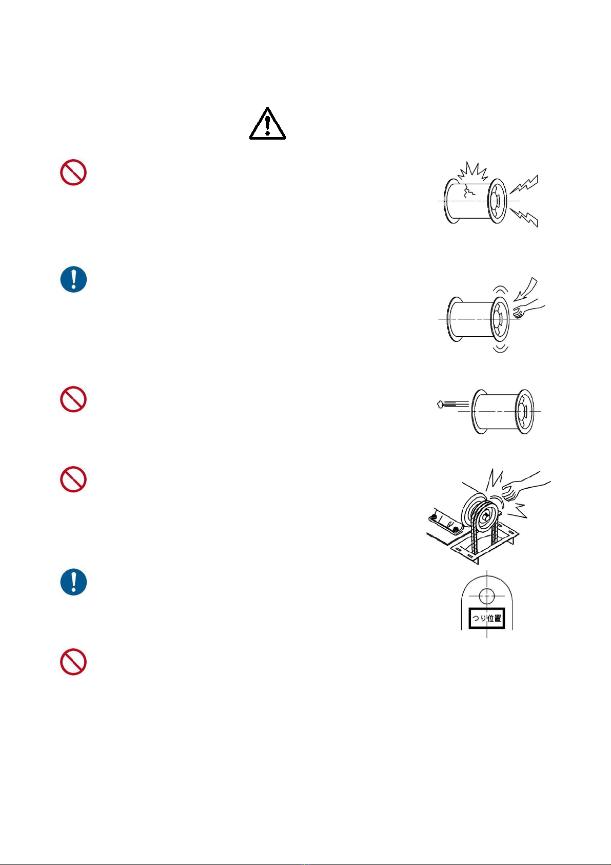
Intake of hazardous gas and installation in a hazardous
location are strictly prohibited.
This blower does not have an explosion-proof structure.
Intake of flammable gas or operating the blower in a location
with an explosive atmosphere may lead to explosion due to
a spark caused by static electricity or contact with an electric
device, metal, etc.
Attaching a metallic wire net to the intake
port/discharge port of the blower or duct.
If a duct is not attached to the intake port/discharge port of
the blower or if the tip opens even after the duct is attached,
make sure to attach a metallic wire net.
If a metallic wire net is not attached, part of the human body
or objects may be taken in or something taken in before may
rush out. This may cause a serious accident.
Keep your face away from around the discharge port.
Small dust, etc., taken in by the blower may rush out of the
discharge port at a high speed. If such dust enters the eye,
accidents such as loss of eyesight may occur. Make sure to
keep your face away from around the discharge port.
Operation with the guard removed is strictly prohibited.
Operation with the belt guard removed may cause your
hand or clothes to be caught, leading to an accident causing
injury or death.
When hoisting the blower, always use the hoisting
holes indicated as pull-up positions.
Using positions other than those specified to hoist the
blower may lead to an accident causing it to deform, turn
over, or fall.
Do not increase speed by changing a pulley or by using an inverter.
The increase of centrifugal force applied to the rotator or force applied by air flow pressure
may cause damage to the impeller or burnout due to overload of the motor.
- 4 -
Caution
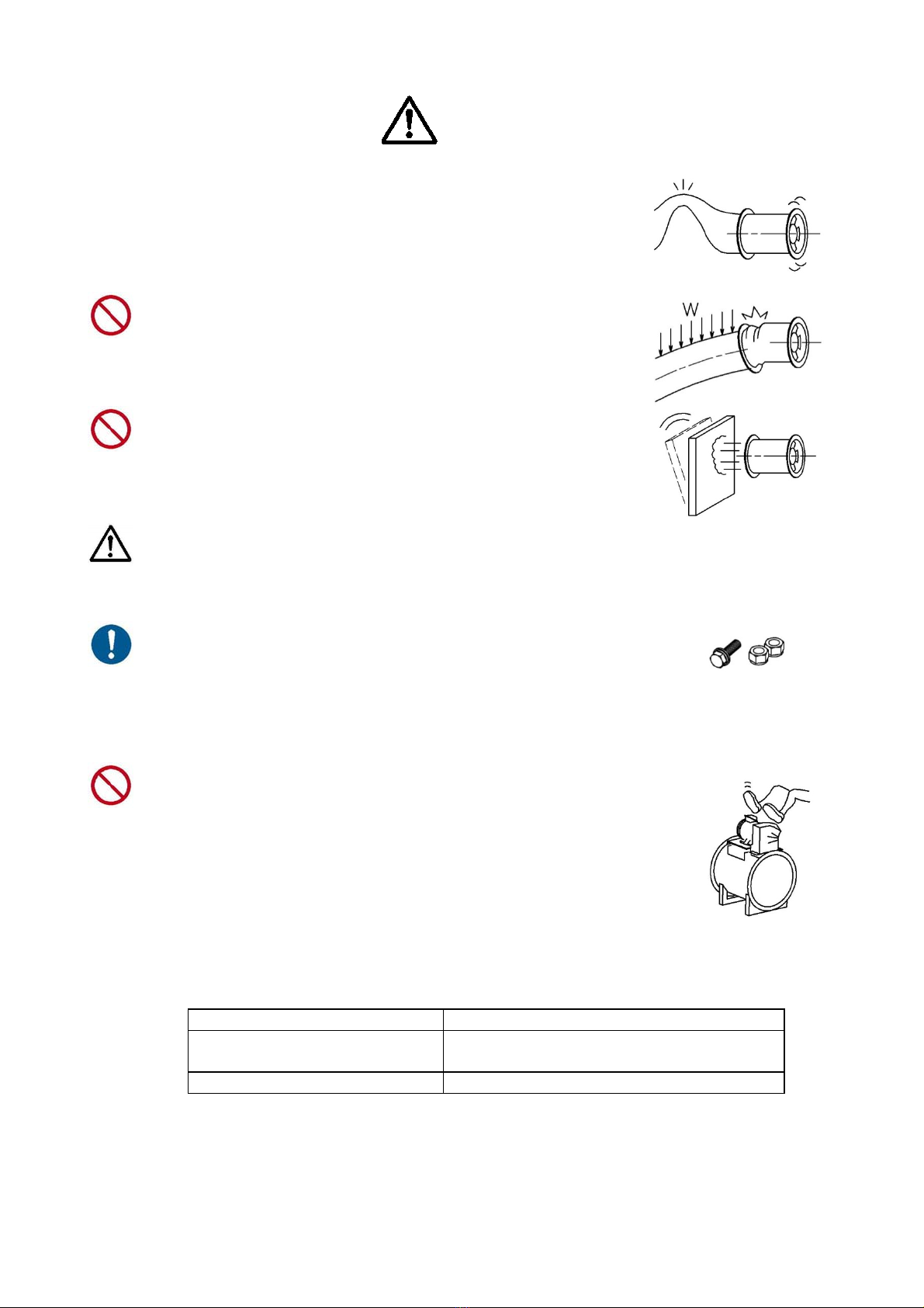
When installing piping, minimize the resistance to ducts,
pipes, etc., for air to flow smoothly. If the blower is operated
with the duct closed, it may enter stall operation status,
which may cause the impeller blade to generate abnormal
vibration, leading to an impeller damage accident.
Do not transfer the load of the duct to the blower.
Otherwise, deformation of the blower may cause contact
with the rotator, leading to an accident resulting in fire or
damage.
Remove the items that may turn over or fall due to vibration
or air flow pressure from around the blower and duct.
Otherwise, an accident may occur.
The wiring of the blower must be installed by a qualified
electrical engineer, as per the electrical equipment technical
standards and the extension rules. (Also refer to the
Operating Instructions of the motor.)
Before starting test operation, confirm that nothing is left in
the connected duct or casing or near the intake
port/discharge port, e.g., remaining materials, bolts, nuts,
tools, etc. Operating the blower with foreign material
remaining may cause an accident due to intake or rush-out,
or an accident resulting in damage.
Do not step on the blower. Otherwise, the blower may
deform or be damaged or a worker may fall.
The structure of the blower differs depending on the intake temperature. Operating the blower at a
temperature outside the range shown in the table below may cause deterioration of the belt, failure of
the bearing, and/or damage of the impeller.
Intake air temperature (°C) Blower specification
-10 or more to 50 or less Standard type (V-belt drive blower, motor
shaft direct-coupling)
50 or more to 150 or less Heat-proof type (V-belt drive blower only)
Relative humidity of 90% or less

- 5 -
The blower cannot take in solid material, dust or liquid.
Intake of them may cause an accident resulting in damage.
In the case of deceleration by an inverter, etc., a resonance between the main body and a duct
around it may cause an increase in vibration or generation of sound at a specific frequency
(rotation speed). In such a case, use the blower at a frequency other than that frequency. The
shipment inspection of this blower is performed only at the rated rotation speed*. This does
not mean that operation of the blower is guaranteed at frequencies other than that frequency.
* Operation inspection of special order products, parts, etc., may not be performed in some cases.
Precautions for the use of an inverter to operate the blower
(1) The standard motor may not be used for the operation in some cases as shown below.
•In the case that the insulation deteriorates due to surge voltage caused by the use of
a 400-V class motor whose insulation is not reinforced
•In the case of no margin for temperature rise in the motor
•In the case of no margin for allowable load GD2 of the motor
(2) At factory shipment, the setting of a commercial inverter is not suitable for the blower.
Change the following values at least.
•Base frequency: Adjust to the rated frequency of the blower (50 Hz or 60
Hz).
•Highest frequency: Adjust to the rated frequency of the blower.
•Maximum output voltage: Adjust to the rated voltage of the motor.
•Upper-limit frequency: Adjust to the rated frequency of the blower.
•Lower-limit frequency: 25 to 30 Hz (based on the cooling characteristics of the
motor).
•V/f characteristics: Change to square reduction torque.
(3) Other precautions
•The standard blower cannot be operated at an increased speed.
•Vibrations of components (belt, casing, etc.) making up the blower may increase at a
specific frequency. If the increase in vibration cannot be eliminated even after other
set values are changed, a resonance point may be causing it. In such a case, set a
jump frequency to prevent the increase in frequency.
•If the blower is installed on a vibration isolation table (rubber, spring, etc.), a
decrease in frequency may become a resonance frequency. In such a case, set the
jump frequency to prevent this symptom (otherwise, the blower and motor are
individually affected).
•If the carrier frequency is set higher, current leakage may increase, and the earth
leakage breaker may be activated.
•Do not use the inverter output power for applications other than electric motors.
- 6 -
2. Overview of the Product
2.1 Types and meanings of model symbols
Types and meanings of model symbols used for standard specifications are as shown in the
table below.
The model is indicated on the product nameplate (nameplate) affixed to the side face of the
blower main body (casing).
AV-5KM
Blank - Main body only
M - With a motor
Blank - Motor shaft direct-coupling
V - V belt drive
A - Axial flow type blower
MFT - Mixed flow type blower
Symbol of axial flow
Bore diameter
3 - Ø300
4 - Ø400
5 - Ø500
6 - Ø600
7 - Ø700
8 - Ø800
9 - Ø900
10 - Ø1000
|
|
|

- 7 -
2.2 Structure of the product and names of parts
2.2.1 Disassembling parts drawing
Note 1) The disassembling structure drawing above shows a typical example of the product
of normal temperature specification. Some product may differ from that shown in
the drawing.
Note 2) In the case of the specification of main body only, none of the motor, pulley on the
motor side and V-belt are attached to the blower.
V-belt drive
Motor shaft
direct-coupling
Normal temperature
specification
Difference in the structure based on
temperature specification
Heat-proof specification
V-belt
Pulley on the motor side
Moto
r
Motor base
Casing
A
xis
Bearing
A
xial flow impelle
r
Holde
r
Holder
Belt guard
Pulley on the fan
side
Mixed flow impeller
Mixed flow
intake cone
- 8 -
3. Reception of the Product
3.1 Unloading and checking the product at the time of reception
Although we test and inspect carefully in order to ship an accepted product, please check the
following points upon reception of the delivered product.
•Is it the exact blower that you ordered?
•Is the blower free from abnormality due to
transport, such as damage and deformation?
•Are all the set items enclosed?
•Are the bolts and nuts tightened without
looseness?
3.2 Movement and transportation
When hoisting the blower for movement or transportation, always use the hoisting holes
indicated as hoisting positions.
Avoid hoisting the blower by using only one point. It is dangerous. The hoisting operation
should be performed by a qualified person.
3.3 Storage before installation
To store the blower before it is installed, cover the overall blower with a weatherproof sheet, etc.,
even if the blower is stored indoors. (Rotate the impeller about 10 times manually once in a
month to prevent corrosion of the bearing etc. (this is also required for the blower adopting
outdoor specifications). When rotating the impeller manually, carefully prevent the hand from
being caught.
4. Installation
4.1 Installation
4.1.1 Selection of installation location
Install the blower in a location as shown below.
•A location at a normal temperature without dew condensation (at a temperature of 10 to
40 °C with a relative humidity of 90% or less)
•A location where daily inspection and maintenance can easily be performed
•An indoor location where the blower is not exposed to rainwater
•A stable location where the blower is free from vibration
•A location without hazardous chemicals
4.1.2 Base and installation
•The standard type blower should be installed horizontally. (The specification of vertical
type requires a special order product.)
•As a rough indication, the appropriate amount of concrete for the foundation is 3 times of
the mass of the blower.
•To use a mount, install the blower on the horizontal surface with a strong structure.
•If a gap is found between the blower and the foundation surface, fill the gap by inserting a
liner plate (steel plate to fill a gap), confirm that the blower does not rattle, and then tighten
the foundation bolts.
•Securely tighten the bolts and nuts.
•Remove the retaining parts used in transportation, e.g., bolts for retaining
vibration-proofing (flexible) joints, fixing fittings of the vibration-proofing base, etc.
- 9 -
4.2 Duct connection
•Install a removable duct for maintenance and inspection and an inspection hole in front of and
behind the fan.
(Secure a space for inspection with the duct removed.)
•Attach a metal wire net to each of the openings of the intake duct and discharge duct as a
safety measure.
(The metal wire net is an optional accessory.)
•If the duct is installed inappropriately, increase in resistance may cause not only a lack of air
flow but also stalled operation status, leading to accident resulting in damage to the product.
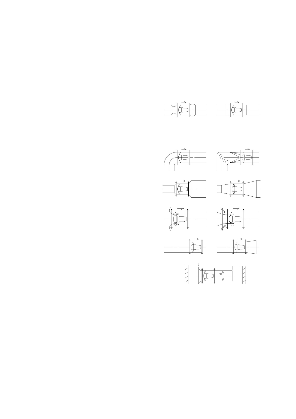
When installing the duct, pay attention to the following points:
(1) When using a flexible joint, apply
appropriate tension to it.
Keep the length to the minimum
necessary by putting in a reinforcing ring
to prevent shrinkage on the negative
pressure side in particular.
× 〇
(2) When using an elbow with a small
curvature, attach a corner vane to it.
× 〇
(3) Prevent sudden expansion and sudden
reduction.
× 〇
(4) When the intake port is open, attach an
intake bellmouth to retain the
performance.
× 〇
(5) When the discharge port is open, attach a
diffuser to retain the performance.
× 〇
(6) Prevent installing the blower with the
intake port/discharge port close to the
wall.
d or more d or more

- 10 -
4.3 Installation of the motor (when the blower adopts the specification of
V-belt drive main body only)
4.3.1 Assembly
For the names of parts, refer to the disassembling
structure drawing in page 6.
•Prepare the motor, pulley on the motor side, and
V-belt that are required.
•Exactly “center” the pulley on the fan side and pulley
on the motor side as shown in the drawing at right.
Operating the blower with them not centered exactly
causes abnormal vibration of bearing and/or
significant reduction in the durability of V-belt, pulley
and bearing.
•Adjust the tension of the belt as follows: Neglecting
the tension adjustment causes a failure.
When adjusting the tension of the belt, use
adjustment nuts to fix the motor base.
•Procedure for tensing the belt
Step 1. Span calculation
First calculate the span (ℓ) of the V belt.
The span of the V belt is part of the connection
of the V belt with the motor pulley and the fan
pulley.
Step 2. Calculation of deflection
When a deflection load is applied, calculate the
deflection (δ) by the formula at right.
Step 3. Measurement of deflection load
Apply a deflection load (P) to the center of the
belt span. When the deflection of δmm is the
value calculated in Step 2, read the value of the
deflection load.
It is convenient to use a tension meter etc., for
measurement of deflection load.
X
Pulley on the
fan side
V belt
X≒0
A
djustment nuts
Pulley on the
motor side
ℓ
δD
d
P
C
(D-d)2
=C2 -
4
ℓ:span (mm)
C:distance from shaft (mm)
D:big pulley diameter (mm)
d:small pulley diameter (mm)
ℓ
Span
δ = 0.016 ×ℓ
δ: Deflection (mm)
ℓ: Span (mm)
Deflection

- 11 -
Step 4. Tension adjustment
Adjust the tension of the belt in such a manner that the read value of the deflection load
matches that shown in the following table.
Table of deflection load
Types of
belts
Range of small
pulley diameter
(mm)
Deflection load P (N/belt)
Minimum value When a new belt
is stretched
When a belt is
stretched again
M type 38 to 50 4.9 6.9 6.9
A type
65 to 80
81 to 90
91 to 105
106 or more
7.8
8.8
10.8
11.8
11.8
13.7
16.7
17.6
9.8
11.8
13.7
15.7
B type
115 to 135
136 to 160
161 or more
13.7
17.6
18.6
20.6
26.5
28.4
17.6
22.5
24.5
3V type
67 to 90
91 to 115
116 to 150
151 to 300
17.6
19.6
22.5
25.5
24.5
28.4
33.3
38.2
21.6
25.5
29.4
33.3
5V type
180 to 230
231 to 310
311 to 400
57.8
69.6
82.3
85.3
103.9
121.5
74.5
90.2
105.8
(Note) The range of small diameter of 3V/5V type is indicated in nominal diameter.
•A lack or excess of belt tension causes abnormal phenomena. The following table
indicates how to distinguish a lack of belt tension and an excess of belt tension from each
other.
Abnormal phenomena of belt
Phenomena caused by a lack of tension Phenomena caused by an excess of tension
•Slip
•Heat generation
•Overturn
•Vibration
•Aging of rubber resulting in cracks
•Wear of side face
•Reduction of lifetime due to deformation of
the belt on the pulley
•Heat generation
•Heat generation of bearing
•When a belt gets used to the pulley 20 to 30 hours after it enters the field operation phase,
perform a fine adjustment of the belt once again.
•When using multiple belts stretched, make them matched set for the number of belts to be
used (make the belts the same length).
•When the tension of the belts has completely been adjusted, make sure to attach the belt
guard to ensure the safety.
Correct Deformation

- 12 -
4.3.2 Electric wiring
•The electric wiring of the blower must be installed by a qualified electrical engineer, as per
the “electrical equipment technical standards” and the “extension rules.”
•Confirm the power supply specified on the product nameplate affixed to the side surface of
the main body and then use the power supply for this blower. Using a power supply other
than that specified on the nameplate to operate this blower is dangerous and may cause a
failure.
•Select an earth leakage breaker or breaker of the power supply appropriate for the current
at the time of startup.
•Ground the blower to prevent electric shocks.
•Also read the Operating Instructions of the electric motor.
•Install electric wiring to rotate the blower in the correct direction. (For details, see Section
4.4.)
4.4 Test operation
Before starting up the blower for test operation, make sure to perform the following inspection
to confirm that the condition is normal.
•Confirm that materials, bolts, nuts, tools, etc., used in construction works are not left inside
the duct or casing, or near the intake port/discharge port.
•Confirm that the blower installed is free from rattling and that all the bolts and nuts are
tightened without omission.
•Confirm that the protective parts used in transport have been removed.
•Confirm that a metallic wire net has been attached with the intake port/discharge port open.
•Check the electric wiring.
•Confirm that the items above are normal, turn on the switch once, and then turn it off
(inching) immediately to check for abnormal vibration or contact sound. At the same time,
visually confirm the rotation direction. (Affix a seal to the main body to indicate the rotation
direction.) If the blower rotates in the reverse direction, it makes the air flow in the reverse
direction.
•If the rotation direction is reversed, turn off the source power supply, switch two of the three
power cables with each other while the other cable remains connected, and then confirm
the rotation direction. Since different motor rotation directions and motor installation
directions are available for the blower, the wiring method may differ from the indication on
the motor terminal box. Also, since the colors of cables and phase of the power supply may
differ depending on the power company, reverse rotation may occur even if cables of the
same color are connected. When the power is initially supplied, make sure to confirm the
rotation direction.
•If no abnormality is found during inching, rotate the blower continuously to check for
abnormal noise. In addition, measure and record vibration values and current values, and
confirm that they are in the normal ranges.
•Before starting the formal operation, replenish the blower with the specified grease that
came with the blower. (See Section 5.2.)
•When using an air flow adjustment damper, open it fully at first, and then gradually throttle it
to reduce the degree of opening. If a change is detected in the course of throttling the
damper, e.g., sudden noise, increase in vibration, decrease in pressure, etc., degree of
opening to the fully closed side is not allowed so as to prevent stalling. When an axial flow
type blower is used, the range of air flow adjustment by a damper is limited and a judgment
must be made taking into account the above-mentioned consideration. It is recommended
to change the rotation speed for air flow adjustment.

- 13 -
5. Operation
5.1 Operation, Maintenance and Inspection
After starting to operate the blower, perform the maintenance and inspection regularly. If daily
inspection is performed on the following items from the beginning of the operation and the results
are recorded, abnormalities can be detected early to prevent problems. During the maintenance
and inspection, an experienced worker or trained worker should secure the safety. Inspect the
motor based on the operating instructions of the motor.
Inspection item
Recommended inspection cycle
Inspection contents
3 months 6 months 12 months
Condition inspection
Abnormal
noise
Blower
■
□
□
Check for abnormal noise due to rattles.
Check for metal contact noise.
Check for other noise considered to be
abnormal.
Motor
■ □ □
Check the grease.
Check for loose bolts.
Check the bearings for abnormal noise.
Vibration
■ □ □ Check the vibration value and any
changes to it.
Temperature
■ □ □ Check the temperature near the bearing
and any changes to it.
Electrical
section
□ ■ □ Check the current value and voltage
value, and any changes to them.
Component
inspection
V-belt
■ □ □ Check the tension.
Check for wear or cracks.
Pulley □ □ ■ Check for wear or cracks.
Coupling
Rubber bushing
□ ■ □ Check for hardening.
Check for wear or cracks.
Anti-vibration
rubber
□ ■ □ Check for hardening.
Check for wear or cracks.
Shaft seal □ □ ■ Check for cracks or damage.
Packing □ □ ■ Check for damage or hardening.
5.1.1 Abnormal noise
If an abnormal noise is heard, immediately stop the operation to perform inspection.
Possible types and causes of abnormal noise are as follows:
•Bearing sound
Abnormal lubricating oil (shortage/deterioration of lubricating oil, mixture of foreign materials,
deterioration due to injection of different type of oil)
Abnormality and lifetime of bearing
•Contact sound
Deformation/damage of Impeller/casing
Intake of foreign materials
Rattling due to looseness of bolts
•Chattering noise
See “Vibration” in the following section.
Pulsing sound (unstable fluid sound)
Excessively throttled air flow
Excessively large resistance of the device
- 14 -
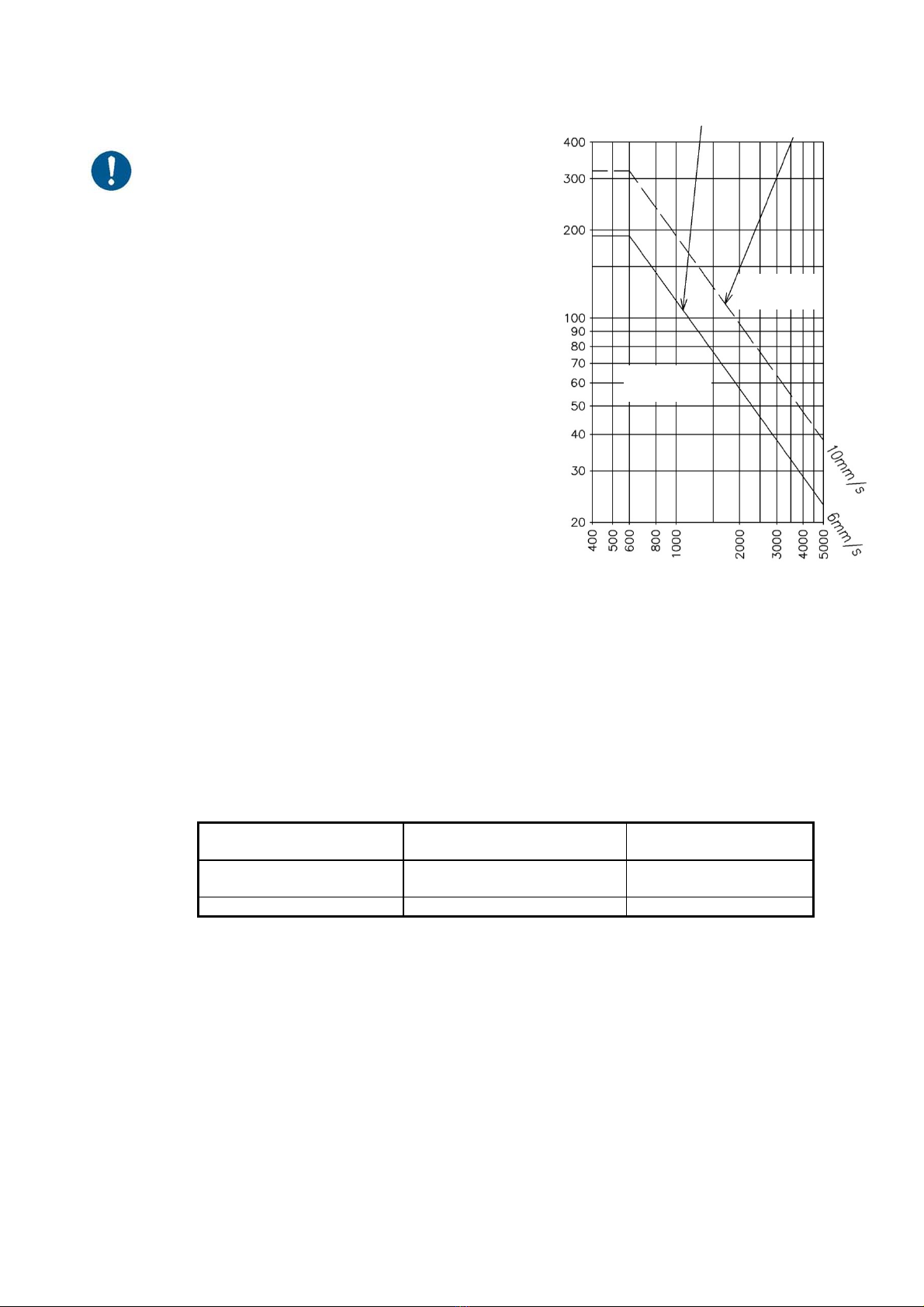
5.1.2 Vibration
If vibration exceeds the allowable value, stop
the operation and perform the inspection.
Possible causes of vibration are as follows:
•Unbalance of the impeller due to adhesion of dust to it
•Deformation/damage of Impeller/casing
•Abnormal axis or bearing
•Rattling due to looseness of bolts
•Stall operation or variation of flow
•Transmission/resonance of vibration
•generated from the duct/mount
•Lack of rigidity of duct or mount
5.2 Replenishment of lubricating oil (grease) (V-belt drive only)
Regularly replenish the bearing with lubricating oil (grease) is also necessary to use the blower
safely for a long period of time. Even if high quality grease is used, its lubricating function reduces
due to deterioration or hardening of the grease itself as the period of use lapses. Therefore,
replenish the blower with the appropriate amount of new grease at the appropriate time.
•When replenishing, select the grease from the following table.
Table of brands of specified grease
Temperature specification
of blower Grease manufacturer Product name of grease
(brand)
Normal temperature
specification Showa Shell Sekiyu K.K. Albania S3
Heat-proof specification Dow Corning Toray Co., Ltd. SH44M
(Remarks) A label indicating the “type of grease and interval for replenishment” is
affixed to the product.
The brands above are standard grease for the standard type of bearing
“pillow block bearing” used in this product.
For special specification products, refer to the separate reference materials.
•If a foreign material mixes with grease, it causes damage to the bearing. Store grease in a
closed container. Prevent grease of a type from mixing with that of a different type.
•Prevent decreasing the number of replenishments by increasing the amount of grease for a
replenishment.
•Be sure to confirm safety, and then replenish the bearing with grease during operation.
•For interval for replenishment and the replenishment amount, use the table below as a rough
indication.
Acceptable
Unacceptable
Vibration allowance value
Vibration allowance value
with antivibration
equipment
Tot
al
am
plit
ude
(
μ
m)
Rotation speed (min
-
1
)
Vibration allowance value graphic
- 15 -
Rough indication of interval for replenishment of grease
Temperature of
handled gas
ºC
Environmental conditions
Quite clean
(normal
environment)
Much refuse (flour
mill, sawmill, dust
collector, etc.)
Large volume of dust, high
humidity, or much spray or
water (refuse disposal
facility, processed marine
product factory, etc.)
50 or less 6 months 3 months 1 month
50 to 80 3 months 2 months 1 month
80 to 150 2 months 1 month 1 week
*1 The bearing must not be directly affected by water or refuse.
*2 If the temperature exceeds 80°C, reduce the interval for replenishment by 1/1.5 each
time the temperature increases by 10°C.
Rough indication of the replenishment amount of grease
Bearing
type
Repleni
shment
amount
(g)
Bearing
type
Repleni
shment
amount
(g)
Bearing
type
Repleni
shment
amount
(g)
Bearing
type
Replenis
hment
amount
(g)
Bearing
type
Replenis
hment
amount
(g)
UC203
204
205
206
207
1.2
1.2
1.3
2.3
3.5
UC208
209
210
211
212
4.3
4.9
5.6
8.0
9.8
UC213
214
215
216
12
15
16
19
UC307
308
309
310
311
5.4
6.7
8.4
12
17
UC312
313
314
315
316
20
27
32
38
45
(If a grease gun, which is our standard tool that comes with the product, is used, the
replenishment amount is approx. 0.5 g each time the lever is operated.)
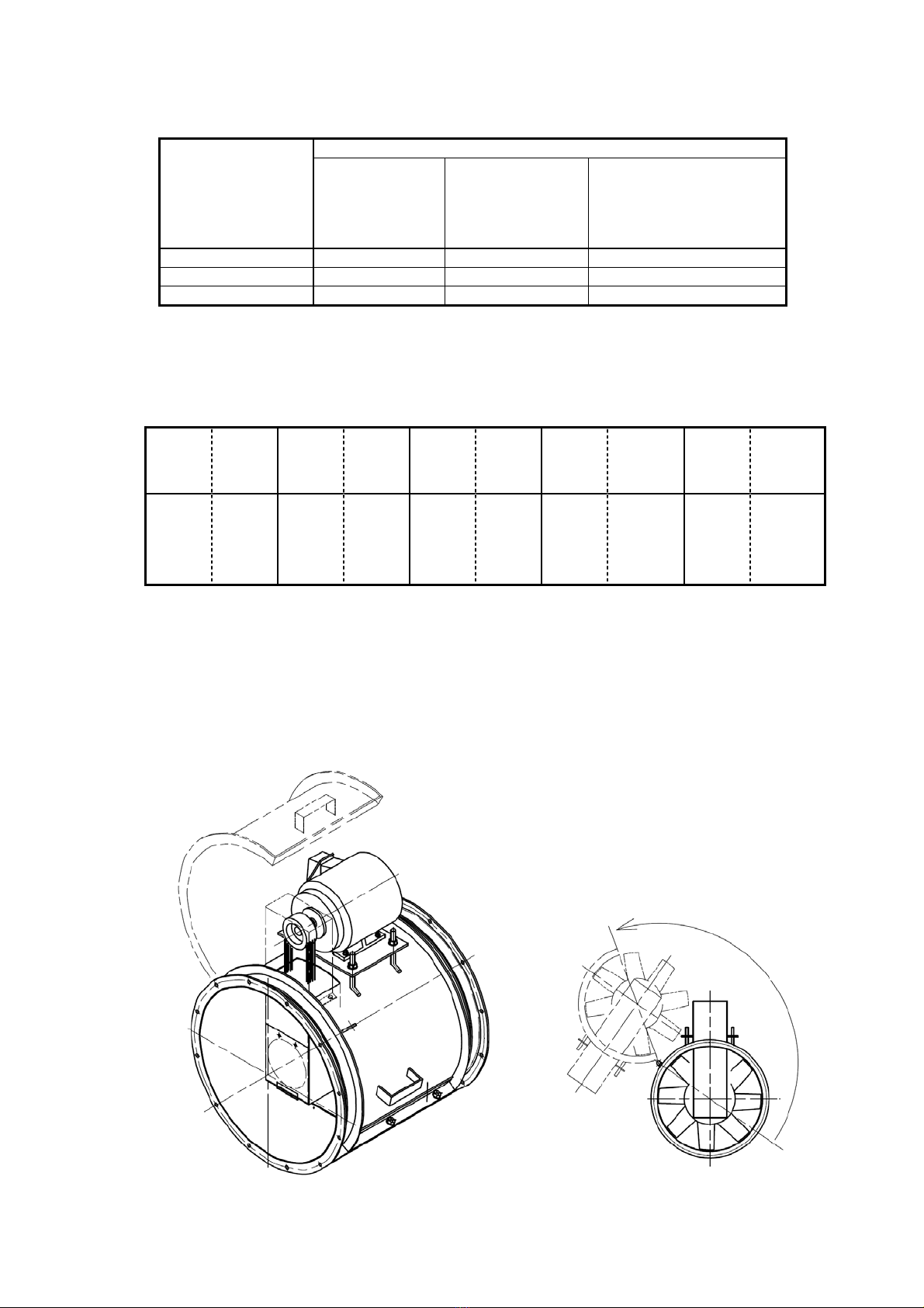
5.3 Cleaning of a blower and the impeller
When an ACT type blower is used in a way similar to painting booth and this, please check
cleaning regularly by all means because an alien substance attaches to a blower part and an
impeller. In addition, the ACT type blower becomes the structure that internal check is easy to
make like a figure.
Open

- 16 -
5.4 Management of belts
For the belt, perform the tension management and visual inspection regularly according to the
description in section 4.3.1. If the blower has a belt driving system, powder dust is generated
from the belt. In particular, the amount of powder dust may be a little larger for approx. 2 months
after the start of operation. Unusually much powder dust may be generated due to abnormal
wear of the belt caused by inappropriate tension or inaccurate centering. In such a case, perform
an inspection.
5.5 Restart of operation after suspension or stoppage
In the case of suspension of the operation, take care about the storage environment even if the
period of storage is short. To prevent rust of the bearing, etc. during the suspension period,
rotate the impeller approx. 10 times manually or perform no-load running for approx. 5 minutes
once in a month. Before the restart of operation, make sure to perform an inspection similar to
that for test operation. In particular, check for materials adhering to the impeller or for corrosion
on it.
6. About the rotary sound of the bearing
The blower of the high-speed rotary or high temperature specifications of this blower chooses the
bearing of the C3 skimmer.
Therefore "a ball omission sound" may occur at the time of driving, but is not the abnormality of
the bearing.
When a rolling body enters the no load zone at the load zone, I come to be able to carry out a free
activity and begin to roll by gravity, and "a ball omission sound" is a sound when it collides in a
retainer and the orbit.
I show the example of the typical driving sound of the bearing.
Expression of the
sound Characteristic
With ticktacks
Clangor
It attract attention in low speed.
It is consecutive sounds at a high-speed turn
Metallic sound
It change by a change of the rotary speed with a cylinder
Roller bearing and sound like a metallic sound mainly
when
it is big.
It stay temporarily when I supply grease.

- 17 -
7. Warranty
Scope of warranty
Repair service is provided free of charge for a failure during the warranty period, as long as the
blower has been used in compliance with these Operating Instructions, labels attached to the
body, and other instructions.
In the case that this product is incorporated into other equipment used by the customer, the
warranty does not cover costs for removal from such equipment, reattachment to such
equipment, costs of other incidental work, costs of transportation etc., resulting opportunity loss
incurred by the customer, lost operation, or any other indirect loss or damage suffered by the
customer.
•For requests for repair service, please contact our nearest branch or sales office.
Warranty period
One (1) year from the date of delivery of the product.
Even during the warranty period, only charged service is provided in principle, if any of the
following applies:
•Failure or damage due to incorrect use that is not compliant with these Operating Instructions,
labels attached to the body, or other instructions, and/or unauthorized repair or modification
•Failure or damage due to transportation, dropping, etc. after the purchase
•Failure or damage due to fire, earthquake, storm, flood, lightening or other natural disasters,
environmental factors such as salt damage and public pollution, abnormal voltage, use of a
power supply (voltage or frequency) other than that specified, or the like
•Failure or damage due to repair or modification (including punching, etc. in the product) not
conducted by our company
•Failure or damage due to the use of parts other than those designated by our company
•Failure or damage due to the entry of foreign material
•Discoloration, scratching, natural consumption of consumable parts or other defects due to
use or deterioration over time
•Failure or damage caused by neglecting the maintenance and inspection described in the
Operating Instructions
We will not compensate for any loss or damage resulting from defects that occur during the
use of this product.
[Notices]
(1) The descriptions in these Operating Instructions are subject to change without prior
notification in the future.
(2) We have made all possible efforts to prepare these Operating Instructions. However, if you
have any questions about them or find any inquiries, errors, omissions, etc., please contact
our nearest branch or sales office.
(3) If the power supply frequency changes due to a change in the location where the blower is
used, it may not be used as it is. We will consider a measure in each case where it is
required. In such a case, please contact our nearest branch or sales office.
(4) At the time of inquiry, please describe the product type and the manufacturing number
indicated on the product nameplate.
- 18 -
8. Malfunction Causes and Measures
Fan malfunction causes and measures
Malfunction status
Malfunction cause
Overs and shorts of quantity
of wind, the static pressure
Excess/short of motor
Bearing overheat/burnout
Abnormal vibration
Peculiar noise
Corrosion and wear
Abnormal contact
Motor not activated
Measures
Defective installation
○○○○○Re-installation
Poor foundation ○○○Renovation
Contact with the rotator? ○○○○○○Processing of contact part,
and re-installation
Defective duct/duct joint ○○○○○○Renovation
Defective lubricating oil ○Replenishment
Inappropriate oil quality,
contamination, excessive
amount of oil
○Replacement or recycling
Inappropriate material ○○○Replacement
Unbalanced impeller ○○○○Correction
Deformation or damage of
impeller ○Repair or replacement
Wear or corrosion of impeller ○○
Repair or replacement
Operation at a dangerous speed ○○○○
Renovation or remodeling
of operation point
Abnormal bearing of the motor ○○○Replacement
Wrong rotation direction ○○○○○Change
Malfunction of the motor ○○○○○Repair or replacement
Intake of light gas ○
Renovation/replacement of
impeller
Intake of heavy gas ○○
Renovation/replacement of
impeller
Mixture of foreign object or
adhesion of scale ○○○○○○○Cleaning
Surging operation ○○○Change of operation point
Resistance to the pipe system ○○Renovation
Failure of damper ○○○○○Repair
Accumulation in the drain ○○○○○Draining
There is less pressure loss than
a plan ○○
Damper adjustment,
change of the rotary speed

Note on your purchased blower
Fan identification information that you may need when making an inquiry of us.
TYPE SERIAL NO.
Date of
Purchase Year/Month/Day Date of start
of operation Year/Month/Day
Supplier
TEL: Person in charge:
Table of contents
Other Showa Denki Blower manuals


