Showco Spot 575 User manual


1.Openthe box and check ing
C ongratulations on choosing our products! Please carefully read this instruction m anual in its
entirety and keep itwellfor using reference. This m anual contained about the installation and the
relative using information ofthis products. Please accordi
ng to this m anual's relative speaking when
using this equipm ent.
This equipm ent w as m ade of new style, high intensity plastic and cast alum inium . Itfully
show s the m odem timeslightcharacteristic with beauty structure.A nd itwasmadeaccording to CE
standard. Fully up the international standard of D M X 512 agreem ent.Master or slave in phase
control.Canbe use in large entertainm ent,theater,performing and playing hall,etc.
This productuses MSR575/2 electrical arc lam p.Whenreceiving this productplease carefully
bring and put;and check thatwhetherthis equipm enthas been dam aged ornotduring transportation.
A nd please also check the follow ing thing wasenclosed:
Signal line -----------------------one piece Safety string -----------------------one piece
UserManual-----------------------one set
2.S a fe ty instructions
Every person involved with installation and maintenance ofthis device have to:
- be qualilfied
- fo llow the instru c tionsof thism anual
CAUTION:
ØK eep thisdevice aw ay fro m rain and moisture!
ØU nplug mainslead b efo re opening the housing!
ØFOR YOUR OW N SA FETY,PLEA SE READ TH IS USER M ANUALCAREFULLY
ØBEFOREYOU IN IT IA L STA RT -UP!
ØBecarefulwith youroperations.
ØWith a high voltage you can su ffe r a dangerous electric shock whentouching the
wires!
ØThis device has leftour prem ises in absolutely perfect condition.In orderto maintain
this condition and to ensure a safe operation,itisabsolutely necessary fo r the user to
fo llow the safety instru c tionsand warning notes writtenin this m anual.
Im p ortan t:
ØThe m anufacturerwillnotaccept liability fo r any re su lting dam agescaused by the non-
observance ofthis m anualor any unauthorized m odification to the device.
ØPlease considerthatdam agescaused by m anualm odificationsto the device are not
subject to w a rra n ty.
ØNeverletthe pow er-cord com e into contact with other cables!H andle the pow er-cord
and allconnections with the mainswith particularcaution!
ØMakesu re thatthe available voltage is nothigher than stated on the rearpanel.
ØAlwaysplug in the pow er plug least.Makesu re thatthe pow er-sw itch is set
to O FF-
position b efo re you connectthe device to the mains.Thepow er-plug hasto be
accessable afterinstalling the device.
ØMakesu re thatthe pow er-cord isnever crimpedor dam aged by sh arp edges.C heck the
device and the pow ercord fro m timeto time.
1
www.carlosmendoza.com.mx

Øby the plug.Neverpulloutthe plug by tugging the pow er-cord.
ØThis device fa lls underprotection classI. T herefore itisessen tialto connectthe
yellow /green conductorto earth.
ØThe electric connection,rep airs and servicing mustbe c arried outby a qualified
em ployee.
ØDonotconnect thisdevice to a dimmerpack.
ØDonotsw itch the fixture on and offin shortintervals as this w ould reduce the lam p s
life .
ØDuring the initial start-u p so m e sm oke or sm ellmayarise.This isa norm alprocess and
does notnecessarily mean thatthe device isdefective.
ØDonottouch the device shousing bare hands during its operation (housing becom es hot)!
ØForrep lacem entuse lam ps and fu se s of sam e type and ra ting only.
CAUTION :
EYE DAM AGES!
A void looking directly into th e light source(m ean tesp ecially fo r ep ilep tics) !
Ø
Ø
Ø
Ø
Ø
Ø
Ø
Ø
Ø
Ø
Ø
3.O p erating d eterm inations
This device isa m oving-head spotfo r creating decorative effects and wasdesigned fo r
indoor use only.
If the device hasbeen exposed to drastic tem perature fluctuation (e .g.Aftertransport-
ation),do notsw itch iton immediately.Thearising condensation water mightdam age
your device.L eave the device sw itched offuntilithas reached room tem perature.
Neverru n the device withoutlam p!
Donotshake the device.Avoid brute fo rc e wheninstalling oroperating the device.
Neverlift the fixture by holding itatthe projecto r-h e ad ,as the m echanics maybe
dam aged.A lwayshold thefixtur
e atthe transporthandles.
Whenchoosing the installation-spot,please makesure thatthe device is notexposed to
extrem e heat,moistureor dust.T here should notbeany cables lying around.You
endanger yourow n and the safety of others!
The minimum distance betw een light-outputand the illum inated surface mustbe more
than 2 meters.
Makesu re thatthe area below the installation place isblocked whenrigging,derigging
or serv icing the fixture.Alwaysfix the fixture with an appropriate safety-rope.Fix the
safety-rope atthe correctholes only.
Only operate the fixture after having checked thatthe housing is firm ly closed and all
screw s are tightly fastened.
The lam p mustneverbe ignited if the objective-lens orany housing-coveris open,as
discharg e lam ps m ayexplose and em ita high ultrav ioletra d iation,which maycause
burns.
The maximum am bient tem perature ta = 40 mus
tneverbe exceeded.Otherw ise, the
lam p issw itched offandthe fixture is outof operation fo r 5 minutes..
2
www.carlosmendoza.com.mx
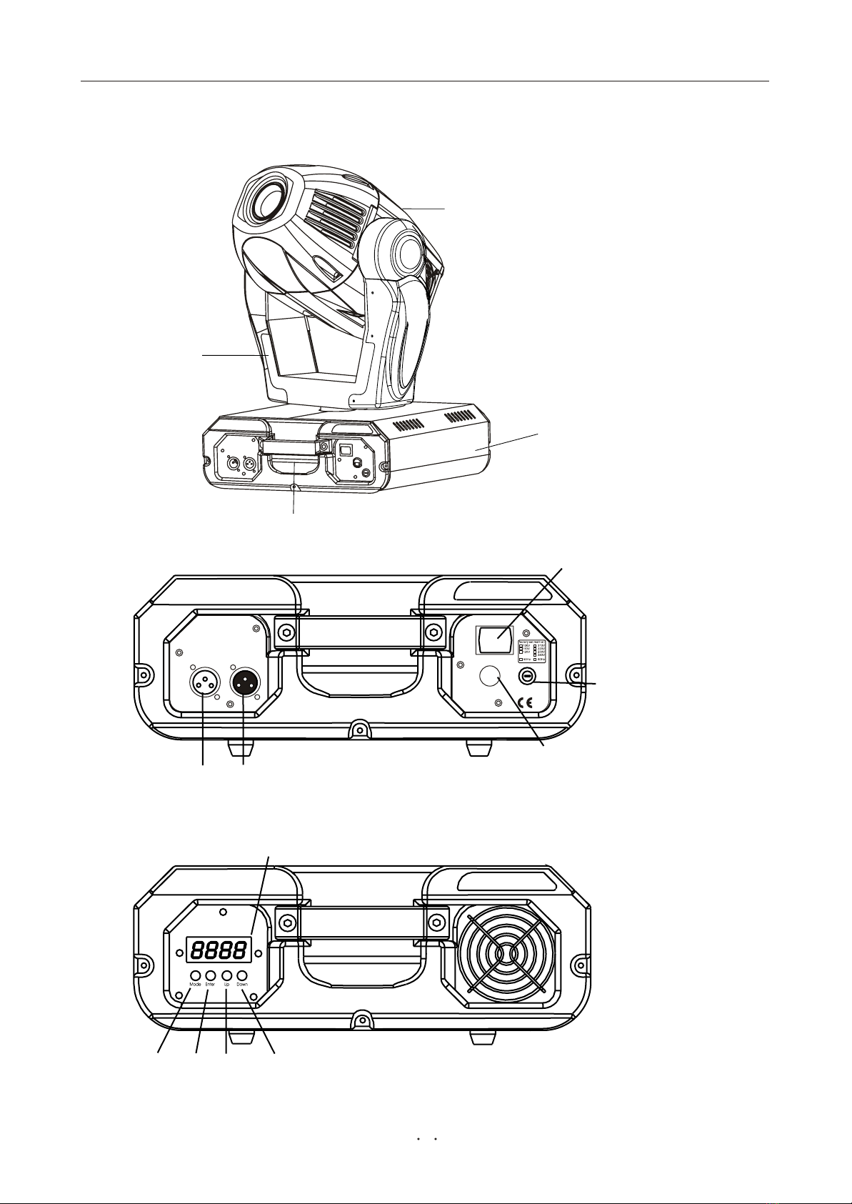
4.D escription ofth e device
Frontpanel:
10 -
M ode-button
11 -Enter-button
12 -Up-button
13-Down-button
14
-Display
R earpanel:
5 -Powersw itch
6 -DMX output
7-DMX input
8-Powercord
9-Fuse holder
1 -Mov
ing head
2-Yo ke
3-Carry handles
4 -Bas
e
3
1
2
3
4
POW ER
LAM P:
MSR575/2
LAM P:
MSR575/2
POW ER SUPPLY
POW ER SUPPLY
FUSE 10A
FUSE 10A
1=G N D
2=S IG.-
3=S IG.+
OUT DMX IN
OUT DMX IN
SERIALDATA LINK
LIGHTING CONTROL PROTOCOL:DM X512
Serialnum ber:
5
67
8
9
10 11 12 13
14
www.carlosmendoza.com.mx
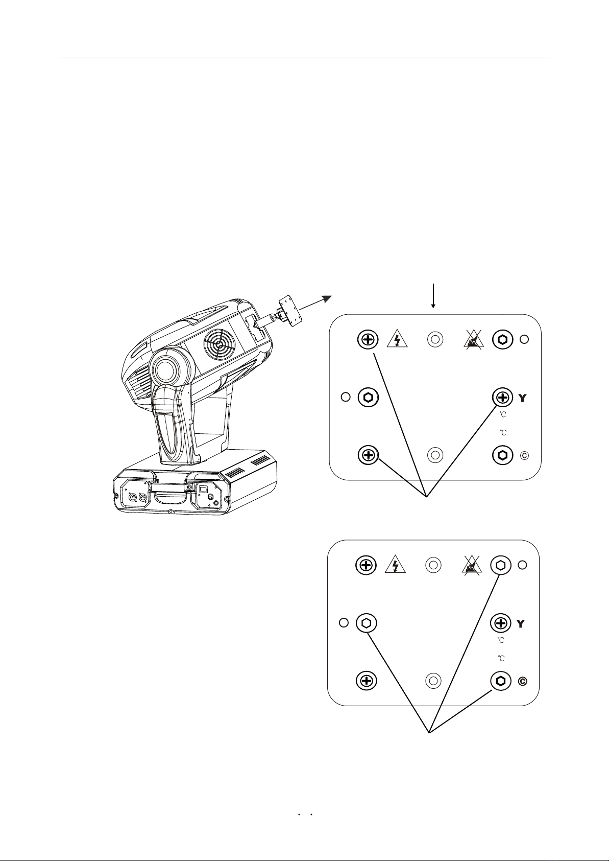
5.In stallion
To insertthe lam p MSR575/2 95V /575W GX-9,5 loosen the lam p cover atthe rearof
head (see the draw ings) by rem ow ing the 3 fastening screw s which are marked"X ,Y,Z".
C a refu lly pulloutthe coverwith the lam p socketassem b ly.If changing the lam p,rem ove
the old lam p fro m the socket.In sert the lam p to the socket.
Donotinstalla lam p with a higherwattage! A lam p like this generates tem peratures the
device isnotde-signed fo r.Damagescaused by non-observanceare notsubject to w arran ty.
Please follow the lam p m anufacturer notes!D o nottouch the glass-bulb with bare hands
during the installation! Makesu re thatthelam p isinstalled tightly into the lam pholder
system .
R eclose the lam p coverand tighten the 3 screw s.
.Lam p assem b ly:
5.1Fitting th e lam p
3 phillips screw s "X ,Y,Z"
Lam p cover
Donotoperate this fixture with opened housing-cover!
3 adjustm entscrew s "A ,B,C"
5.2 Lam padjust
TheSPOT 575 lam pholderisaligned at
the factory. Dueto diffe ren ce s betw een
lam ps ,fine adjustmentmayim prove light
p erfo rm an c e.Strike thelam p,open theshutter
and theiris,set thedimmerintensity onto
100% and fo cu s thelighton a flatsurface
(w all).Center a hot-spot(the brightestpartof
the image)by using the 3 adjustmentscrew s
"A ,B,C".Turn one screw after anothera
quarte r-turn clokw ise(counte r-clokw ise. If
you cannotdetectthehot-spot,adjustthe
lam p untilthe lightis evenly distributed.
Rem ovethe screw s X,Y and Z forre -lam ping
WARNING!
Disconnectthe fixture fro m A C pow erbefore re -lam ping.
Lam p is hot!Risk offire ! Protecthands and eyes.
Waitatleast15m in.Before opening the covers
and re m o v ing lam p fro m the fixture.
Maximum room tem perature t=40
Minimum distance fro m flammablemateriald=0.5m .
Exteriorsurface tem perature T=80 .
Notfordom esticuse.
X
Z
A
B
Adjustlam p position by turning screw s A ,B and C
Rem ovethe screw s X,Y and Z forre -lam ping
W ARNING!
Disconnectthe fixture fro m A C pow erbefore re -lam ping.
Lam p is hot!Risk offire ! Protecthands and eyes.
Waitatleast15m in.Before opening the covers
and re m o v ing lam p fro m the fixture.
Maximum room tem perature t=40
Minimum distance fro m flam m ablemateriald=0.5m .
Exteriorsurface tem perature T=80 .
Notfordom esticuse.
X
Z
A
B
Adjustlam p position by turning screwsA,B and C
4
www.carlosmendoza.com.mx

5.4 Riggingth e fixture
DANGER TO LIFE:Please consid er th e resp ective nationalnorm sduringth e
installation!T he installation mustonly be carried outbyan authorized dealer!
ØTheinstallation oftheprojectorhasto bebuiltand constru cted in a waythatitcan hold 10
timestheweightfo r 1 hourwithoutany harm ing d e fo rm ation.
ØTheinstallation mu
stalwaysbe secured with a secondary safety attachm ent,e.g.an
appropriate catch net.Thissecondary safety attachm entmustbe constru cted in a waythat
no partoftheinstallation can falldow n if themain attachm entfails.
ØWhenrigging,derigging orserv icing the
fixture staying in thearea below the installation
place,on bridges,underhigh working places and otherendangered areas isfo rb idden.
ØTheoperatorhas to makesu re thatsafety -relating and m achine-technicalinstallations are
approved by an expertb efo re taking into operation fo r thefirst timeand afterchanges
b efo re taking into operation anothertime.
ØTheoperatorhas to makesu re thatsafety -relating and m achine-technicalinstallations are
approved by an expertafter every fouryearin thecourse ofan acceptance test.
ØTheoperatorhas to makesu re thatsafety -relating and m achine-technicalinstallations are
approved by a skilled person oncea year.
ØTheprojectorshould beinstalled outsideareas wherepersons maywalk by orbeseated.
ØIM P O R T A N T ! OVERHEAD RIGGING REQUIRESEXTEN SIVE EX PERIENCE,
including (butnotlimited to)calculating working load limits,installation ma
terialbei
ng
used,and periodic safety inspection ofallinstallationm aterialand theprojector.If you
lack thesequalifications,do notattem ptthe installation yourself, butinstead usea
professionalstru cturalrigger.Im properinstallation can resu ltin bodily injur
y andor
dam age to property.
ØTheprojectorhas to be installed outofthe reach ofpeople.
ØIf theprojectorshallbe low ered fro m theceiling orhigh joists,professionaltrussing
system s haveto beused.Theprojectormustneverbefixed sw inging freely in the room .
ØCaution:Projectors maycause sev ere injuries whencrashing dow n!If you have doubts
concerning thesafety of a p ossible installation,do NOT installthe projector!
ØB e fo re rigging makesu re thattheinstallation area can hold a minimum pointload of10
timestheprojectorswe
ight.
5.3 In serting/E xchanginggobos
DANGER:Installthe gobos with the device sw itched off only.U nplug fro m mains b e fo re!
If you wish to use other fo rm s and patterns as the standard-gobos,orif gobosare to be
exchanged,open the topcoverof the head by loosening 2 screw s on the top cover.R em ove
the fixation ring with an appropriate tool.R em ove the gobo and insertthe new gobo.P ress
the fixation ring together and insertitin the frontof the gobo.
CAUTION:Neverunscrew the screw s of the ro tating goboasthe ballbearing will
otherw ise be opened!
°×¹â
5
www.carlosmendoza.com.mx
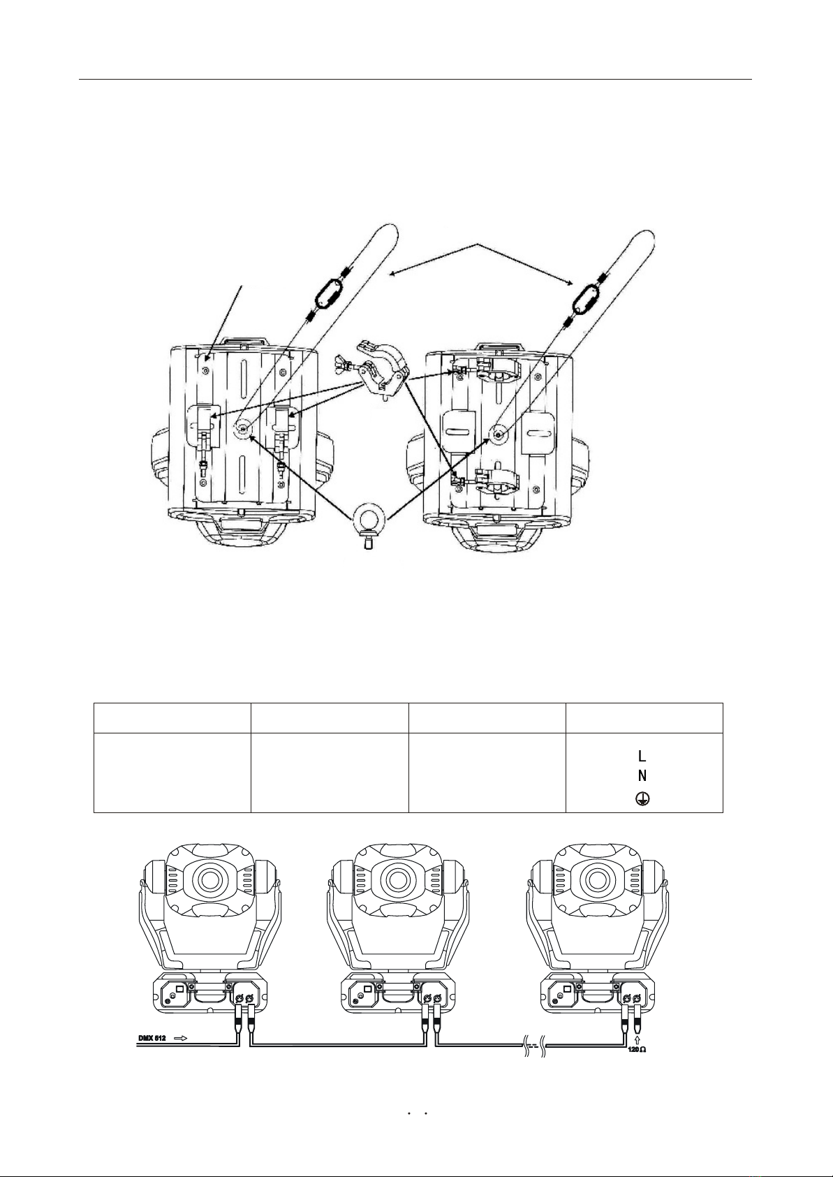
5.5 C on nection to th e mains
V erify th e p ow er supply se ttingsbeforeapplying pow er!
If you wish to change thepow ersupply settings,see thechapterA ppendix.
C onnectthefixture to the mainswith theenclosed pow ercable and plug.
Theearth has to be connected!
Theoccupation ofth e con n ection-cables isas fo llow s:
Pin
Cable (E U ) International
Brown
Lightblue
Yellow /G reen
Black
White
G reen
Live
N eutra l
Earth
Cable (U S )
ØTheprojectorcan beplaced directly on thestage floororrigged in any orientation on a
tru ss withoutaltering itsoperation characteristics.
ØForoverhead use,alwaysinstalla safety-rope thatcan hold atleast10 timesthe weightof
the fixture.You mu
stonly use
safety-ropes with screw -on carabines.Pullthesafety-rope
through thetwoapertureson thebottom ofthe baseand overthe tru ssing system etc.
In sert theend in the carabineand tighten the fixation screw .
5.6 DM X-512con nection/con n ection b etw een fixtures
6
Secure chain
M ounting plate
Eye bolt
Clam p
www.carlosmendoza.com.mx

M ode Function C ondition
Pan movementin positive ornegative dire c tion
YE S --negative dire c tion
Function Table:
YE S --negative dire c tion
Only usea stereo shielded cable and 3-pin XLR-plugs and connectors in orderto connectthe
contro ller with the fixtureoronefixture with another.
DMX-OUTPUT DM X-input
1-G round
2-Signal(-)
3-Signal(+ )
11-G round
2-Signal(-)
3-Signal(+ )
O ccupation ofth e XLR -connection:
XLR m ounting-socket: XLR m ounting-plug:
Caution:A tthelastfixture,the DM X-cable has to be term inated with a term inator.Soldera
120 resistorbetw een Signal(-) and Signal(+ ) into a 3-pin XLR-plug and plug itin the
DM X-outputofthe lastfixture.
Thetransform ofthe controller line of3 pins and 5 pins (plug and socket)
6.ControlB oard O peration
Verticalmovementin positive
ornegative dire c tion
Address code set
Reset
Rainbow colorw heelchange colorlinear
orstepping
Static colorw heelchange colorlinear
orstepping
Static gobo w heelchange gobo linear
orstepping
Y E S --re s e t
YES--linear
YES--linear
YES--linear
Working m ode D M X 512 m ode
Autom atic
Lam p on/off
7
www.carlosmendoza.com.mx
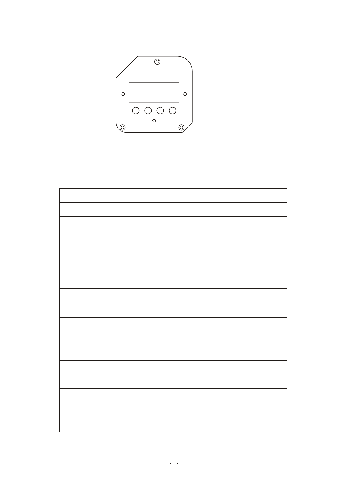
MODE ENTER UP
DOW N
DOW N
7.D M X 512 C hannelFunction
Controlboard operation w ay:
1.Selectworking m ode by pressing M ODE.
2.P ress ENTER to confirm the selection.
3.P ress UP and DOW N to selectworking condition.
4.P ress ENTER to confirm the selection.
LED
1
2
3
4
5
6
7
8
9
10
11
12
13
14
15
16
CHANNEL
PAN
TILT
PAN movementfine adjust
TILT movementfine adjust
Scan speed adjust
Focus,fro m nearto far
Rainbow colorw heel
Static colorw heel
Prism ,prism auto -ro tation
Static gobo w heel
Rotation gobo w heel
G obo ro tate
Iris,fro m big to sm all
Zoom
Beam out/strobe
Dimmer(Lam p on /off)
FUNCTION
8
www.carlosmendoza.com.mx


CHANNEL7:Rainbow color w h eel
200-255
180-199
160-179
140-159
120-139
100-119
80-99
60-79
40-59
20-39
0-19
Value E ffect
Rainbow effect,
Darkorange
Firefly light
Pink
Blue
O range
G reen
Rose
Yellow
Red
White beam
fro m slow to fa st.
79-100
71-78
63-70
56-62
48-55
39-47
32-38
24-31
16-23
8-15
0-7
CHANNEL8:Static color w h eel
234-255
208-233
182-207
156-181
130-155
104-129
78-103
52-77
26-51
0-25
Value E ffect
In crease color
tem perature slip
(6000K )
Sky blue
Lightorange
Pale green
Lightpurple
Pale yellow
Lightred
White beam0-9
10-20
21-30
31-40
41-50
51-60
61-70
71-80
81-90
91-100
Lightblue
D ecrease color
tem perature slip
(3200K )
12
www.carlosmendoza.com.mx

CHANNEL9:Prism p rism auto-rotation
132-255
128-131
5-127
0-4
Stop
Stop
Value E ffect
T h ree-facet prism
reverse ro ta te fr o m
slow to fa st.
T h ree-facet prism
ro ta te fro m slow to
fa st.
53-100
51-52
3-50
0-2
CHANNEL10:Static gobo w heel
200-255
180-199
160-179
140-159
120-139
100-119
80-99
60-79
40-59
20-39
0-19
Gobo9
Gobo8
Gobo7
Gobo6
Gobo5
Gobo4
Gobo3
Gobo2
Gobo1
Value E ffect
Goboflow effect,
fro m slow to fa st.
White beam
79-100
71-78
63-70
56-62
48-55
40-47
32-39
24-31
16-23
8-15
0-7
13
www.carlosmendoza.com.mx
222-255
185-221
148-184
111-147
74-110
37-73
0-36
Value E ffect
Glass gobo 6
Glass gobo 5
Glass gobo 4
Metalgobo 3
Metalgobo 2
Metalgobo 1
White beam
87-100
73-86
59-72
44-58
30-43
15-29
0-14
CHANNEL1 2 :R o ta tion Gobo
159-255
61-158
0-60
R o ta tion gobo r o ta te
fro m slow to fa st
Value E ffect
Rotation gobo reverse
rotate fro m slow to fa st
0-23
62-100
24-61
Gobo-indexing
CHANNEL11:R o ta ting gobo w heel
14
www.carlosmendoza.com.mx

Value E ffect
CHANNEL16:Dimmer(L a m p on /o ff)
0~29
30~39
40~59
60~69
70~255
CHANNEL15:B eam out/stro b e
0-19
20-250
0.0-7
8-98
Value E ffect
strob e, fro m
slow to fa st
Shutter
251-255 99-100 Beam out
16
27.5~100
23.5~27
15.5~23
11.5~15
0~11
Dim m er intensity
fo rm 0% to 100%
Nofunction
Shutter
Lam p on & reset
Lam p o ff & reset
www.carlosmendoza.com.mx

8.Technicalsp ecifications
Voltage A C 210/230/240V ,50/60H z
FuseT10
A C 100/110/120V ,50/60H z
FuseT15
RatedPow er 850W
DM X 512 C hannel 16C H S
Color Tem perature 7000K
Lum inous 49000 LUX
PhilipsM SR 575/2 95V /575W GX9,5
15 18 22
Rigging
-S tands directly on thefloor
-M ounts horizontally orvertically with 2 clam ps
-2 tru ss orientation
-S afety chain/cord attachm entbolt
T em p eratu res
-M a x imum am bienttem perature ta:40
-M a x imum housing tem perature tB (steady state):80
Minimum distan ces
-M in.distance fro m flammable surfaces:0.5m
-M in.distance to lighted object:2.0m
Dimensions and weight
-Length ofbase (including handles):379 mm
-W idth ofyoke:428 mm
-H eight(head horizontal): 476 mm
-W eight(n e t): 36.5 kg
A @ 230V
A @ 110V
Lam p:
OpticalSystem :
- High lum i
nous-efficiency parabolic reflector
- Focuslens and multistep zoom lenses sy stem
-B eam angles:
-A lllensesare anti-reflection coated
17
www.carlosmendoza.com.mx

9.Beam path
18
15 radiation angle
892
9600
223
2400
99
1070
56 Foot-candles
600 LU X
20 Distance(m )
5,27 Diam ete r(m )
15
3,95
10
2,63
5
1,3
3
2
1
0
1
2
3
Beam opening(m )
18 radiation angle
3
2
1
0
1
2
3
Beam opening(m )
773
8320
193
2080
86
930
48 Foot-candles
520 LU X
20 Distance(m )
6,34 Diam ete r(m )
15
4,75
10
3,17
5
1,58
22 radiation angle
583
6270
146
1570
65
700
36 Foot-candles
390 LU X
20 Distance(m )
7,78 Diam ete r(m )
15
5,83
10
3,89
5
1,94
4
3
2
1
0
1
2
3
4
Beam opening(m )
www.carlosmendoza.com.mx
Table of contents
Popular Spotlight manuals by other brands

Exor
Exor MLS2500DWL Installation and commissioning instructions

Claypaky
Claypaky ALPHA SPOT HPE 1500 instruction manual

LIVARNO LUX
LIVARNO LUX HG00108A Assembly, operating and safety instructions

IMG STAGE LINE
IMG STAGE LINE PARC-56/RGB instruction manual

Heath Zenith
Heath Zenith 7162 manual

LIVARNO LUX
LIVARNO LUX LLES B2 manual


