Parameter
Power up
Response
Off Delay
On Range
Off Range
1st Zone
2nd Zone
3rd Zone
4th Zone
Corridor 1
Corridor 2
Global 1 Rx
Global 2 Rx
Passive Photocell
Manual Input
Start Lamps
Entry Scene
Bright-Out
Fade to Of*
Vacant
Dimming
Set-Point Low
Set-Point High
Default
Setting
ON
AUTO
20 min
20
100%
-
-
-
-
-
-
NO
NO
YES
LOCAL
MAX
1
NO
NO
OFF
100%
766
1022
Options
ON/OFF
Auto/Semi-auto
1min-96hrs or Disabled
1-100
10-100% in 10% increments
A 1-100
A 1-100
A 1-100
Address 1-100
1-100 Building Address Span
1-100 Building Address Span
YES/NO
YES/NO
YES/NO
LOCAL/SHARE
MAX/MIN
1-6
YES/NO
YES/NO
10 Exit Scenes
Regulate 50-100%
0-1023
0-1023
ddress
ddress
ddress
Options
Each of these settings
can be re-programmed,
if desired, by use of the
infrared programming
tool HP2000.
- Manual Input is only
available via the
Wireless OneSwitch
facility of the
MLS2500DWL(F) and
MLS2500DALIWL(F).
See Application Note
AN4021 for further
information
Commissioning
The units are supplied with the factory default settings, shown below, which render commissioning, apart from
zoning, unnecessary in many applications. To allocate to zone(s), effected via the MLS Bus signals, and make use
of the programmable settings, an infrared commissioning tool is required (the HP2000). A ten-second time delay is
selectable to aid commissioning.
Sensitivity to Movement
While the factory
Factory Default Settings
settings will be correct for many applications, the sensitivity can be adjusted if required.
ON Sensitivity (ON Range): This sets the detector’s range when the lights are ON. Choose setting from 1-100
where 1 is lowest and 100 is maximum. (Note: Choose the lowest level possible to give adequate detection.)
OFF Sensitivity (OFF Range): This sets the detector’s range when the lights are OFF. Choose % setting from 10%
to 100% where 10% = 10% of ON Sensitivity and 100% = same as ON Sensitivity. This is an approximation and
should be tested on site during commissioning.
Like all programmable parameters, the sensitivity settings will be retained in the event of a power failure and can be
re-programmed any number of times.
Setting the Photocell
The regulating light level is set using either a hand-held controller (HC5) or via the infrared programmer HP2000.
i) Regulating Only
Using a light meter, set the required light level and choose Set Light Level in the USER REMOTE menu on the
HP2000. A snapshot of the current conditions is taken by the detector and stored as the regulating set point -
Set-Point Low in the table above. When used with regulating ballasts, the photocell may hold lights off upon entry
should sufficient natural light be available. It will only turn lights off in an occupied area if Bright-Out is set to YES and
the light level exceeds the Set-Point High setting for a period.
Please note that, although configurable as a regulating photocell, providing closed-loop dimming according to
daylight levels, it is probable that the typical corner-of-room location dictated by the needs of the presence detection
function will compromise the detector's ability to achieve precise light levels on the working plane, due to the effects
of strong reflections of light of all origins from the walls and/or of direct daylight from any windows in its field of view.
Fixing
1. The Digital Mid Range LightSpot is an extremely sensitive movement detector; it is essential therefore that it
be installed on a rigid surface that will not itself be subject to any movement or vibration.
2. Before isolating the circuits to be switched, check that all lighting is fully operational and that there is no moving
equipment or machinery within the monitored area which may cause nuisance switching.
3. Position the detector where it has a good forward “view” of the area to be controlled. Ideal mounting location is
normally in a corner by the entrance or at one end of a corridor at a height of 2.5 to 4m. Do not mount within
25cm of a fluorescent fitting.
4a. MLS2500D - Surface version
Separate the detector from its back-box by loosening the locking screw so that approximately 3mm of thread is
visible and then twisting the detector off the back-box. Note the arrow symbol moulded into the bottom of the
back-box. The fixing holes allow for mounting on a BESA box or direct to a rigid surface. Secure the back-box
firmly to a rigid surface so that the arrow points into the controlled area.
4b. MLS2500DF- Semi-flush version
Use a hole saw to drill a 76mm hole into the ceiling tile. The flush ring is designed to clamp the tile between its
two halves. Loosen the locking screw so that approximately 3mm of thread is visible and remove the bottom
half of the flush ring. With the detector in the ceiling, pointing towards the area to be controlled, fit the bottom
half of the flush ring to the assembly. Depending on the thickness of the ceiling tile, screws longer than those
supplied may be required to hold the two halves of the flush ring together.
It is recommended that Mid Range detectors be ceiling mounted. Where this is not possible, the wall-mounting kit
(WMK - see cover page) must be used.
Only suitably qualified personnel should install this equipment.
Please note that this product uses microwave technology to detect occupancy and is not recommended for
applications where there are large areas of metal, e.g. metal ceiling or panelling, as unpredictable sensitivity
may result.
Also, microwave presence detection is not completely attenuated by materials such as plasterboard, wood and
glass, so the possibility of unwanted presence detection through office partitions should be considered when
determining detector positioning and sensitivity settings within the intended application.
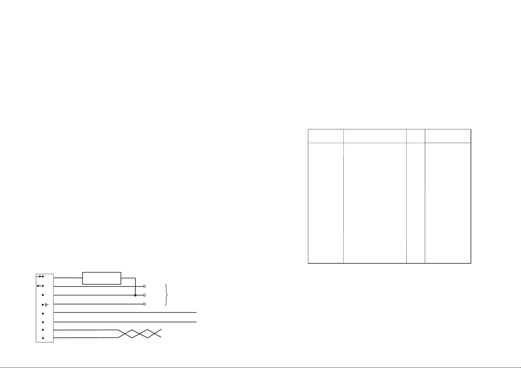
Electrical Connections
Digital Mid Range LightSpot should be connected in accordance with the diagram below
Digital Mid Range LightSpot is designed to control up to 25 DSI or DALI ballasts, a switched load of up to 10 Amps or
a combination of the two. When controlling DSI or DALI ballasts the ballast types must not be mixed. The DSI or
DALI input terminals on the ballasts should be connected in parallel with each other and to the Polarity-Free Digital
Output terminals of the MLS2500D. Each DSI or DALI luminaire is controlled completely by its digital input and
therefore would normally have a permanent power supply. Turning the power off to some lights within a control circuit
will not affect the operation of those lights that remain powered and under the control of the MLS2500D.
When switching via the relay output, multiple MLS2500Ds' relay outputs may be connected in parallel provided the
controlled load does not exceed 10 Amps. If digital ballasts are also being controlled, the digital outputs from
different detectors must never be connected one to another, even if they are of the same type.
LL
N
1 2 34
5
6
D
78
MD
M
(MLS Bus)
(Digital Out)
SW
W4364A
Digital Mid Range LightSpot
Always check product label before wiring
Live Out
Live In
Neutral
Earth
D1
D2
MLS 1
MLS 2
Mains
Supply
Live
Neutral
Earth
10 Amps Maximum
SWITCHED LOAD
MLS 2-core Bus Cable Do NOT connect to Mains
Note: A means of disconnection must be incorporated into the fixed wiring in accordance with the current wiring regulations.
Digital Dimming Signal Pair to Ballasts


