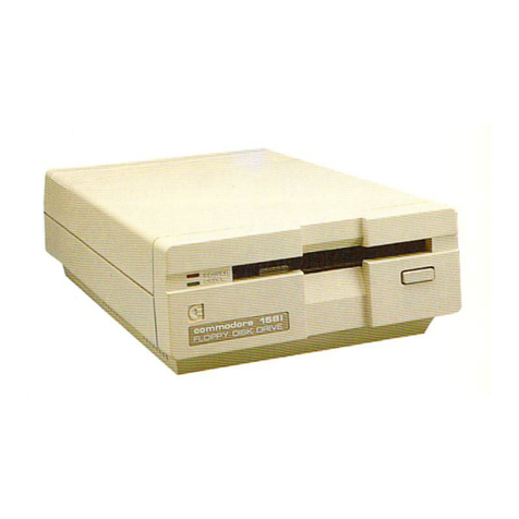
Shugart Bi-Compliant SAB850 Installation and operation manual

SA850/851
Bi-Compliant™
Double
Sided
Diskette
Storage
Drive
~@Shugart

TABLE OF CONTENTS
1.0 Introduction
1.1
General Description .
1.2 Specification
Summary.
. .
1.2.1
Performance Specifications
..
1.2.2 Functional Specifications.
1.2.2 Physical Specifications
1.2.4 Reliability Specifications
2.0 Functional
Characteristics.
2.1
General Operation .
2.2 Read/Write
'and
Control Electronics .
2.3 Drive Mechanism
2.4 Positioning
Mechanism.
2.5 Read/Write Heads .
3.0 Functional Operations
3.1
Power Sequencing
3.2 Drive Selection
3.3 Track Accessing
3.3.1
Step Out .
3.3.2 Step
In
3.4 Side Selection .
3.5 Read Operation
..
3.6 Write Operation
..
3.7 Sequence of Events .
4.0 Electrical Interface
..
4.1
Signal
Interface.
. ....... .............
..
. .
4.1.1
InputLines .
4.1.1.1 Input Line Termination.
4.1.1.2
DriveSelect1-4.
""""
4.1.1.3 Side Select . .
4.1.1.4 Direction Select. .
.. .. ..
4.1.1.5
Step.
. .
4.1.1.6 Write
Gate.
. .
4.1.1.7 Write Data ...
4.1.1.8 Head Load (Alternate Input) . .
4.1.1.9
In
Use (Alternate Input) .
4.1.1.10 Write Current Switch/Active Read Compensation.
4.1.2 Output
Lines.
. .
4.1.2.1 Track 00 . ........... . .
4.1.2.2
Index.
............................ . .
4.1.2.3 Sector
(SA851
only) .
4.1.2.4 Ready
..
4.1.2.5 Read Data .
4.1.2.6 Sep Data
(SA851
only) . .
..
4.1.2.7 SepClock(SA851 only) .
4.1.2.8 Write Protect
..
4.1.2.9 Disk Change (Optional Input) .
4.1
.2.10 Two Sided (Optional Input)
..
4.1.3 Alternate I/O Pins .
4.2 Power
Interface..
. .
4.2.1
AC
Power
4.2.2
DC
Power.
1
1
2
2
2
3
3
4
4
4
4
4
6
..
.....
7
""
7
7
7
7
.......
7
9
..
11
·
12
·
14
.16
·16
·16
·17
17
........
18
·18
·18
.18
.
18
·18
18
·19
·19
·19
·
..
19
·19
·19
·
..
20
.
.20
·..............20
·
..
20
·
...
20
·
..
20
.20
·
21
21
·
21

TABLE OF CONTENTS CONTINUED
5.0 Physical Interface
..
5.1
J1/P1
Connector
5.2 J5/P5 Connector
5.3 J4/P4 Connector
6.0 Drive Physical Specifications
..
13.1
Drive Dimensions
6.2 Mounting Recommendations
13.3
Chassis
Slide.
6.4 Decorative Face Plate
..
7.0 Customer Installable
Options.
7.1
Select Drive Without Loading Heads or Enabling Stepper
7.2
Select Drive and Enable Stepper Without Loading Heads
..
7.3
Loads Heads Without Selecting Drive or Enabling Stepper.
7.4 Radial Ready
...
7.5 Radial Index/Sector .
7.6
In
Use Alternate Input (Activity LED) .
7.7 Write Protect Optional Use .
7.8 Disk Change (Optional Output)
7.9 Side Selection Using Direction Select
7.10 Side Selection Using Drive Select
..
7.11
Door Lock Latch
7.12 Two Sided (Optional Output)
..
7.13 Head Current Switch/Active Read Compensation.
7.13.1 Head Current Switch
7.13.2 Active Read Filter
..
7.14 Ready Standard/Ready Modified
..
7.15 Head Load Latch
..
8.0 Operation Procedures
8.1
Diskette Loading and Handling
..
8.2 Write Protect -SA150/151 Diskettes
...
8.3 Write Protect, IBM Diskettes.
9.0 Error Detection and Correction
9.1
Write
Error.
9.2 Read
Error.
10.0 Reshipment Precaution
II
·
.....
22
.............
22
·
.....
23
·
..
23
·
..
24
............
24
·
.....
24
·
..
27
·
..
27
·
..
28
·32
·32
·33
.35
·36
·
..
37
·37
·38
·39
·40
·
41
·
41
·
..
42
·42
·42
·42
·43
..
45
·
..
45
·
....
46
·
..
46
·47
.47
·47
·47

LIST
OF
ILLUSTRATIONS
Figure
1.
SA850/851 Functional Diagram .
2.
Track Access Timing
..
3.
Read Initiate Timing. . . . .
4.
FM, MFM and
M2FM
Code Comparisons
5.
Read Signal Timing (FM Encoding)
....
6.
Write Initiate Timing .
7.
Write Data Timing (FM Encoding)
..
8.
General Control and Data Timing Requirements.
9.
Interface Connections. . . .
10. Interface Signal Driver/Receiver .
11. Index Timing .
12. Sector Timing . .
13.
J1
Connector
Dimensions.
........ . .
14. J5
Connector.
. .
15. J4
Connector.
........... . .
16. Interface Connector-Physical Location Diagram.
17. Recommended Mounting
.,
.
18.
SA850/851 Diskette Storage Drive Dimensions
19.
SA850/851 RDimensions .
20.
Slide Mounting Dimensions .
21. MLC 10 Component Locations (PIN 25188)
.....
22.
MLC
11
PCB
Component Locations (PIN 25200) .
23. Select Drive Without Loading Head
Circuit.
: .
24.
Stepper Motor Enable Circuit . .
25.
Load Head Without Selecting Drive or Enabling Stepper Circuit
..
26.
Radial Ready Circuit
27.
Radiallndex/Sector Circuit .
28.
In
Use/Activity
LED
Circuit
29. Write Protect Circuit
30. Disk Change Timing.
31. Disk Change Circuit.
32. Side Selection, Using Direction Select
33. Side Selection, Using Drive Select
34. Door Lock Latch Control
...
35.
IW
Jumper Option
36.
Head Load Latch Using Head Load.
37. Head Load Latch Using
In
Use
38. Loading SA850/851
39. Diskette Write
Protected.
40.
Write Inhibit Notch Specifications.
41. Package Assembly
42. Pallet Loading
"'
5
8
9
.10
10
· . 13
13
14
15
17
19
.20
.
..
22
·
.23
23
23
·
.24
.25
· .
26
27
30
· .
31
·
.33
·
.34
34
35
36
37
37
~8
38
39
.40
· .
41
·
.42
· . 43
44
45
46
46
· .
48
49

1.0 INTRODUCTION
1.1
GENERAL DESCRIPTION
The SA850/851 diskette storage drives are enhanced double-headed versions of the standard Shugart
SA800/801 drives. SA850/851 drives provide up to four times the on-line storage capacity, faster access
time, and lower heat dissipation along with improved reliability and maintainability.
SA850/851 drives read and write
in
single or double density on standard diskettes and
on
both sides of two-
sided diskettes. The drives are exactly the same size as Shugart SA800/801 drives and are plug compatible.
The SA850/851 drives are also media compatible with IBM 3740 and S/32 single-sided drives as well as IBM
4964 and 3600 series two-sided units.
The proprietary
Fasflex™
actuator utilizes aflexible metal band for sure low friction head movement and a
fast 3ms track-to-track access time.
In
addition, Shugart's
Bi-Compliant™
read/write head assembly pro-
vides superior compliance resulting
in
excellent data integrity.
Other valuable features include: programmable door lock and write protect plus dual index sensor to dif-
ferentiate between single and two-sided diskettes.
The SA850/851 will prove highly cost-effective
in
applications such
as:
intelligent terminals, minicom-
puter/microcomputer systems, small business systems as well as word processing systems and intelligent
calculators.
Key Features
•Storage capacity of up to four times that of SA800 and other standard floppy drives.
•Single or double density (standard).
•Same physical size as standard SA800/801 product family.
•SA800/801 I/O compatibility.
•Improved access time over standard drives - 3 ms track-to-track.
•Proprietary Fasflex™actuator.
•Bi-Compliant read/write head assembly.
•Write protect and programmable door lock are standard for improved data security.
•Lower Heat dissipation.
•Improved
AC
connector.

'1.2
SPECIFICATION SUMMARY
'1.2.1
PERFORMANCE SPECIFICATIONS
Capacity
Unformatted
Per Disk
Per Surface
Per Track
IBM Format (128 byte sectors)
Per Disk
Per Surface
Per Track
Transfer Rate
Latency (Avg.)
Access
Time
Track to Track
Average (including settling)
Settling Time
Head Load Time
Single Density
800 kilobytes
400
ki
lobytes
5.2 kilobytes
500 kilobytes
250 kilobytes
3.3 kilobytes
250 kilobits/sec.
83 ms
3
ms
91
ms
15
ms
50 ms
Double Density
1600 kilobytes
800 kilobytes
10.4 kilobytes
1000 kilobytes
500 kilobytes
6.66 kilobytes
500 kilobits/sec,
83 ms
3ms
91
ms
15 ms
50
ms
'1.2.2
FUNCTIONAL SPECIFICATIONS
Single Density Double Density
I~otational
Speed 360 rpm 360 rpm
I~ecording
Density 3408 bpi 6816 bpi
(inside track)
Flux Density 6816 fci 6816 fci
Track Density 48 tpi 48 tpi
Cylinders
77 77
Tracks 154 154
Heads 22
Physical Sectors
SA850/R 00
SA851/R 32 32
Index 11
Encoding Method FM MFM/M2FM
Media Requirements
SA850 SA150/lBM SA150/lBM
Diskette 2D Diskette 2D
SA851
SA151 SA151
Alignment Diskette SA122 SA122
2

1.2.3 PHYSICAL SPECIFICATIONS
Storage
-8°
to 117°F
1to
95%
No condensation
Shipping
-40° to 144°F
1to
95%
No condensation
Operating
40° to 115°F
20 to
80%
85°F
Environment Limits
Ambient Temperature
Relative Humidity
Maximum Wet Bulb
AC
Power Requirements
50/60 Hz ±0.5 Hz
100/115
VAC
Installations =85 to 127V @.35A Max.
200/230
VAC
Installations =170 to 253V @.25A Max.
DC
Voltage Requirements
+24VDC ±10%1.0A Max.
+
5VDC±
5%
1.1A Max.
Mechanical Dimensions (exlusive of front panel)
SA850R/851 RSA850/851
Height =4.62 in. (117 mm) 4.62 in. (117 mm)
Width =8.55 in. (217 mm) 9.50 in.
(241
mm)
Depth =14.25 in. (362 mm) 14.25 in. (362 mm)
Heat Dissipation Typical Maximum
BTU/Hr. 200 245
Watts 60 72
1.2.4 RELIABILITY SPECIFICATIONS
MTBF:
MTTR:
Component Life:
Error Rates:
Soft Read Errors:
Hard Read Errors:
Seek Errors:
Media Life:
Passes per Track
Insertions:
5000
POH
under heavy usage.
8000
POH
under typical usage.
30 minutes
15,000
POH
1per 109bits read.
1per 10
12
bits read.
1per 106seeks.
3.5 x10⁶
30,000 +
3

2.0 FUNCTIONAL CHARACTERISITICS
2.1
GENERAL OPERATION
SAB50/851
Diskette Storage Drives consist of read/write and control electronics, drive mechanism, Bi-
Compliant read/write heads and atrack positioning mechanism. These components perform the following
functions:
Interpret and generate control signals.
Move read/write heads to the selected track.
Read and write data.
The
Fasflex™
Head Positioning Actuator positions the read/write heads to the desired track
on
the disl<ette.
ThE!
Head Load Solenoid loads the read/write heads against the diskette and data may then
be
recorded
on
or read from the diskette.
2.2 READ/WRITE AND CONTROL ELECTRONICS
The
electronics are packaged
on
one
PCB.
The
PCB
contains:
1.
Index Detector Circuits (Sector/Index for 851)
2.
Head Position Actuator Driver.
3.
Head Load Solenoid Driver.
4.
Read/Write Amplifier and Transition Detector.
5.
Data/Clock Separation Circuits
(SA851
only).
6.
Write Protect
7.
Drive Ready Detector Circuit.
8.
Drive Select Circuits.
9.
Side Select Circuit.
10.
In
Use and Door Lock Circuits.
11.
Write Current Switching/Read Compensation.
2.3 DRIVE MECHANISM
The
Diskette drive motor rotates the spindle at 360 rpm through abelt-drive system. 50 or 60
Hz
power is ac-
commodated by changing the drive pull.ey and belt. Aregistration hub, centered
on
the face of the spindle,
positions the Diskette. Aclamp that moves
in
conjunction with the cartridge guide fixes the Diskette
10
the
registration hub.
2.4 POSITIONING
MECHANISM
The
read/write heads are accurately positioned by Fasflex™metal band/stepping motor actuator systom. A
precision stepping motor is used to precisely position the head/carriage assembly through the use of auni-
qUE~
metal band/capstan concept. Each 3.60rotation of the stepping motor moves the read/write head one
track
in
discrete increments.
4

ACTIVITY LIGHT
SIDE
SELECTI POWER ON RESET
//
-'l
//
-'l
-'l'
ij
ij
~
~
-'l
ij
WRITE PROTECT LED \
II
//"
"
",/
"",'"
II
",/
II
",'"
II
""
II
//
II
,,/
II
/""
II
//
II
//
II
//
II
",,/
It""
TRACK 00 DETECTOR
TRACK 00 LED
INDEX DETECTOR
INDEX LED
HEAD 1
HEAD 0READ
LOGIC
WRITE
LOGIC
CONTROL
LOGIC
READ
DATA
SEP DATA
(FM)
SEP CLOCK
(FM)
WRITE DATA
WRITE GATE
WRITE PROTECT
SIDE SELECT
IN
USE LED
HEAD LOAD
(OPTIONAl)
STEP
DIRECTION/SIDE SELECT
(OPTIONAl)
DRIVE SELECT
TRACK 00
'INDEX
READY'
SECTOR (851)
ALTERNATE I/O
(3
LINES)
TWO SIDED
(OPTIONAl)
DISK CHANGE
LD
FIGURE
1.
SA850/851 FUNCTIONAL DIAGRAM

2.5 READ/WRITE HEADS
The proprietary heads are asingle element ceramic read/write head with straddle erase elements to provide
erased areas between data tracks. Thus normal interchange tolerances between media and drives will not
degrade the signal to noise ratio and insures diskette interchangeability.
The
diskette
is
held
in
aplane perpendicular to the read/write heads by aplaten located
on
the base casting.
This precise registration assures perfect compliance with the read/write heads. The flexure-mounted head
is
loaded against its rigidly mounted counterpart via the head load solenoid. The read/write heads are
in
clirect
contact with the diskette.
The
head surface has been designed to obtain maximum signal transfer to and
from the magnetic surface of the diskette.
6

3.0 FUNCTIONAL OPERATIONS
3.1
POWER SEQUENCING
Applying
AC
and
DC
power to the SA850/851 can be done
in
any sequence, however, once
AC
power has
been applied, a 2 second delay must be introduced before any Read or Write operation
is
attempted. This
delay
is
for stabilization of the Diskette rotational speed. Also, after application of
DC
power, a90 millise-
cond delay must be introduced before aRead, Write, or Seek operation or before the control output signals
are valid. After powering on, initial position of the read/write heads with respect to data tracks is indeter-
minable.
In
order to assure proper positioning of the read/write heads prior to any read/write operation after
powering on, aStep Out operation should be performed until the Track 00 indicator becomes active.
3.2 DRIVE SELECTION
Drive selection occurs when adrive's Drive Select line
is
activated. Only the drive with this line active will
respond to input lines or gate output lines. Under normal operation, the Drive Select line will load the
read/write head, apply power to the stepper motor, enable the input lines and output lines, light the Activity
LED
on
the front of the drive and lock the door. Optional modes of drive selection are discussed
in
Section
7.
3.3 TRACK ACCESSING
Seeking the read/write head from one track to another is accomplished by:
a.
Activating Drive Select line
..
b.
Selecting desired direction utilizing Direction Select line.
c.
Write Gate being inactive.
d.
PUlsing the Step line.
Multiple track accessing
is
accomplished by repeated pUlsing of the Step line until the desired track has
been reached. Each pulse
on
the Step line will cause the read/write heads to move one track either
in
or out
depending
on
the Direction Select line. Head movement
is
initiated
on
the trailing edge of the Step Pulse.
3.3.1
STEP OUT
With the Direction Select line at aplus logic level (2.5V to 5.25V) apulse
on
the Step line will cause the
read/write heads to move one track away from the center of the disk. The pUlse(s) applied to the Step line
and the Direction Select line must have the timing characteristics shown
in
Figure
2.
3.3.2 STEP IN
With the Direction Select line at aminus logic level
(OV
to AV), apulse
on
the Step line will cause the
read/write heads to move one track closer to the center of the disk. The pUlse(s) applied to the Step line must
have the timing characteristics shown
in
Figure
2.
7

DC POWER
DRIVE SELECT
------~ss"'r--------
--------""""'55
...
-------
OUT
DIRECTION SELECT
STEP
....
IN
~((
....
---
)J
FIGURE
2.
TRACK ACCESS TIMING
8
j.-
3
ms
MIN

3.4 SIDE SELECTION
In
the standard SA850/851 ,head selection
is
controlled via the I/O signal line designated Side select. Aplus
logic level on the Side Select line selects the read/write head
on
the side 0surface of the diskette. Aminus
logic level selects the side 1read/write head. When switching from one side to the other, a 1
OOIlS
delay
is
re-
quired after Side Select changes state before aread or write operation can be initiated. Figure 3shows the
use of Side Select prior to aread operation.
Two jumper-selectable Side Select options are also available. Either of these can be implemented to make
use of existing controller and cable harness design. These options are described fully
in
Section
7.
-------------"'ss~---
DC POWER
DR!VE SELECT I
S(
Ij
STEP
SS
1
l::J
90 ms
1-
100
•8
MIN
SIDE SELECT
I~
II
~
WRITE GATE I
VALID READ DATA
~~~NMS
.....
--
50
MS MIN
.....
---
90 MS
MIN*
---
.....
*2
SECONDS IF AC
AND
DC POWER ARE APPLIED AT THE SAME TIME
FIGURE
3.
READ
IN/TATE TIMING
9
14-
__
50
fLS
MIN

_________
.-.l
800o
__
C:=J
BIT
CELLS
D
FM
I
_.--.~
I
I
J
J
D
D
D
D
D
D
D
D
D'
DD
D
D
4/5F
L
FIGURE
4.
FM, MFM AND M2FM CODE COMPARISONS
RE,A,D
DATA
I
A B
SEP
DATA
(851).
__
~I~
__
-;I
ONLY
4.00p.s
NOM.
~200±50ns
LJ
2.00p.s
NOM.
u
2.00p.s
NOM.
u
A =
LEADING
EDGE
OF
BIT
MAY
BE ±
400ns
FROM
ITS
NOMINAL
POSITION.
B=
LEADING
EDGE
OF
BIT
MAY
BE ±
200ns
FROM
ITS
NOMINAL
POSITION.
FIGURE
5.
READ SIGNAL TIMING (FM ENCODING)
10

3.5 READ OPERATION
Reading data from the SA850/851 Diskette Storage drive
is
accomplished by:
a.
Activating Drive Select line.
b.
Selecting head.
c. Write Gate being inactive.
The timing relationships required to initiate aread sequence are shown
in
Figure
3.
These timing specifica-
tions are required
in
order to guarantee that the read/write head position has stabilized prior to reading.
The coding scheme of the recorded data can be FM, MFM or M2FM. The first of these, FM, provides single-
density recording. The superior efficiency of the other two codes permit their bit cell period to be
V2
that of
the
FM
code, thereby providing double-density recording. Differences among FM, MFM and
M2FM
encoding
are concerned with the use of clock bits
in
the write data stream.
FM
encoding rules specify aclock bit at the start of every bit cell. See Figure 4. MFM and
M2FM
encoding
rules allow clock bits to be omitted from some bit cells, with the following prerequisites:
a.
MFM -The clock bit is omitted from the current bit cell if either the preceding bit cell or the current
bit cell contains adata bit. See Figure 4.
b.
M2FM
-The clock bit
is
omitted from the current bit cell if the preceding bit cell contained any bit
(clock or data) or if the current bit cell contains adata bit. See Figure 4.
In
all three of these encoding schemes, clock bits are written at the start of their respective bit cells and data
bits at the center of their bit cells.
The timing of the read signals, Read Data, Separated Data and Separated Clock are shown
in
Figure 5(FM
encoding).
In
the standard
SA851
,data separation of
FM
data is performed by the drive electronics. Data bits are
presented to the controller
on
the
Sep
Data line and clock bits are presented
on
the Sep Clock line.
In
systems using the SA850 or when MFM/M2FM encoding
is
used, data separation
is
performed outside the
drive.
IN
such cases, the Read Data line carries both clock bits and data bits. Separation
is
MFM or
M2FM
encoded read data should
be
controlled by aphase-locked loop oscillator (PLO) circuit.
For additional information regarding the use 'of MFM and
M2FM
encoding with SA850/851 drives, refer to
Shugart Associates' Double Density Design Guide.
11

3.18
WRITE OPERATION
Writing data to the SA850/851
is
accomplished
by:
a.
Activating the Drive Select line.
b.
Selecting head.
c.
Activating the Write Gate line.
d.
Pulsing the Write Data line with the data
to
be
written.
e.
Head Current switching.
The
timing relationships required to initiate awrite data sequence are shown
in
Figure
6.
These timing
specifications are required
in
order to guarantee that the read/write head position has stabilized prior to
writing.
Write data encoding can
be
FM,
MFM or
M2FM.
If either double-frequency encoding scheme
is
used (MFM
or
M2FM)
the write data should be precompensated to counter the effects of bit shift. The amount
and
direc-
tion of compensation required for any given bit
in
the data stream depends
on
the pattern it forms with near-
by
bits.
For more details regarding data encoding and formatting for SA850/851 drives, refer to Shugart Associates'
Double Density Design Guide.
12

u
DC POWER
DRIVE SELECT
_f
r-
9°
1
MS
MIN'-I
r-
50MSMIN
-I
--U,.....--~I
----
---I
r-
18
MS
MIN
WRITE GATE
-------------IL..
_
-I
1-
4.00
"8
MAX
-----U
U
STEP
WRITE DATA
*2
SECONDS IF AC
AND
DC POWER ARE APPLIED AT SAME TIME.
FIGURE
6.
WRITE INITIATE
TIMING
WRITE DATA
(FM)
........
---
1.--150n8
MIN
1100ns
MAX
I.--
4.00"s ±20
ns
--l-
2.00"s
--I
±
10ns
FIGURE
7.
WRITE DATA TIMING (FM ENCODING)
13

3.7 SEQUENCE OF EVENTS
The timing diagram shown
in
Figure 8shows the necessary sequence of events with associated timing
restrictions for proper operation.
AC
POWER .JI _2
SE~
__
I
ra-
MAX
--,
"'""-\
""~
----------
....
'j
<....
,--------_._---
.-J
.....
------S}
't-.
--------'lS~
~
....
~
---------'~~
....
----_._-
DC
POWER
--I
I----
90 ms
MIN'
VJ\L1D
CONTROL
~I
OUTPUT SIGNALS II.
HI--500ns
MAX
DFllVE SELECT 1--I-------
....
~~'t-----------\~
t'to,
_
1"","---
I.-1
00Jts
::I
IMAX I
VALID READ
D)HA
SIGNAL
WRITE DATA
SIDE SELECT
DIRECTION SELECT** I
-!
I--
1"s
MIN
~
I-
1"s
MIN
~\
--.J
I--
1Jts
MIN
~
~
1Jts
MIN
STEP
--';"'--lJnj
~
......
---......(~\-------.---
---.J
p:.~~;sll
3ms MIN
-l
I--
I
II
rc
--.I
~18mS
WRITE GATE
'\'~
1-'
..
I"
I
9LsM11~0:;MIN
:!I
~H
I..
I
NOTE1:
I
4Jts
MAX I
I ,
t--
ru-
......
------.---
-I
~18msMIN
~
~50"SMIN
I
FNOTE1:4.n.P~
~~-
r-:.
90 ms MAX
~
*2 SECONDS IF AC AND
DC
POWER ARE APPLIED AT SAME TIME.
**WHEN
CHANGING DIRECTION ON THE HEAD A15
MS
DELAY MUST
BE
INTRODUCED.
NOTE
150 ms minimum delay must be introduced after Drive
Select to allow for proper head load settling. If stepper
power is to be applied independent
of
Head Load, then
a15 ms minimum delay must be introduced to allow for
stepper settling. See section 7on optional
customer
installable features.
FIGURE
8.
GENERAL CONTROL AND DATA TIMING REQUIREMENTS
14

MAX
FEET
10
FT
FLAT
RIBBON
OR
20
FT
TWISTED PAIR SA850/851
2
J1
WRITE
CURRENT
SWITCH/ACTIVE READ
COMPENSATION
1
10 9
DISK
CHANGE'
12
11
SIDE SELECT
14
13
IN
USE'
16
15
HEAD
LOAD'
18 11
INDEX
20
19
READY
22
21
SECTOR (851
ONL
Yl
24 23
DRIVE SELECT 1(SIDE SELECT OPT)
26
25
DRIVE SELECT 2(SIDE SELECT OPT) 28 27
DRIVE SELECT 3(SIDE SELECT OPT)
30
29
31
32
DIRECTION
SEU::CT (SIDE SELECT OPT) 14 33
STEP
36
35
-.,
WRITE
DATA
38 37
WRITE GATE
40
39
TRACK
00
42
41
WRITE PROTECT 44 43
READ
DATA
45
46
SEP
DATA
(851
ONLY)
48
47
-SEP
CLOCK
(851
ONL
Yl
50
49
,..
+5
VDC 5J5 6
.I
.L
-:
DCGND
-24
VDC
12
X+24 VRETURN
-==
.....
,J4
ACINPUT
1
FRAME
GROUND
~~
ACINPUT
AC
GND
r,.,'fT1
FRAME
GND
TWISTED PAIR
*These lines
are
alternate
input/output
lines and
they
are
enabled
by
jumper
plugs,
Reference
Section 7for
uses
of
these lines, Not shown
are
pins
4,
6
and
8
which
are
alternate
I/O pins.
FIGURE
9,
INTERFACE
CONNECTIONS
15

4.0 ELECTRICAL INTERFACE
The interlace of the SA850/851 Diskette drive can be divided into two categories:
1.
Signal
2~.
Power
The following sections provide the electrical definition for each line.
F~eference
Figure 9for all interface connections.
4.1
SIGNAL INTERFACE
The signal interface consists of two categories:
1.
Control
2. Data transfer
All lines
in
the signal interface are digital
in
nature and either provide signals to the drive (input),
or
provide
signals to the host (output), via interface
connector
P1/J1.
4.1.1
INPUT LINES
There are thirteen (13) signal input lines, ten (10) are standard and three (3) are user installable options
(reference section 7).
TIle input signals are of two types, those intended to be mUltiplexed
in
amultiple drive system and those
which will perform the multiplexing. The input signals to be mUltiplexed are:
1.
Direction Select
2"
Step
3.
Write Data
4.
Write Gate
5.
Side Select
6.
Head Current Switch/Active Read Compensation
7.
In
Use
8.
Head Load
The input signals which are intended to do the multiplexing are:
1.
Drive Select 1
2. Drive Select 2
3.
Drive Select 3
4.
Drive Select 4
16
This manual suits for next models
1
Table of contents
Other Shugart Floppy Disk Drive manuals