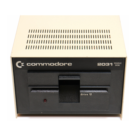
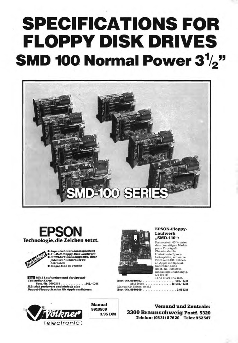
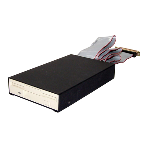
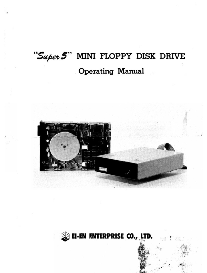
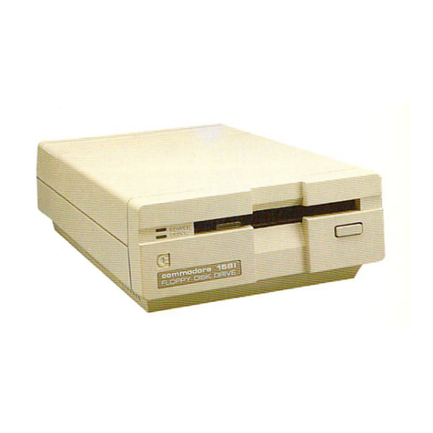
Shugart SA 400 minifloppy User manual

SA400
CQ
m
minifloppyTM
~
Diskette
Storage
Drive
~~
~
2)
~
~
C=:=J

SA400
CQ
m
minifloppyTM
~
Diskette
Storage
Drive
~~
@)
2)
~
@)
C=:=J
©
Copyright
1977 Shugart Associates

PREFACE
This manual describes the electrical and mechani-
cal characteristics
of
the SA400 minifloppyr\fdrive
required
by
customers who purchase it
as
an
OEM device.
It
contains the timing, electrical and
mechanical specifications; recommended formats
and circuitry necessary
to
interface
it
to
a
host
controller/formatter.
For maintenance information, reference the
SA400 Service Manual, P
/N
54096.
™Minifloppy, minidiskette and ministreaker are
Shugart Associates trademarks.

Table
of
Contents
1.0
2.0
3.0
4.0
Introduction . . . . . . . . .
1.1
Specification Summary . .
1.1.1 Performance Specifications
1.1.2 Functional Specifications
1.1.3 Physical Specifications. .
1.1.4 Reliability Specifications.
Functional Characteristics . . .
2.1
General Operation . . .
2:2 Read/Write and Control Electronics
2.3 Drive Mechanism. . . . . . .
2.4 R/W
Head
Positioning Mechanism
2.5 Read/Write
Head.
2.6 Recording Format
Functional Operations. .
3.1
Power Sequencing
3.2 Drive Selection
3.3
Motor
On.
. . .
3.4 Track Accessing .
3.4.1 Step
Out.
. .
3.4.2 Step
In.
. . .
3.5
Read
Operation
3.6 Write Operation
3.7 Sequence
of
Events
3.8 Multiplex
Option.
3.8.1 Drive Selection
Electrical Interface . .
4.1
Signal Interface
4.1.1
Input
Lines.
.
4.1.1.1
Input
Line Terminations
4.1.1.2 Drive Select 1-3
4.1.1.3
Motor
On.
. .
4.1.1.4 Direction Select
4.1.1.5
Step.
. . . . .
4.1.1.6 Write Gate . . .
4.1.1.7 Write Data (FM)
4.1.2
Output
Lines
4.1.2.1 Track
00
4.1.2.2 Index/Sector
4.1.2.3
Read
Data . .
1
2
2
2
2
2
3
3
4
4
4
4
4
5
5
5
5
5
7
7
7
7
7
7
7
11
11
11
13
13
13
13
13
13
14
14
14
14
15

5.0
6.0
7.0
8.0
9.0
4.1.2.4 Write Protect .
4.2 Power Interface
4.2.1 Frame
Ground.
Physical Interface
5.1
J
1/P1
Connector
5.2 J2/P2 Connector
5.3 Frame Grounding
Drive Physical Specifications
6.1
Mechanical Dimensions
6.2
Mounting.
R:ecording Format
7.1
Bit
Cell
7.2
Byte...
7.3 Track Format
7.3.1
Soft
Sectored Recording
Format.
7.3.1.1
Gaps
. . . .
7.3.1.2 Address
Marks.
. . . . . . .
7.3.1.3 CRC" . . . . . . . . . . .
7.3.1.4 Optional
Soft
Sectored Recording
Format
7.3.2 Hard Sectored Recording Format
Application Notes . . . . .
8..1
Data Separator. . . .
8"
1.1
True
FM
Data Separator
8,,2
Read
Data Circuits . .
8,,3
CRC Generating and Checking
Circuitry.
8..4
Index/Sector and Ready Logic
8..5
Error Detection and Correction
8,,5.1
Write Error
8,,5.2
Read
Error .
8
..
5.3
Seek
Error .
Operation Procedu
res
9
..
1Minidiskette Loading
9.2 Minidiskette
Handling.
9.3 Write Protect Feature .
15
15
15
17
17
18
18
19
19
19
21
21
21
22
.22
22
24
26
26
26
..
27
27
29
29
29
.34
34
34
34
34
39
39
40
40

List
of
Illustrations
1.
SA400
Minifloppy
Drive.
.
2.
SA400 Functional
Diagram.
3. Track
Access
Timing
4.
Read
Initiate
Timing
5.
Read
Signal
Timing
.
6. Write
Initiate
Timing
7.
Write Data
Timing
.
8. General Control and Data
Timing
Requirements
9. Interface Connections .
10. Interface Signal Driver/Receiver .......
11. Index Sector
Timing
Soft
Sectored (SA104 Media)."
12. Index Sector
Timing
Hard Sectored
13. J1 Connector Dimensions . . . .
14. J2 Connector .........
15. Interface Connectors-Physical Locations
16.
SA400
Drive Dimensions.
17. Data Pattern
18.
Bit
Cell
19.
Byte.
. . .
20. Data Bytes .
21. Track
Format-18
Records/Track
22. ID Address Mark
....
23. Data Address Mark . . . .
24. Deleted Data Address
Mark.
25.
Soft
Sectored Formats. . .
26. Hard Sectored Formats . .
27. Data Separator Functional Diagram.
28. Data Separator
Timing
Diagram . .
29. True Data Separator ......
30. Register Controls and
AM
Detection
31. Data and Clock Registers.
32.
AM
Timing
.
33.
CR
CGeneration ........
34. Index/Sector Separator and Ready
Circuit
35. Index/Sector
Timing
. . . .
36. SA400
with
SA4400 Controler
37. Loadi
ng
SA400 . . . .
38. SA104/1
05
Write Protect
3
6
6
8
8
8
9
12
14
14
14
17
18
18
20
21
21
22
22
23
24
25
25
26
26
28
28
30
31
32
33
35
36
37
38
39
40

FIGURE
1.
SA400
MINIFLOPPY
DRIVE

1.0 INTRODUCTION
The SA400 minifloppy™drive offers the system
designer the random access storage capability
of
floppy disk drives in apackage the size
of
most
cassette tape units.
It
also provides superior data
integrity and faster throughput
of
data when com·
pared with cassette drives.
The SA400
is
based on the proven floppy disk
drive technology
of
the Shugart SA800 drive.
It
features aunique new direct drive stepping
motor
actuator, utilizing aspiral cam with av-groove
positive detent which assures precise location
of
the read/write head on atrack. The drive employs
the same proprietary
glass
bonded ferrite/ceramic
read/write head
as
the SA800 uses.
AC
power
requirements have been eliminated through the
use
of
a
DC
servo-controlled spindle drive motor.
The drive
is
also equipped with an interface which
allows upward expansion
of
the units within the
system and future system enhancements with the
large floppy drive.
Applications for the minifloppy drive include
word processing and text editing systems; mini
and micro computer program storage; power
typing systems; "intelligent" desktop calculators
and the microcomputer hobby market.
The
SAl04/l05
minidiskette™media used with
the SA400
is
similar
to
the standard flexible disk,
only smaller.
It
is available for soft (SAl04) or hard
(SAl05)
sectored formats. The minidiskette
diameter
is
5.125 inches (130.2 mm)
and
the jacket
is
asquare 5.25 inches (133.4 mm).

FM
SA 105 or SA107 minidiskette
(Hard Sectored)
SA104 minidiskette
(Soft Sectored)
1.1.2
functional
Specifications
1.1.1 Performance Specifications
30 Minutes
Not
Required
1per 108bits read
1per 10
11
bits read
1per 106seeks
5years
3.0 x10⁶passes per track
8,000 Power
on
Hours
(Typical Usage)
'1.1.4 Reliability Specifications
Mechanical Dimensions:
Width 5.75 in. (14.60 em.)
Height 3.25 in. (8.25 cm.)
Depth 8.00 in. (20.32 cm.)
Weight 3lbs. (1.36 kg.)
Power Dissipation =
15
watts (51 BTU/Hr) Operating (typical)
7.5 watts (26 BTU/Hr) Standby (typical)
*MTBF (Mean
Time Between
Failures)
PM
(preventive
Maintenance)
MTTR (Mean Time
to Repair)
Error Rates
Soft Errors
Hard Errors
Seek Errors
Component Design
Life
Media Life
*MTBF assumes
duty
cycle
of
spindle drive
motor
to be 25%
of
POH.
40ms
463 ms
10ms
75 ms
1sec.
300
RPM
2581
BPI
5162 FCI
48 TPI
35
1.542 in. (3.916 em)
2.250 in. (5.715 cm)
1
Spec:ification
Summary
average
settling time
Head Load Time
Disc Motor Start Time
Rotational Speed
Recording Density
(inside track)
Flux Density
Track Density
Tracks
Inside Track Radius
Outside Track Radius
Index
Encoding Method
Media Requirements
1.1
Capacity
Un
forma
tted
per disk 109.4K bytes
per track 3125 bytes
Formatted (Reference Section 7.0)
Soft Sectoring Hard Sectoring
per disk 80.6K bytes 72.03K bytes
per track 2304 bytes 2058 bytes
per sector 128 bytes 128 bytes
sectors per track
18
16
Transfer Rate 125
.OK
bits/sec.
Latency (average) 100 ms
Access Time
track to track
1.1.3 Physical Specifications
1.8 amp
(maximum)
0.7 amp
(maximum)
Environmental Limits:
Ambient Temperature =
Operating Shipping Storage
40°F
to 115°F
-40°F
to 144°F _8°F to 117°F
(4°C to 46°C) (-40°C to 62°C) (-22°C to 47°C)
Relative Humidity =
20% to 80%
1%
to 95%
1%
to
95%
Max. Wet. Bulb
::::
78°F
(25°C) No Condensation
DC
Voltage Requirements:
+12
VDC
±
5%
0.9 amp
(typical)
+5
VDC
±
5%
0.5 amp
(typical)
:2

2.0
FUNCTIONAL
CHARACTERISTICS
2.1 General Operation
The
SA400
minidiskette Storage Drive consists
of
read/write, control and drive motor electronics,
drive mechanism, read/write head, track position-
ing mechanism, and removable minidiskette. These
components perform the following functions:
1.
Interpret and generate control signals.
2. Move the read/write head
to
the desired track.
3. Read and write data.
4.
Control drive motor speed.
The interface signals and their relationship to the
internal functions
are
shown in figure
2.
The head positioning actuator positions the read/
write head
to
the desired track on the minidisk-
ette. The head load actuator loads the mini-
diskette against the read/write head and data
may then be recorded or read.
WRITE ROTECT IN/C)
WRITE PROTECT (COM)
READ
DATA
DRIVE SELECT
WRITE
DATA
WRITE GATE
WRITE PROTECT
DR
IVE SELECT
STEP
DIRECTION SELECT
DRIVE
SELECT
13
LINES)
TRACK
00
.INDEX/SECTOR
MOTOR ON
-------t
FlEAD
l.OGIC
WRITE
LOGIC
CONTROL
LOGIC
READ HEAD
WRITE HEAD
TRACK
00 (COM)
TRACK 00
IN/Ol
MOTOR
ON
STEPPER
¢A
WRITE PROTECT
SWITCH
TACHOMETER
r.:..:ST:..::E~PP..::E:..:..R.:::.:¢B=--
~
_
r.:..:ST:..::E~PP..::E:..:..Fl.:::.:¢C=--
_
STEPPER
¢D
INDEX/SECTOR LED
t-o----"--'-'--'-'-------------------------.--
r;.;.:IN:;:D::..:EX;:.:/S::E:;:CT:...::O:.:..:R....::D
.
..:.ET:...:E:.::C:...:TO::..:.R=--
.
__
'---_._-_
...
FIGURE
2.
SA400
FUNCTIONAL
DIAGRAM
3

2.2
Read/Write
and
Control
Electronics
The electronics are packaged on two PCB's. The
PCB's contain:
1.
Index/Sector detector.
2. R/W head position actuator drivers.
3. R/W head load actuator driver.
4. Write current drivers.
5.
Read amplifier and transition detectors.
6. Write
protect
detector.
7. Drive select circuits.
8. Drive
motor
control circuits.
2.3
DrivE!
Mechanism
The minifloppy drive
motor
operates
on
12
VDC
and rotates the spindle
at
300
rpm through abelt-
drive system. The speed
of
the
motor
is controlled
by
afeed back from atachometer internal to the
motor.
Aregistration
hub,
centered on the face
of
the spindle, positions the minidiskette. Ahub
clamp that moves in conjunction with the door
closure mechanism centers and clamps the mini-
diskette
onto
the spindle
hub.
2.4
R/W Head
Positioning
Mechanism
An electrical stepping
motor
and aface cam
positions the read/write head. The stepping
motor
rotates the cam clockwise
or
counterclockwise
with two step increments per track. The using
system increments the stepper
motor
to
the
desired track
by
selecting the proper direction
and issuing one step pulse per track. The drive
control electronics issues the second step pulse
needed per track.
2.5
Read/Write
Head
The SA400 R/W head
is
asingle element glass
bonded ferrite/ceramic head with straddle erase
elements
to
provide erased areas between data
tracks. Thus normal interchange tolerances
between media and drives will
not
degrade the
signal
to
nOlse Lilio and lnsures minidiskette
interchangeability.
The R/W head
is
mounted
on acarriage assembly
which moves on rails and
is
positioned
by
the
cam. The
mil:idj~.!':cttc
is
held in aplane perpen-
dicular to the R/W head by aplaten located on
the base casting. This precise registration assures
4
perfect compliance with the R/W head. The mini-
diskette is loaded against the head with aload pad
actuated by the head load solenoid.
The R/W head
is
in direct contact with the mini-
diskette. The head surface has been designed
to
obtain maximum signal transfer
to
and from the
magnetic surface
of
the minidiskette with mini-
mum head/minidiskette wear.
2.6
Recording
Format
The format
of
the data recorded on the disk
is
totally afunction
of
the host system, and can be
designed around the users application
to
take
maximum advantage
of
the total available bits
that
can be written on
anyone
track.
For
adetailed discussion
of
various recording
formats, reference section 7.0.

5
3.0
FUNCTIONAL
OPERATIONS
This section
of
the manual defines the functional
as
well
as
the timing relationships
of
the opera-
tions for the SA400.
3.1 Power Sequencing
Applying
DC
power
to
the SA400 can be done
in any sequence; however, during power up, the
Write Gate line must be held inactive
or
at ahigh
level. This will prevent possible "glitching"
of
the
media. After application
of
DC
power, a100 ms
delay should be introduced before any operation
is
performed. Also, after powering on, initial
position
of
the R/W head with respect
to
the data
tracks on the media
is
indeterminant.
In
order
to
assure proper positioning
of
the R/W head after
powering on, aStep
Out
operation should be
performed until the Track
00
line becomes active
(Recalibrate).
3.2 Drive Selection
Drive Selection occurs when the Drive Select line
is
activated. Under normal operation, the Drive
Select line will load the R/W head against the mini-
diskette enabling contact
of
the R/W head with the
media and will also light aLED on the front plate.
3.3
Motor
On
In order for the host system
to
read or write data
the
DC
drive
motor
must
be
turned
on. This
is
accomplished
by
activating the line
-Motor
On.
Aone (1) second delay
must
be introduced
after activating this line to allow the
motor
to
come up
to
speed before reading or writing can
be accomplished.
The
motor
must
be
turned
off
by the
host
system
by deactivating the Motor On line. This should be
done
if
the drive has
not
received anew command
within two (2) seconds (10 revolutions
of
diskette)
after completing the execution
of
acommand.
This will insure maximum
motor
and media life.
3.4 Track Accessing
Seeking the R/W
head
from one track
to
another
is
accomplished by:
1.
Activating the Drive Select line.
2. Selecting the desired direction l.ltilizing the
Direction Select line.
3. Write Gate being inactive.
4. Pulsing the Step line.

WRITE
GATE
-------------,
'\.,--------------
------~
i1
I
-------~
DRIVE
SELECT
I'
1'
_
1------------.-1\.
)'
REVERSE
DIRECTION
SELECT
.....
__
-,
FORWAFlD
( ( I
,,
-1
r-
1
~ruMIN
~
l~MIN
r--
-I
---------
...
l~MIN~_r_
~40MSMIN
STEP
FIGURE
3.
TRACK
ACCESS
TIMING
-
--------------\,
",'
------
• j
DC POWER
MOTOR
ON
DRIVE
SELECT
.,
~I""-----------------------~J
""J-------
~
~~100
MS
MIN
---
.....
-
......
L..
.
-\~
\-\ _
STEP ---_._--------------\',
\-----
WRITE
GATE
VALID
READ
DATA
-t_--ll-----+----_--,
t4---75MSMIN-
"'---1
SEC
MIN---
FIGURE
4.
READ
INITIATE
TIMING
6

Multiple track accessing
is
accomplished
by
repeatedly pulsing the Step line until the desired
track has been reached. Each pulse
on
the Step
line will cause the R/W head
to
move one track
either in or out depending on the Direction Select
line. Head movement and direction latching
is
initiated on the trailing edge
of
the Step pulse.
During aRecalibrate (Step to Track 00), the worst
case number
of
step pulses required
is
58. The
worst case occurs when the carriage
is
positioned
IN
beyond track
34
and the carriage comes
out
of
the spiral cam groove. In this case, it can take up
to
24
steps for the carriage to pick up the groove
in the cam and then another 34 steps
to
reach
track 00.
3.4.1
Step
Out
With the Direction Select line at aplus logic level
(2.5V to 5.25V) apulse on the Step line will cause
the R/W head
to
move one track away from the
center
of
the disk. The pulse(s) applied to the Step
line and the Direction Select line must have the
timing characteristics shown in Figure 3.
3.4.2
Step
In
With the Direction Select line at aminus logic
level
(OV
to .4V), apulse on the Step line will
cause the R/W head
to
move one track closer to
the center
of
the disk. The pulse(s) applied to the
Step line must have the timing characteristics
shown in figure 3.
3.5
Read
Operation
Reading data from the SA400 minifloppy drive
is
accomplished by:
a.
Activating Drive Select line.
b. Write Gate being inactive.
The timing relationships required to initiate aread
sequence are shown in figure 4. These timing
specifications are required in order
to
guarantee
that
the R/W head position has stabilized prior
to
reading.
The timing
of
Read Data
is
shown in figure 5.
3.6 Write Operation
Writing data
to
the SA400
is
accomplished by:
a.
Activating the Drive Select line.
7
b. Activating the Write Gate line.
c.
Pulsing the Write Data line with the data
to
be written.
The timing relationships reqUired to initiate a
write data sequence are shown in Figure 6. These
timing specifications
are
required in order to
guarantee that the R/W head position has stabi-
lized prior
to
writing.
The timing specifications for the Write Data pulses
are
shown in figure 7.
3.7
Sequence
of
Events
The timing diagram shown in figure 8shows the
necessary sequence
of
events with associated
timing restrictions'for proper operation.
3.8 Multiplex Option
As
shipped from the factory, the drive
is
set
to
operate
as
asingle unit or in anon-multiplexed
mode. For multiplexed or "daisy chained" opera-
tion, the trace labeled "MUX" must be cut.
3.8.1 Drive Selection
In amultiple drive system (trace "MUX" cut),
only the drive with its Drive Select line active will
load its R/W head, respond to the input lines and
gate the
output
lines.
Three separate input lines, Drive Select
1,
Drive
Select 2and Drive Select 3, are provided
so
that
up to three drives may be multiplexed on asingle
I/O cable in asystem. A"Program
Shunt"
in
Ie
location 1F, position
1,
2and 3with designators
DS
1,
DS2
and DS3, has been proVided to select
which Drive Select line will activate the interface
'signals for aunique drive.
As
shipped from the
factory this program shunt has the three locations
,shorted. To set an address on adrive, its location
should remain shorted and the other two locations
should be cut. For methods
of
cutting the program
shunt traces, reference section 4.1.1.2.

READ
DATA
"'II
I
AI
BI
AI
A
4.0j.1s 4.0j.1s
NOM. NOM.
I
BI
A
MOTOR
ON
A=
LEADING
EDGE
OF
BIT
MA
YBE ±
800
ns
FROM
ITS
NOMINAL
POSITION.
B=
LEADING
EDGE
OF
BIT
MAY
BE ±
400
ns
FROM
ITS
NOMINAL
POSITION.
FIGURE
5.
READ
SIGNAL
TIMING
1 . -1.
••
p.-----------
__
JJ
DRIVE
SELECT
....
_
1&-...
--'\
'~J
----------
f.-75
MS
MIN_
STEP
WRITE
GA.TE
WRITE
DATA
...--
...
------r.\
~\
---------
..
4--50
MSMIN
14-_--1
SEC
MIN
---II
__
~
FIGURE
6.
WRITE
INnlATE
TIMING
WRITE
DATA
I
250
ns
MIN
I8.00j.1s:!
40
ns
I
~2100nSMAX
~
~
FIGURE
7.
WRITE
DATA
TIMING
8
4.00j.1s I
:!
20
ns
r---

500
ns
MAX
------------"""'\"""\
-----
......
_------------------\
""\
------
------------------------"'\',
'~J---------
DRIVE
SELECT
VALID
TRK.
00
AND
WRT. PROT.
-----+--t--i
OUTPUT
MOTOR ON
POWER ON
1
S~EC------------------\\"'--------
MAX
VALID
INDEX/
SECTOR
OUTPUT
~---,---------------~~\o~---------
~500nSMAX
DIRECTION
SELECT
...-------...I\i
""\------
STEP
WRITE
GATE
WRITE
DATA
VALID
READ
DATA
1----1
J,Js
MIN
ir----------...I\i
\-\
------
50
MS
MIN
14
75
MS
MIN
_-+-
__
--I~
..
~-----""'\
~-
.~~
-J
'SEeMIN
~
-:-:1
J.---1
00
J,Js
MIN
-------\\
lflJ
104----
75
MS
MIN
------I.
~-----1
SEC
MIN----
...
FIGURE:
8.
GENERAL
CONTROL
AND
DATA
TIMING
REQUIREMENTS
9

THIS PAGE
INTENTIONALLY
LEFT BLANK
10

11
4.0 ELECTRICAL INTERFACE
The interface
of
the SA400 minidiskette drive can
be divided into two categories:
1.
Signal
2. Power
The following sections provide the electrical
definition for each line.
Reference figure 9for all interface connections.
4.1
Signal
Interface
The signal interface consists
of
two categories:
1.
Control
2. Data transfer
All
lines in the signal interface are digital in nature
and eitner provide signals
to
the drive (input), or
provide signals to the host
(output),
via interface
connector
PI
/J
1.
4.1.1 Input
Lines
The
input
signals are
of
3types, those intended
to be multiplexed in amultiple drive system, those
which will perform the multiplexing and Motor
Control.
The
input
signals
to
be multiplexed are:
1.
Direction Select
2. Step
3. Write Data
4. Write Gate
The
input
signals which are intended
to
do the
multiplexing are:
1.
Drive Select 1
2. Drive Select 2
3. Drive Select 3
The input lines have the following electrical speci-
fications. Reference Figure 10 for the recom-
mended circuit.
True =Logical zero =Yin
±O.OV
to +OAV
@lin =
40
rna (max)
False =Logical one =Yin +2.5V to +5.25V
@lin:;: 0rna (open)
Input
Impedance =150 ohms

HOST
SYSTEM
FLAT
RIBBON
OR
TWISTED
PAIR
SA400
MAX
10
FEET
J1
7-
INDEX/SECTOR
8
9----4~
DRIVE
SELECT
1·
11----4~
-10
DRIVE
SELECT
2
13~~
~
12
DRIVE
SELECT
3·
14
15~~
MOTOR
ON ·
17----4_
16
DIRECTION
SELECT
·19
----4.
18
STEP
21----4_
20
WRITE
DATA
23----4_
22
WRITE
GATE
25---1.
-
24
TRACK
00
27~.
26
-
WRITE
PROTECT
29~
28
-
READ
DATA
30
-
+5
VDC
J2
X-4
3~_
+5
RETURN
L-
+12
VDC
r"\.
12
-X
+12
RETURN
-
":..-:'"
DC
GND
--
m~
"""
AC
GND
TWISTED
PAIR
FRAME
GND
FIGURE
9.
INTERFACE
CONNECTIONS
12

4.1.1.1 Input Line Terminations
The SA400 has been provided with the capability
of
terminating the five
input
lines listed below.
1.
Motor On
2. Direction Select
3. Step
4. Write Data
5. Write Gate
These lines are terminated through a150
ohm
resistor pack installed in adip socket located at
Ie
location 1E.
In asingle drive system this resistor pack should be
kept in place to provide the proper terminations.
In amultiple drive system (Program
Shunt
position
"MX"
open) only the last drive
on
the interface
is
to
be terminated. All other drives on
the
interface
must have the resistor pack removed. External
terminations may also be used, then the user must
provide the terminations beyond the last drive and
each
of
the five lines must be terminated
to
+5VDC through a150
ohm
~
watt resistor.
4.1.1.2 Drive Select 1-3
The SA400
as
shipped from
the
factory
is
con-
figured
to
operate in asingle drive system. It can
be easily modified
by
the user to operate with
other
drives in amultiplexed multiple drive system.
The user can activate the multiplex option
by
cut··
ting the
"MX"
position
of
the programmable shunt
located in
IC
location 1F. This will allow the
multiplexing
of
the I/O lines.
In asingle drive system (program shunt position
"MX"
shorted), with program shunt position
"HL"
shorted, Drive Select when activated to alogical
zero level, will load the R/W head against the
diskette enabling contact
of
the R/W head against
the media. Since
"MX"
is
shorted, the I/O lines are
always enabled.
In amultiple drive system (program shunt position
"MX"
open) the three
input
lines (Drive Select 1,
Drive Select 2and Drive Select 3) are provided so
that
the using system may select which drive on
the interface
is
to be used. In this mode
of
opera-
tion only the drive with its Drive Select line active
will respond to the
input
lines and gate the
output
lines. In addition, the selected drive will load its
R/W
~ead
if
program shunt position
"HL"
is
shorted.
13
The program shunt,
IC
location 1F, positions
"DSl",
"DS2"
and
"DS3",
are
to
be
used to select
which Drive Select line will active the I/O lines for
aunique drive.
As
an example, if the user wants
the first drive on the interface to be address 1, he
must cut program shunt positions
"DS2"
and
"DS3",
and leave
"DSl"
intact.
The program shunt
is
AMP
part
number
435704-6.
The shunt positions can be cut using AMP's tool
part number 435705. The shunt
is
installed in a
dip socket and at the user's
option
be removed and
be replaced
by
adip switch (AMP PIN 435626-4).
The user may also choose
to
have the program
shunts pre-programed
and/or
color coded by
AMP.
For this service contact your local
AMP
representative.
4.1.1.3 Motor
On
This
input
when activated
to
alogical zero level
will
turn
on the drive
motor
allowing reading or
writing on the drive. Aone (1) second delay after
activating this line must be allowed before reading
or writing. This line should be deactivated, for
maximum
motor
life,
if
no commands have been
issued
to
the drives within two seconds
(10
revo-
lutions
of
the
media) after completion
of
apre-
vious command.
As
discussed in section 4.1.1.2, when program
shunt position
"HL"
is
shorted the R/W head will
load when the Drive Select line
is
activated. Auser
selectable
option
is
available where
by
the R/W
head will load when the Motor On line
is
activated.
This
is
accomplished
by
moving the program shunt
over one position in its socket so position
"MH"
is
shorted and position
"HL"
is open. With position
"MH"
shorted, the R/W head will load when the
Motor On line
is
activated
to
alogical zero level.
4.1.1.4 Direction Select
This interface line
is
acontrol signal which defines
direction
of
motion
the R/W
head
will take when
the Step line
is
pulsed. An open circuit or logical
one defines the direction
as
"out"
and
if
apulse
is
applied to the Step line the R/W
head
will move
away from the center
of
the disk. Conversely,
if
this
input
is
shorted
to
ground or alogical zero
level, the direction
of
motion
is
defined
as
"in"
and
if
apulse is applied
to
the step line, the R/W
head will move towards the center
of
the disk.
Other manuals for SA 400 minifloppy
2
Table of contents
Other Shugart Floppy Disk Drive manuals