SHUN CHUAN MACHINERY RML-1640V User manual

-1-
Table of Contents
Introduction 2
Foreword 2
Contact Info 2
Functional Overview 2
Safety Instructions 3
Lathe Safety 4
Section 1 : Controls & Components 5
Identification 5
Control Panel 6
Headstock Controls 6
Carriage Controls 7
Tailstock Controls 7
Foot Brake 7
Section 2 : Setup 8
Physical Environment 8
Electrical Installation 8
Lighting 8
Weight Load 8
Space Allocation 8
Lifting & Moving 8
Leveling 9
Test Run 10
Spindle Break-in 11
Section 3 : Operation 13
CSS System 13
Chuck 13
Tailstock 15
Centers 16
Steady Rest 17
Follow Rest 17
Compound Slide 17
4-Way Tool Post 18
Apron Stop 18
Manual Feed 19
Spindle Speed 19
Power Feed 20
Positioning Gearbox Levers 21
Understanding Thread & Feed Rate Chart 21
End Gear Setup 22
Threading Controls 22
Cutting Fluid System 25
Section 4 : Maintenance 26
Schedule 26
Cleaning 26
Lubrication 26
Cutting Fluid System 31
Machine Storage 32
Section 5 : Service 33
Backlash Adjustment 33
Leadscrew End Play Adjustment 33
Gib Adjustment 34
Half Nut Adjustment 34
Feedrod Clutch Adjustment 35
V-Belts 35
Brake & Switch 36
Leadscrew Shear Pin Replacement 37
Gap Removal & Installation 38
Section 6 : Parts 39
Headstock 39
Gearbox 45
Apron 49
Dail Indicator 51
4-Way Tool Post 54
Saddles 56
Bed & Shafts 59
End Gear - 14" 61
End Gear - 16" 64
Main Motor - The chip tray in the middle 67
Main Motor - Front moveable chip tray optional 69
Cabinet & Panel - The chip tray in the middle 71
Cabinet & Panel - Front moveable chip tray optional 73
Cabinet & Panel - Oil delivered 75
Conventional Tailstock 77
5C Collet Closer Attachment 79
Taper Attachment 81
Bed Stop 83
Bed Stop - MICROMETER 84
Steady Rest 85
Follow Rest 86
Chip Cover 87

-2-
Functional Overview
The Model RML-1640V High Precision Electrical
Variable Speed Lathe that has a pressurized headstock
oiling system. The electrical and mechanical controls
allow for complete spindle speed control from 20
to 2500 RPM. Merely shift one lever to high or low
range, and then just turn the spindle speed dial to
your needed RPM.
This lathe is also equipped with a CSS system that
gives consistent finishes between surfaces with
different diameters. During facing operations, as the
tool bit moves toward the center of the workpiece,
the spindle speed increases to maintain a constant
surface speed during cutting as diameter decreases.
The lathe gearbox has a selection of five levers that
control the speed and direction of the leadscrew
and feed rod. When threading or power feed turning
operations are selected, the carriage moves left or
right, or the cross slide will move in or out.
A feed direction quick change knob on the apron
allows for feed direction changes during power fed
operations without having to shut the lathe down
and shift the feed direction lever on the headstock.
A hand-operated oil pump allows for easy carriage
lubrication, and for speedy machine shutdown, a foot-
pedal brake system is used.
When cutting fluid is required, the built-in coolant
pump and delivery nozzle directs the coolant to the
point of cut. As cuts are made, the chips fall into the
chip catch drawer, which slides out for easy cleaning.
Foreword
We are proud to offer the Model RML-1640V High
Precision EVS Lathe. This machine is part of a
growing SUN MASTER family of fine metalworking
machinery. When used according to the guidelines
set forth in this manual, you can expect years of
trouble-free, enjoyable operation and proof of SUN
MASTER commitment to customer satisfaction.
The specifications, drawings, and photographs
illustrated in this manual represent the Model RML-
1640V when the manual was prepared. However,
owing to SUN MASTER’s policy of continuous
improvement, changes may be made at any time with
no obligation on the part of SUN MASTER.
Contact Info
We stand behind our machines. If you have any
service questions, parts requests or general
questions about the machine, please call or write our
local dealer whom you bought the lathe from or us.
SHUN CHUAN MACHINERY IND. CO., LTD.
No.5, Lin 1, Shan Kan Li, Yuan Li Town, Maoli County,
Taiwan.
TEL : +886-37-741591
FAX : +886-37-741593
http : //www.shunchuan.com
http : //www.sunmaster-cnc.com
Introduction

-3-
1. Owner’s Manual : All machinery and machining
equipment presents serious injury hazards to
untrained users. To reduce the risk of injury,
anyone who uses this item must read and
understand this entire manual before starting.
2. Safe Environment : Operating electrically
powered equipment in a wet environment may
result in electrocution; operating near highly
flammable materials may result in a fire or
explosion. Only operate this item in a dry location
that is free from flammable materials.
3. Trained / Supervised Operators Only :
Untrained users can seriously injure themselves.
Only allow trained and properly supervised
personnel to operate this item. Make sure safe
operation instructions are clearly understood. If
electrically powered, use padlocks and master
switches, and remove start switch keys to prevent
unauthorized use or accidental starting.
4. Work Area : Clutter and dark shadows increase
the risks of accidental injury. Only operate this
item in a clean, non-glaring, and well-lighted work
area.
5. Personal Protective Equipment : Operating or
servicing this item may expose the user to flying
debris, dust, smoke, dangerous chemicals, or
loud noises. These hazards can result in eye
injury, blindness, long-term respiratory damage,
poisoning, cancer, reproductive harm or hearing
loss. Reduce your risks from these hazards by
wearing approved eye protection, respirator,
gloves, or hearing protection.
6. Guards / Covers : Accidental contact with
moving parts during operation may cause severe
entanglement, impact, cutting, or crushing
injuries. Reduce this risk by keeping any included
guards/covers/doors installed, fully functional,
and positioned for maximum protection.
7. Entanglement : Loose clothing, gloves, neckties,
jewelry or long hair may get caught in moving
parts, causing entanglement, amputation,
crushing, or strangulation. Reduce this risk by
removing / securing these items so they cannot
contact moving parts.
8. Mental Alertness : Operating this item with
reduced mental alertness increases the risk of
accidental injury. Do not let a temporary influence
or distraction lead to a permanent disability!
Never operate when under the influence of drugs/
alcohol, when tired, or otherwise distracted.
9. Electrical Connection : With electrically
powered equipment, improper connections to the
power source may result in electrocution or fire.
Always adhere to all electrical requirements and
applicable codes when connecting to the power
source. Have all work inspected by a qualified
electrician to minimize risk.
10. Disconnect Power : Adjusting or servicing
electrically powered equipment while it is
connected to the power source greatly increases
the risk of injury from accidental startup.
Always disconnect power before any service or
adjustments, including changing blades or other
tooling.
11. Secure Workpiece / Tooling : Loose workpieces,
cutting tools, or rotating spindles can become
dangerous projectiles if not secured or if they
hit another object during operation. Reduce the
risk of this hazard by verifying that all fastening
devices are properly secured and items attached
to spindles have enough clearance to safely
rotate.
ATTENTION
It is essential to read this operation manual and understand the program instructions and maintenance
instructions before operating the machine.
This operation manual should be attached to the machine at all time where it is readily available to the
operator for reference.
Safety Instructions

-4-
1. Clearing Chips : Metal chips can easily cut
bare skin—even through a piece of cloth. Avoid
clearing chips by hand or with a rag. Use a brush
or vacuum to clear metal chips.
2. Chuck Key Safety : A chuck key left in the
chuck can become a deadly projectile when the
spindle is started. Always remove the chuck key
after using it. Develop a habit of not taking your
hand off of a chuck key unless it is away from the
machine.
3. Tool Selection : Cutting with an incorrect or
dull tool increases the risk of accidental injury
because extra force is required for the operation,
which increases risk of breaking or dislodging
components, which can cause small shards of
metal to become dangerous projectiles. Always
select the right cutter for the job and make sure
it is sharp. A correct, sharp tool decreases strain
and provides a better finish.
4. Securing Workpiece : An improperly secured
workpiece can fly off of the lathe spindle with
deadly force, which can result in a severe impact
injury. Make sure the workpiece is properly
secured in the chuck or faceplate before starting
the lathe.
5. Large Chucks : Large chucks are very heavy
and difficult to grasp, which can lead to crushed
fingers or hands if mishandled. Get assistance
when installing or removing large chucks to
reduce this risk. Protect your hands and the
precision-ground ways by using a chuck cradle
or piece of plywood over the ways of the lathe
when servicing chucks.
6. Safe Clearances : Workpieces that crash
into other components on the lathe may throw
dangerous projectiles in all directions, leading to
impact injury and damaged equipment. Before
starting the spindle, make sure the workpiece has
adequate clearance by hand-rotating it through
its entire range of motion. Also, check the tool
and tool post clearance, chuck clearance, and
saddle clearance.
7. Speed Rates : Operating the lathe at the wrong
speed can cause nearby parts to break or the
workpiece to come loose, which will result in
dangerous projectiles that could cause severe
impact injury. Large workpieces must be turned
at slow speeds. Always use the appropriate feed
and speed rates.
8. Stopping Spindle by Hand : Stopping the
spindle by putting your hand on the workpiece or
chuck creates an extreme risk of entanglement,
impact, crushing, friction, or cutting hazards.
Never attempt to slow or stop the lathe spindle
with your hand. Allow the spindle to come to a
stop on its own or use the brake (if equipped).
9. Crashes : Driving the cutting tool or other
lathe components into the chuck may cause an
explosion of metal fragments, which can result
in severe impact injuries and major damage to
the lathe. Reduce this risk by releasing automatic
feeds after use, not leaving lathe unattended,
and checking clearances before starting the
lathe. Make sure no part of the tool, tool holder,
compound slide, cross slide, or carriage will
contact the chuck during operation.
10. Long Stock Safety : Long stock can whip violently
if not properly supported, causing serious impact
injury and damage to the lathe. Reduce this risk
by supporting any stock that extends from the
chuck/headstock more than three times its own
diameter. Always turn long stock at slow speeds.
11. Coolant Safety : Contaminated cutting fluid
is a very poisonous biohazard that can cause
personal injury from skin contact alone. Incorrectly
positioned cutting fluid nozzles can splash on the
operator or the floor, resulting in an exposure or
slipping hazard. To decrease your risk, change
cutting fluid regularly and position the cutting fluid
nozzle where it will not splash or end up on the
floor.
Lathe Safety

-5-
11. Gearbox
12. Removable Chip Drawer
13. Apron
14. Brake Pedal
15. Thread Dial
16. Spindle Rotation ON / OFF Lever
17. Leadscrew
18. Feed shaft
19. Bed
20. Base
1. Headstock
2. Control Panel
3. D1-6 Camlock MT#6 Spindle
4. Steady Rest
5. 4-Position Tool Holder
6. Work Lamp
7. Follow Rest
8. Universal Cutting Fluid Tube and Nozzle
9. Cross Slide
10. Tailstock
Section 1 : Controls & Components
Identification
1
234
5
6
7
8
9
11
10
12
13 14 15 16
17
18
19
20
Figure 1. The RML-1460 EVS Lathe.
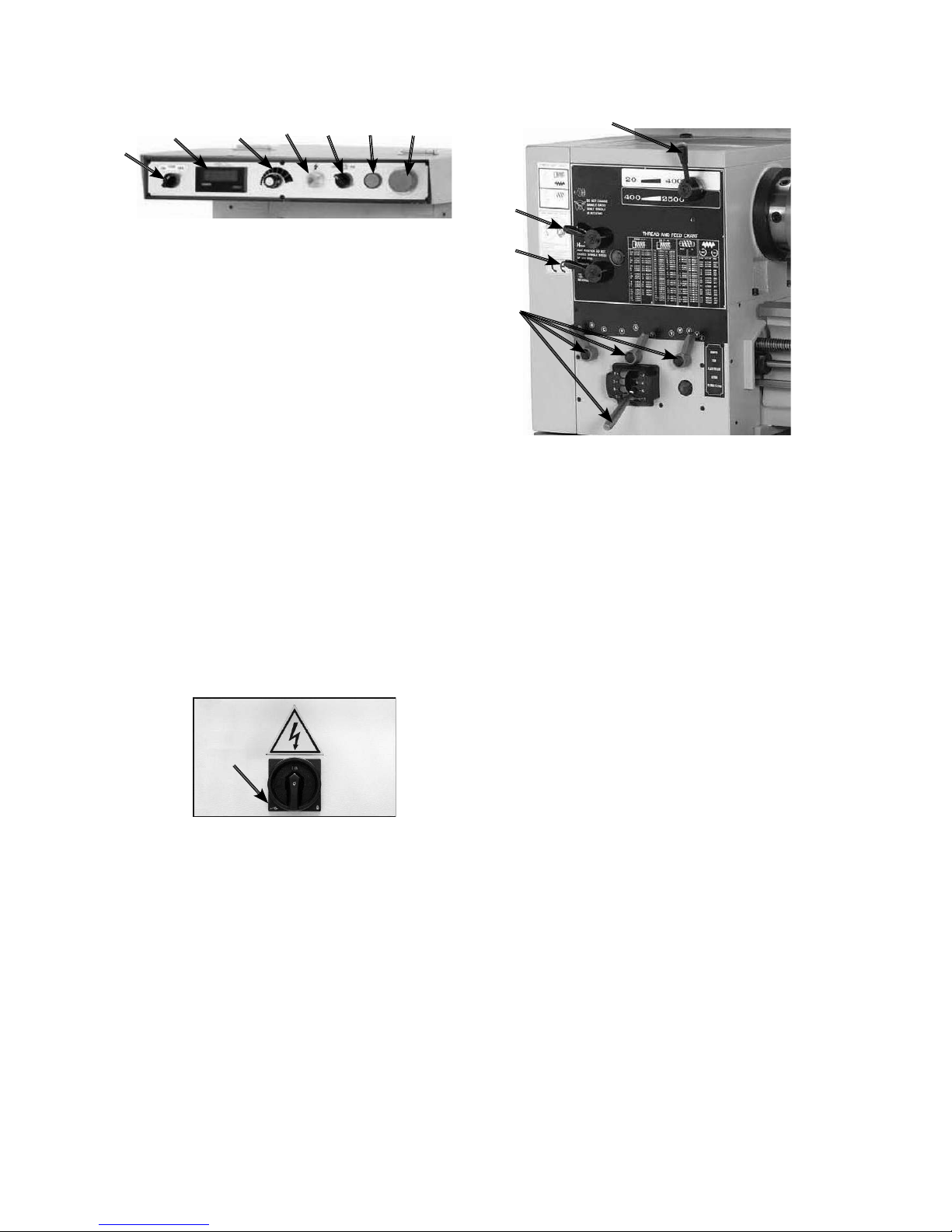
9. Spindle Range Lever : Shifts the headstock into
low or high range for spindle speeds between 20-
400 RPM or 400-2500 RPM.
10. Gearbox Range Lever : This lever puts the
gearbox in high or low range and has no effect
on spindle RPM.
11. Feed Direction Lever : This lever changes
the direction that the gearbox is turning at, and
as a result the leadscrew and feed rod change
direction.
12. Gearbox Levers : Moves the gearbox gears into
particular ratios, which then turn the leadscrew
and feed rod for threading and power feed
operations.
-6-
1. CSS ON / OFF Switch : Turns the constant
surface speed feature ON or OFF.
2. Tachometer Display : Indicates what RPM the
spindle is currently rotating at.
3. Spindle Speed Dial : Changes the spindle speed
to user-defined levels.
4. Power Light : Illuminates when lathe is receiving
power.
5. Cutting Fluid Pump Switch : Turns cutting fluid
delivery ON / OFF.
6. Jog Button : Turns the spindle motor ON while
being pressed and held.
7. Emergency Stop Button : Stops all machine
functions. Twist clockwise to reset.
8. Main Power Switch : Located at the rear of the
lathe on the electrical box cover, this switch turns
power ON / OFF to the lathe so lathe operations
can begin.
Headstock ControlsControl Panel
1234567
Figure 2. Control Panel.
8
Figure 3. Main Power Switch.
9
10
11
12
Figure 4. Headstock Controls.
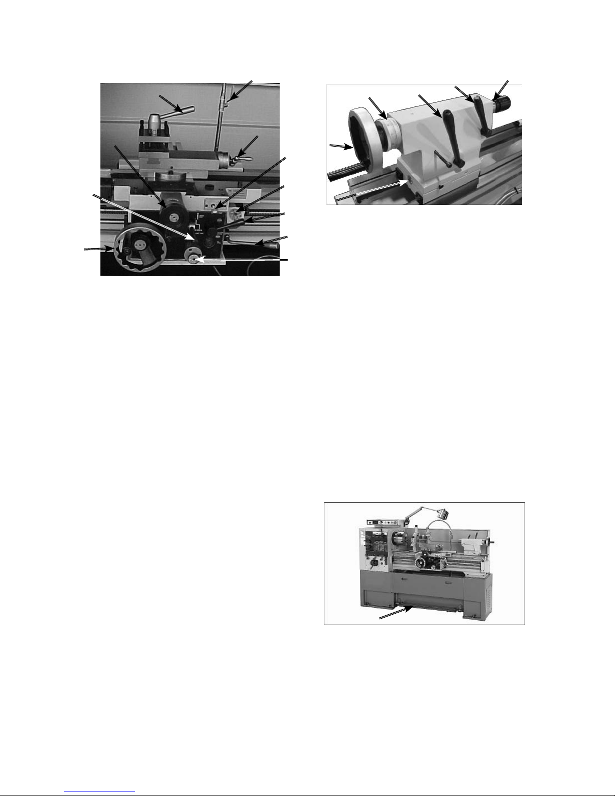
1. Graduated scale : Indicates quill movement in
increments of 0.001" or 0.02mm.
2. Tailstock Lock Lever : Secures the tailstock in
place along the bedway.
3. Quill Lock : Locks the quill in position.
4. Quill : Moves toward and away from the spindle
and holds centers and tooling.
5. Quill Handwheel : Moves the quill toward or
away from the spindle.
6. Offset Scale : Indicates the distance of tailstock
offset from the spindle center line.
7. Tailstock Offset Screw : Adjusts and secures
the tailstock offset (1 of 2).
-7-
1. 4-Position Tool Post Lever : Used for locking
the rotary tool post in four possible detents.
2. Cutting Fluid Flow Control Lever : Used to vary
the flow of cutting fluid out of the nozzle.
3. Compound Hand Crank : Used to position the
compound along the compound slide.
4. Manual Carriage Oil Pump : Draws oil from the
apron case and lubricates the carriage and ways
through various oil ports.
5. Cross Slide Handwheel : Positions the cross
slide in or out.
6. Feed Control Lever : Engages and disengages
the cross feed and longitudinal feed gearing.
7. Longitudinal Carriage Handwheel : Allows for
manual movement of the carriage from left to
right along the bed.
8. Thread Dial : Indicates when to engage the half
nut during threading operations.
9. Halfnut Lever : Engages and disengages the
apron with the leadscrew for threading operations.
10. Spindle ON / OFF Lever : Used to start and stop
the lathe during normal operation.
11. Feed Direction Lever : This lever changes
the direction that the gearbox is turning at, and
as a result the leadscrew and feed rod change
direction.
Tailstock ControlsCarriage Controls
Figure 7. Foot Brake.
Figure 5. Carriage Controls.
1
3
4
5
6
7
8
9
10
11
2
Figure 6. Tailstock Controls.
1
5
6
234
Foot Brake
This lathe is equipped with a foot brake (Figure 6) to
quickly stop the spindle. Pushing the foot brake while
the spindle is ON cuts power to the motor and stops
the spindle. Once stopped, the spindle lever MUST
be returned to the neutral position before the spindle
can be restarted.
-8-
Physical Environment
The physical environment where your machine is
operated is important for safe operation and longevity
of parts. For best results, operate this machine in a
dry environment that is free from excessive moisture,
hazardous or flammable chemicals, airborne
abrasives, or extreme conditions. Extreme conditions
for this type of machinery are generally those where
the ambient temperature is outside the range of 9°
~ 72ºC(41° ~ 104ºF); the relative humidity is outside
the range of 20–95% (non-condensing); or the
environment is subject to vibration, shocks, or bumps.
Electrical Installation
Place this machine near an existing power source.
Make sure all power cords are protected from traffic,
material handling, moisture, chemicals, or other
hazards. Make sure to leave access to a means of
disconnecting the power source or engaging a lockout
/ tagout device.
Lighting
Lighting around the machine must be adequate
enough that operations can be performed safely.
Shadows, glare, or strobe effects that may distract or
impede the operator must be eliminated.
Weight Load
Make sure that the surface upon which the machine is
placed will bear the weight of the machine, additional
equipment that may be installed on the machine, and
the heaviest workpiece that will be used. Additionally,
consider the weight of the operator and any dynamic
loading that may occur when operating the machine.
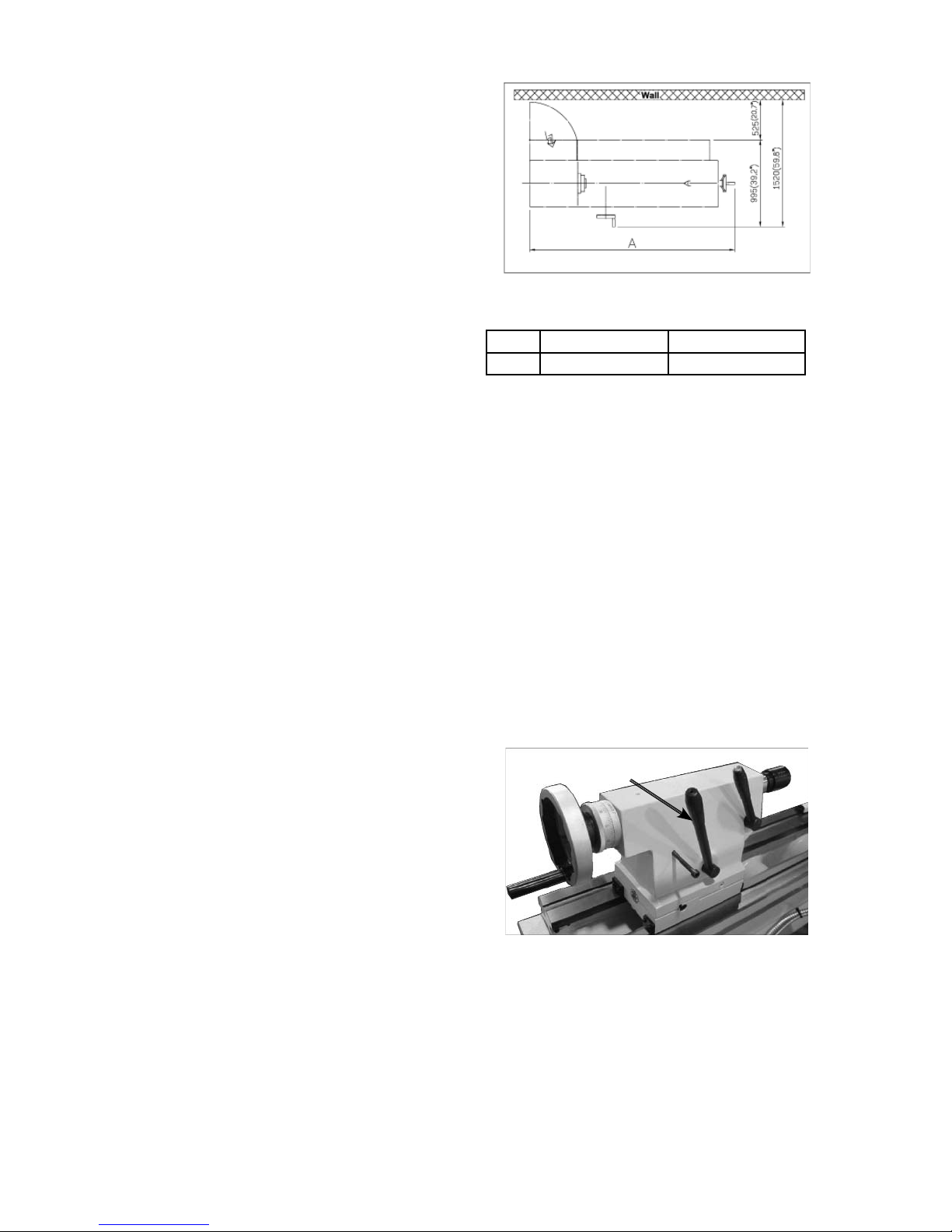
Space Allocation
Consider the largest size of workpiece that will be
processed through this machine and provide enough
space around the machine for adequate operator
material handling or the installation of auxiliary
equipment. With permanent installations, leave
enough space around the machine to open or remove
doors/covers as required by the maintenance and
service described in this manual.
Model 1440 / 1640 1460 / 1660
A 2300mm ( 90.6” ) 2810mm ( 110.6” )
Lifting & Moving
This lathe is an extremely heavy machine. Serious
personal injury or death may occur if safe lifting and
moving methods are not followed. Get assistance
from a professional rigger if you are unsure about
your abilities or maximum load ratings of your lifting
equipment.
To lift and move your lathe :
1. Prepare the permanent location for the lathe.
2. Remove the shipping crate top and sides, then
remove the small components from the shipping
pallet.
3. To balance the lifting load, loosen the tailstock
lock lever ( Figure 9 ), move the tailstock to the
end of the bedway, then lock it in place.
Section 2 : Setup
Tailstock Lock Lever
Figure 9. Tailstock lock lever.
Figure 8. Space required for full range of
movement.
4. To further balance the load, loosen the carriage
lock bolt, disengage the half nut lever, put the
feed control lever in neutral, then use the carriage
handwheel to move the carriage next to the
tailstock. ( Figure 10 )

-9-
7. Moving the machine with a forklift.
a. Make sure that the minimum forklift capacity
is more than 2 tons for security.
b. Forklift work should be cooperatively done
by two persons, that is an operator and
watchman, not to damage projecting on the
machine perimeter.
c. To put the fork, use the fork inserting the
plinth mid-lift.
d. Keep the machine’s balance of gravity at the
center of the forks.
5. Locking the carriage lock bolt and tailstock lock
lever.
6. Lifting the machine with crane.
a. Make sure that minimum crane capacity is
more than 2 tons for security.
b. Only an authorized crane operator should use
the lift machine.
c. Crane work should be cooperatively done
by two persons, that is, an operator and a
watchman, not to damage projecting on the
machine perimeter.
d. To put in the jig with wire set inserting to bed
way.
e. Make sure that two hexagon nuts is fixed.
f. Keep the machine’s center of gravity at the
center of the crane.
Figure 11. Lifting the machine with crane.
Figure 12. Moving the machine with a forklift.
Leveling
This lathe must be placed on the included leveling
studs and cast-iron feet. Complete support at each
of the six leveling stud locations is mandatory. The
bed cannot be twisted or bent, and the ways must
be perfectly level with the floor. If a misalignment
condition arises, adjust the leveling studs, or shim the
cast iron feet where they touch the floor until the bed
and ways are in alignment.
Figure 13. Leveling pads and screws.
Figure 10. Carriage controls set for moving
the carriage.
Carriage
Handwheel
Half Nut Lever
Feed Control
Lever
Lock Bolt
-10-
6. Move the headstock range lever ( Figure 16 ) to
the left so the headstock is in low range ( 20-400
RPM ).
Test Run
After all preparation steps have been completed, the
machine and its safety features must be tested to
ensure correct operation. If you discover a problem
with the operation of the machine or its safety
components, shut the machine down, disconnect it
from power, and do not operate it further until you
have resolved the problem.
To test run the lathe:
1. Disconnect the lathe from POWER !
2. Make sure that the headstock oil tank, gearbox,
apron, and lead screw reservoir oil levels are full.
3. Make sure that the chuck and jaws are secure.
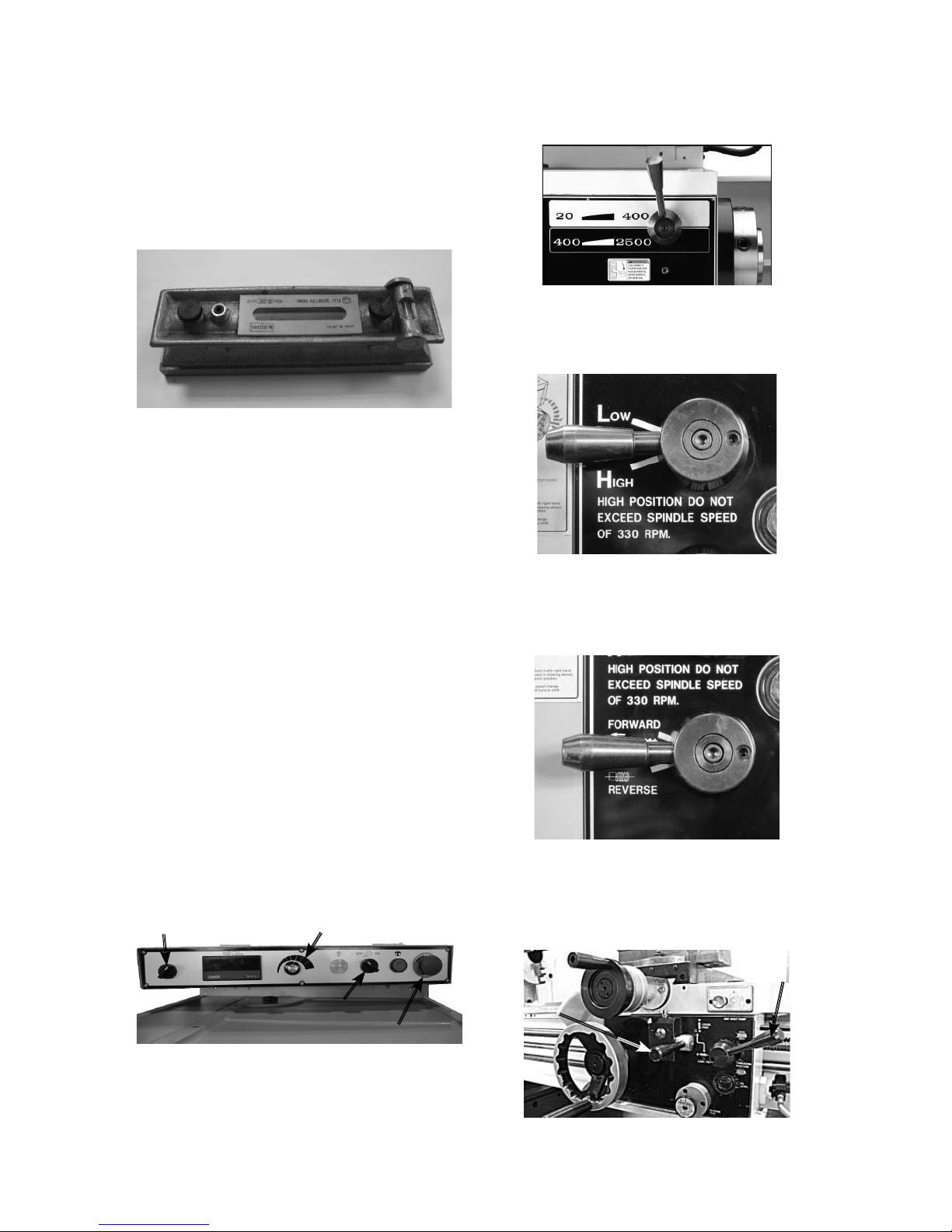
4. Turn the pump switch to the OFF position, fill the
cutting fluid reservoir, and point the fluid nozzle
into the chip pan.
5. Turn the CSS ON / OFF switch to ON, turn the
spindle speed dial ( Figure 13 ) to its minimum
speed, and make sure the cross slide is backed
out to avoid possibility of a high-speed start.
Figure 15. Control panel.
CSS ON / OFF Switch Spindle Speed Dial
Pump Switch
Emergency Stop Switch
Figure 16. Headstock range lever.
Figure 17. Gearbox range lever.
Figure 18. Feed forward / reverse lever.
To level the machine, use a precision level to make
sure the bedways are level from side-to-side and
from front-to-back.
Leveling machinery helps precision components,
such as bedways, remain straight and flat during the
lifespan of the machine. Components on an unleveled
machine may slowly twist due to the dynamic loads
placed on the machine during operation.
Figure 14. Example of a precision level.
Figure 19. Apron disengaged.
Neutral
Half nut Lever
Disengaged
7. Move the Gearbox range lever to neutral as
shown in Figure 17.
8. Move the feed direction forward / reverse lever to
neutral as shown in Figure 18.
9. Disengage the half nut lever, put the feed control
lever in neutral, and make sure the carriage lock
bolt is loose as shown in Figure 19.

-11-
10. Using a 10mm hex wrench, loosen the carriage
lock ( Figure 20 ) so the carriage is free to slide.
Figure 20. Carriage lock.
Figure 21. Spindle ON / OFF lever.
Figure 22. Main Power Switch in ON position.
Figure 23. Oil pump sight glass.
14. Make sure that all bystanders are out of the way,
tools are cleared away, and the chuck key is
removed from the chuck.
15. Move the spindle ON/OFF lever down and the
chuck will rotate.
16. Observe and listen for any abnormal noises or
vibration. The lathe should run smoothly with little
or no vibration or rubbing noises.
17. Push the foot brake, and the lathe should come
to a quick stop.
18. Open the lathe headstock side cover
approximately 25mm so the door safety limit
switch opens and disables the lathe from starting
19. Attempt to start the lathe. Should the lathe
start, the safety limit switch is faulty and needs
replacement.
20. Close the door and start the lathe again, and
push the EMERGENCY STOP switch and the
lathe should stop.
21. Turn the cutting fluid pump on, and fluid should
flow from the nozzle.
22. The test run is now finished. Shut the lathe down
and begin the Spindle Break-In procedure.
11. Move the spindle ON / OFF lever to the OFF
position as shown in Figure 21.
12. Connect the lathe to power, and at the rear of the
headstock, turn the master power switch to the
ON position ( Figure 22 ).
13. Rotate the red EMERGENCY stop switch knob
clockwise until it pops out and the pump will turn
on. Observe the oil pump tube sight glass ( Figure
23 ). When oil flows out of the tube and against
the sight glass, you can start the lathe.
Spindle Break-in
It is essential to closely follow the proper break-
in procedures to ensure trouble-free performance.
Complete this process once you have familiarized
yourself with all instructions in this manual and
completed the test run.
To break-in the spindle :
1. Complete the Test Run procedure.
2. Turn the CSS ON / OFF dial to OFF and the
spindle speed dial to the minimum speed.
3. Move the gearbox range lever ( Figure 24 ) to low
range.
Figure 24. Gearbox range laver.

-12-
4. Move the headstock range lever to low range.
5. Move the feed direction forward / reverse lever (
Figure 25 ) to FORWARD.
7. Turn the lathe ON, and let it run for ten minutes in
each speed of 20, 200, and 400 RPM, using the
dial to adjust the speed.
8. After completing Step 7, stop the lathe and move
the gearbox range lever to neutral, and move the
headstock range lever to high.
9. Turn the lathe ON and let it run at for ten minutes
in each speed of 400, 1000, and 2500 RPM.
10. After completing Step 9, reduce the spindle
speed to 400 RPM and let the lathe run for a
final 15 minutes to allow the machine to cool and
circulate the oil.
11. Shut the lathe down, replace the headstock and
gearbox oil, and re-tension the V-belts.
Figure 26. Power feed and half nut levers
disengaged.
Half nut Lever Disengaged
Nuetral
Figure 25. Feed forward / reverse laver.
6. Disengage the half nut and the power feed levers
shown in Figure 26.
-13-
CSS System
This lathe is equipped with a CSS (Constant Surface
Speed) system (Figure 27) that gives consistent
finishes between surfaces with different diameters.
To install a chuck :
1. Disconnect lathe from POWER !
2. Place a piece of plywood across the lathe ways
and position it just under the chuck.
3. Place the chuck on the cradle.
4. Make sure the chuck taper and spindle taper
mating surfaces are perfectly clean.
5. Inspect and make sure that all camlock studs are
undamaged, are clean and lightly oiled, and that
the camlock stud cap screws are in place and
snug.
6. If equipped, align the chuck-to-spindle timing
marks ( Figure 29 ), and slide the chuck onto the
spindle.
Section 3 : Operation
Figure 27. CSS System.
Spindle RPM Readout
CSS Switch Spindle Speed dial
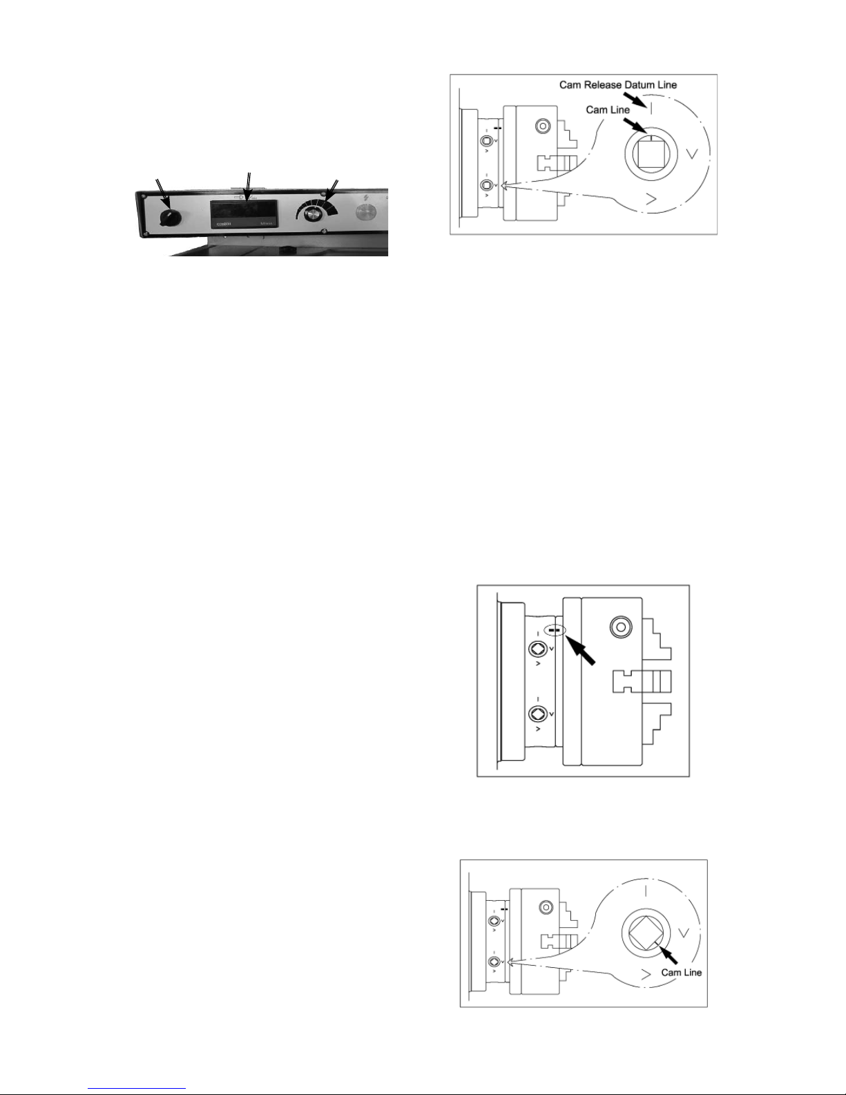
Figure 28. Camlock loosened with the
cam line aligned with the datum line.
Figure 29. Chuck timing marks aligned.
Figure 30. Cam and lines.
If the CSSSS switch is in the ON position, the spindle
speed automatically changes with the position of the
cross slide. For example, during facing operations, as
the tool bit moves toward the center of the workpiece,
the spindle speed increases to maintain a constant
surface speed during cutting as diameter decreases.
As a result of this automatic spindle speed control,
surface finishes are consistent, tooling lasts longer,
and fewer workpieces will be lost from mistakes.
Another benefit derived from the CSSSS feature
is that from reduced machine shutdown and less
lever shifting cycles, shorter machining time will be
achieved which can mean increased productivity.
Note: When the CSSSS switch is in the ON position,
the spindle RPRPM can be adjusted with the spindle
speed dial.
When the CSSSS switch is in the OFF position, the
cross slide position has no effect on spindle speed.
The spindle speed is only adjusted with the spindle
speed dial.
Chuck
This lathe is shipped with the 3-jaw chuck installed.
This is a scroll-type chuck, meaning that all three
jaws move in unison when adjusted.
The included 4-jaw chuck features independent jaws,
which are used for square or unevenly-shaped stock.
If neither chuck can hold your workpiece, the cast-iron
faceplate has slots for T-bolts that hold standard or
custom clamping hardware. With the correct clamping
hardware, this faceplate will hold non-cylindrical parts
such as castings.
The chucks and faceplate have a D-6 camlock mount.
A chuck key is used to turn the locking cams ( Figure
28 ) to secure / release the chuck / faceplate.
7. Turn a camlock with the chuck key until the cam
line falls between the "V" marks shown in Figure
30.

-14-
8. Lock the other cams in a crisscross or star
pattern so the chuck is drawn up evenly on all
sides without any chance of misalignment.
9. Remove the chuck key.
To remove a chuck :
1. Disconnect lathe from POWER !
2. Place a piece of plywood across the lathe ways
to protect the ways, or use a support cradle and
position it just under the chuck.
3. Turn a cam with the chuck key until the cam line
aligns with the cam release datum line.
4. Unlock the other cams in the same manner. Make
sure to support the chuck as you align the last
cam.
5. Remove the chuck key.
Installing and Adjusting Camlock
Stud
When fitting a chuck or faceplate with camlock studs,
or when mounting a new chuck or faceplate, it may
be necessary to install or adjust the camlock studs.
In order to properly install or adjust one or more
camlock studs, you must remove a stud locking cap
screw, then thread the camlock stud in or out until the
line on the side of the stud is flush with the top of the
chuck casting.
3-Jaw Chuck
The 3-jaw scroll-type chuck included with this
lathe features hardened steel jaws that center the
workpiece. When the operator opens or closes the
jaws with the chuck key, the jaws move in unison.
There are two sets of jaws included with the 3-jaw
chuck ─inside and outside jaws. Use the correct jaws
for the size and configuration of the workpiece to hold
it firmly and securely on the chuck.
Numbered from 1-3, the jaws must be used in the
matching numbered jaw guides, as shown in Figure
31.
To change the jaw :
1. Disconnect Lathe from POWER !
2. Place a piece of wood over the ways to protect
them from potential damage.
3. Insert the chuck key and turn it counterclockwise
to back the jaws out and remove them.
4. Clean the jaw mating surfaces and apply a thin
film of white lithium grease to the mating surfaces.
5. Set the previously mounted jaws aside in a safe
place free of moisture and abrasives.
6. Rotate the chuck key clockwise until you see
the tip of the scroll gear lead thread just begin to
Insert jaw #1 into jaw guide #1 and hold the jaw
against the scroll gear lead thread.
7. Rotate the chuck key clockwise one turn to
engage the tip of the scroll gear lead thread into
the jaw.
Lead Thread
Figure 32. Inserting jaw.
Jaw Guide #1
Jaw Numbers
Figure 31. Jaw guides and jaw numbers.
8. Pull on the jaw—now it should be locked into the
jaw guide.
9. Repeat the Steps 6–8 on the remaining jaws.
To mount a workpiece in the 3-jaw chuck :
1. Disconnect Lathe from POWER !
2. Place a chuck cradle or plywood on the bedway
below the chuck to protect it.
3. Use the chuck key to move the jaws and mount
the workpiece to the chuck, similar to one of the
methods shown in Figure 33. Make sure the
workpiece is mounted firmly on the chuck.

-15-
Figure 33. Examples of workpiece
mounted in the 3-jaw chuck.
4. Rotate the chuck by hand to make sure the
workpiece makes even contact with all three jaws
and is centered.
4-Jaw Chuck
The 4-jaw chuck features independently adjustable
hardened steel jaws to hold non-cylindrical or off-
center workpieces. Each jaw can be removed from
the chuck body and reversed for a wide range of work
holding versatility.
To mount a workpiece on the 4-jaw chuck :
1. Disconnect Lathe from POWER !
2. Place a chuck cradle or plywood on the bedway
below the chuck to protect it.
3. Use the chuck key to open each jaw so the
workpiece will lay flat against the chuck face or
jaw steps.
4. With help from another person or a supporting
device, mount the workpiece centered on the
chuck, then turn each jaw until it makes contact
with the workpiece.
5. Tighten each jaw in small increments. After you
have adjusted the first jaw, continue tightening in
an opposing sequence.
6. After the workpiece is held in place by the jaws,
turn the chuck by hand and pay attention to the
workpiece alignment.
Tailstock
The tailstock on your lathe can be used to support
workpieces with the use of a live or dead center.
Figure 34. Tailstock and quill lock handles in
locked position.
Quill Handwheel
Tailstock Lock Lever
Tailstock Lock Lever
To move the tailstock :
1. Pull back on the lock lever.
2. Slide the tailstock to the desired position.
3. Push the tailstock lock lever forward to lock the
tailstock to the lathe bed.
To use the tailstock quill :
1. With the tailstock locked to the bed, release the
quill lock lever.
2. Turn the quill feed handwheel clockwise to
feed/move the quill towards the spindle, or turn
counterclockwise to move the quill away from the
spindle.
3. Push the quill lock lever forward to lock the quill
in place.
To install tooling in the tailstock :
1. With the tailstock locked, unlock the quill lock
lever.
2. Turn the quill handwheel CW to extend quill about
25mm out of the casting.
3. Insert a tapered drill arbor or a tapered drill bit
into the quill until the taper is firmly seated and
the tang is locked to the quill slot.
4. Turn the quill handwheel CW to feed the drill bit
into the rotating workpiece.
5. To remove the tooling from the tailstock, turn the
quill handwheel CCW until the tooling is pushed
out of the taper.
To offset the tailstock :
1. Lock the tailstock in position, and adjust the left
and right jack screws until the scale ( Figure 35 )
indicates the offset you want. See Figure 36 for
adjustment direction.
It can also be used to drill or bore holes in the center
of a part or cut shallow tapers by using the offset
adjustment.

-16-
Figure 35. Tailstock offset adjustments.
Scale
Left Side
Jack Screw
Centers
Dead Centers
The dead center achieves more accurate results than
a live center, but it requires low spindle speeds and
a small amount of oil to reduce friction heat that may
damage the workpiece.
Use the HSS dead center in the spindle, where the
workpiece does not rotate on the tip and does not
generate friction.
Use the carbide-tipped dead center in the tailstock
where the workpiece will rotate against it and
generate friction. The carbide-tipped dead center can
better withstand the effects of friction; however, the tip
of the center must be lubricated to avoid premature
wear and maximize smooth operation. Also, using
low spindle speeds will also reduce the heat and wear
from friction.
Live Centers
A live center has bearings that allow the center tip and
the workpiece to rotate together, and can be installed
in the spindle and the tailstock quill for higher speeds,
but with a slight bit of accuracy loss.
Mounting Dead Center in Spindle
1. Disconnect Lathe from POWER !
2. Thoroughly clean and dry the tapered mating
surfaces of the spindle bore, tapered sleeve, and
the center.
3. Insert the center into the sleeve, then insert the
sleeve into the spindle bore through the chuck or
faceplate.
Removing Center from Spindle
To remove the sleeve and center from the spindle,
insert a piece of round bar stock or similar tool through
the outboard end (on the left side of the headstock),
then tap the sleeve loose.
Mounting Center in Tailstock
Either a dead center or live center can be mounted
in the tailstock. Mounting instructions are the same
for both.
Figure 36. Jack screw adjustment verses
tailstock movement.
Figure 37. Example of using a dead
center installed in the tailstock.
2. When the offset is achieved, snug the jack screws
so the tailstock position is locked.
To mount a center in the tailstock :
1. Disconnect Lathe from POWER !
2. Thoroughly clean and dry the tapered mating
surfaces of the tailstock quill bore and the carbide-
tipped dead center.
3. Use the tailstock quill handwheel to feed the quill
out from the casting about 25mm.
4. Insert the center into the tailstock quill.
5. Seat the center firmly into the quill during
workpiece installation by rotating the quill
handwheel clockwise to apply pressure.
Removing Center from Tailstock
To remove the center from the quill, hold onto it with a
rag in one hand, then rotate the tailstock handwheel
counterclockwise to draw the quill back into the
casting until the center released.

-17-
Steady Rest
The steady rest supports long shafts and can be
mounted anywhere along the length of the bed.
To install and use the steady rest :
1. Disconnect Lathe from POWER !
2. Thoroughly clean the machined base of the
steady rest, then place it on the lathe bedways so
the triangular notch fits over the bedway prism.
3. Position the steady rest where required to
properly support the workpiece, then tighten the
hex nut shown in Figure 38 to secure it in place.
Figure 38. Steady rest components.
Finger Adjustment Knob
Wing Bolt
Finger Roller
Hex. Nut
Lock Knob
Figure 39. Workpiece mounted in
the steady rest.
Figure 40. Follow rest attachment.
CAP Screws
4. Loosen the lock knob and open the steady rest so
the workpiece can rest on the bottom two finger
rollers, as shown in Figure 39.
Follow Rest
The follow rest mounts to the saddle with two cap
screws (Figure 40). It is used on long, slender parts
to prevent workpiece flexing from the pressure of the
cutting tool during operation.
Adjust the sliding finger rollers on the follow rest in the
same manner as those on the steady rest.
Compound Slide
The compound slide handwheel has an indirect-read
graduated scale. This means that the distance shown
on the scale represents the actual distance the tool
moves, which of course, will remove twice as much
material from the diameter of the workpiece. The
base of the compound slide has another graduated
scale used for setting the tool to a specific angle.
To set the compound slide at a certain angle :
1. Loosen the two hex nuts at the base of the
compound slide (1 of 2 shown in Figure 41).
Figure 41. Compound slide set at an angle.
Lock Knob
Compound slide
5. Close the steady rest so that the workpiece is
inside the finger rollers, then tighten the lock
knob.
6. Loosen the three wing bolts so the finger roller
positions can be adjusted.
7. Use the finger adjustment knobs to just touch
the finger rollers against the workpiece without
causing workpiece deflection.
8. Tighten the three wing bolts.
2. Rotate the compound to the desired angle, as
indicated by the scale at the base, then retighten
the two hex nuts.

-18-
Figure 42. 4-way tool post.
Tool Post Bolts
Cutting Tool
Figure 43. Cutting tool aligned with
workpiece center.
4-Way Tool Post
The four-way tool post is mounted on top of the
compound slide, and allows a maximum of four tools
to be loaded simultaneously.
The four-way tool post allows for quick indexing to
different tools. This is accomplished by loosening
the top handle, rotating the tool post to the desired
position, then re-tightening the handle to lock the tool
into position.
To load the tool post :
1. Choose the desired cutting tool.
2. Loosen the tool post bolts so that the cutting tool
can fit underneath them.
3. Firmly secure the cutting tool with at least two tool
post bolts, as shown in Figure 42.
Aligning Cutting Tool with Tailstock
Center
For most operations, the cutting tool tip should be
aligned with the spindle center line, as illustrated in
Figure 43.
There are a number of ways to check and align the
cutting tool to the spindle center line. Below are two
common methods :
• Align the tip of the cutting tool with a center
installed in the tailstock. For this to work, the
tailstock must be aligned to the spindle center
line.
• Make a facing cut on a piece of round bar stock.
If the tool is above/below the spindle center line,
a nub will be left in the center of the workpiece.
Adjust the height of the workpiece, then repeat
the facing cut to check the adjustment. Repeat
as necessary until the center of the workpiece is
smoothly faced.
To align the cutting tool with the tailstock center :
1. Mount the cutting tool in the tool post, then turn
the tool post so the tooling faces the tailstock.
2. Install a center in the tailstock, and position the
center tip near the tip of the cutting tool.
3. Lock the tailstock and quill in place.
4. Adjust the height of the cutting tool with a steel
shim, so the tip just touches the end of the
tailstock center.
Apron Stop
Use the adjustable apron stop collar to set the location
where the carriage will be disengaged by the feedrod
friction clutch.
When the adjustable apron stop contacts the stop
collar during a longitudinal feeding operation, the
clutch disengages the feedrod from the apron and the
carriage movement stops.
Figure 44. Apron stop and collar.
Stop Collar
Apron
Apron Stop

-19-
Longitudinal Handwheel
The longitudinal handwheel moves the carriage left or
right along the bed. Use this control when setting up
the machine for facing or turning.
Cross Slide Handwheel
The cross slide handwheel moves the top slide toward
and away from the work. Turning the dial clockwise
moves the slide toward the workpiece. Adjust the
graduated scale by holding the handwheel with one
hand and turning the dial with the other.
Compound Slide Handwheel
The compound slide handwheel controls the position
of the cutting tool relative to the workpiece. The
compound is adjustable for any angle within its range.
The combo inch/metric graduated scale is engraved
into a rotatable barrel. Angle adjustment is secured
by cap screws on the base of the compound.
Spindle Speed
Using the correct spindle speed is important for safe
and satisfactory results, as well as maximizing tool
life.
To set the spindle speed for your operation, you
will need to :
1. Determine the best spindle speed for the cutting
task.
2. Configure the lathe controls to produce the
required spindle speed.
Figure 45. Carriage Controls.
Longitudinal
Handwheel
Cross Slide
Handwheel
Compound Slide
Handwheel
Determining Spindle Speed
Many variables affect the optimum spindle speed
to use for any given operations, but the two most
important are the recommended cutting speed for the
workpiece material and the diameter of the workpiece,
as noted in the formula :
RPM = D
CSx4
RPM = Spindle speed, revolution per minute.
CS = Cutting speed in surface feet per minute ( SFM )
D = Diameter of workpiece
EXAMPLE :
If the cutting speed is 40 for a certain alloy steel and
the workpiece is 2 inches in diameter, find the rpm as
follows :
RPM = = 80
After calculating the RPM, use the nearest or next
lower speed on the lathe and set the spindle speed.
Cutting speed, typically defined in feet per minute
(FPM), is the speed at which the edge of a tool moves
across the material surface.
A recommended cutting speed is an ideal speed
for cutting a type of material in order to produce the
desired finish and optimize tool life.
The books Machinery’s Handbook or Machine Shop
Practice, and some internet sites, provide excellent
recommendations for which cutting speeds to use
when calculating the spindle speed.
These sources also provide a wealth of additional
information about the variables that affect cutting
speed and they are a good educational resource.
Also, there are a large number of easy-to-use spindle
speed calculators that can be found on the internet.
All of these sources will help you take into account all
the applicable variables in order to determine the best
spindle speed for the operation.
Setting Spindle Speed
1. Make sure the spindle is turned OFF and it has
come to a complete stop.
2. Use the chart in Figure 46 to determine the
available spindle speed range closest to your
calculated spindle speed.
SPEEDS
LEVER RPM
LOW 20 – 40
HIGH 400 - 2500
Figure 46. Spindle speed range chart.
Manual Feed
You can manually move the cutting tool around
the lathe for facing or turning operations using the
handwheels shown in Figure 45 and described below.
-20-
3. Adjust the spindle speed range lever to the range
that covers your calculated spindle speed.
4. Turn the spindle ON and slowly turn the variable
speed dial to carefully adjust the spindle speed to
your calculated spindle speed.
Power Feed
On this machine, both the carriage and cross slide
have power feed capability. The rate that these
components move (feed rate) is controlled by how the
levers are configured on the gearbox.
Feed rate and spindle speed must be considered
together. The sources you use to determine the
optimum spindle speed for an operation will also
provide the optimal feed rate to use with that spindle
speed.
Often, the experienced machinist will use the feeds
and speeds given in their reference charts or web
calculators as a starting point, then make minor
adjustments to the feed rate (and sometimes spindle
speed) to achieve the best results.
The carriage can alternately be driven by the
leadscrew for threading operations. However, this
section covers using the power feed option for
the carriage and cross slide components for non-
threading operations.
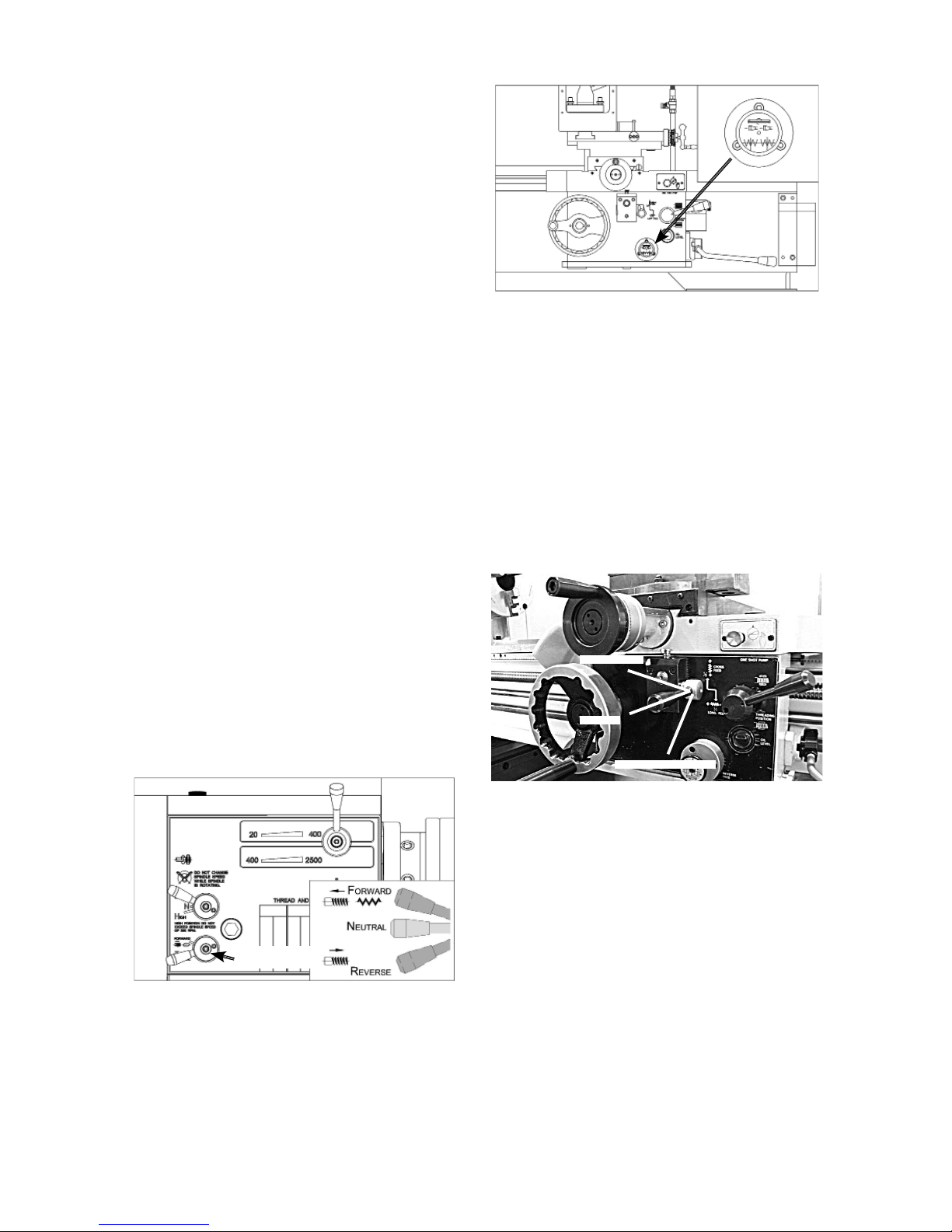
Power Feed Controls
The feed direction lever controls direction of the
carriage. The quick change feed direction knob
reverses the feed direction of the carriage while the
lathe is running.
Figure 49. Feed control lever positions.
Cross Feed
Neutral
Longitudinal Feed
To engage the power feed :
1. Make sure the spindle is OFF and has come to a
complete stop.
2. Use the feed direction lever to select the direction
that the feed rod will rotate.
3. Use the feed control lever on the front of the apron
to engage power feed for either the carriage or
the cross slide (see Figure 49). To engage the
carriage, push the lever to the left and down. To
engage the cross slide, push the lever to the right
and up.
Feed Direction
Lever
Figure 47. Feed Direction Lever.
Figure 48. Quick change feed direction knob.
To use the quick change feed direction knob :
1. While the lathe is running, place the feed control
lever in neutral.
2. Push or pull the quick change feed direction knob
to change the direction of the feed rod.
3. Re-engage the feed direction lever. The feed
rod rotation will now be reversed, causing the
engaged carriage or cross slide to move in the
opposite direction.
Table of contents


