VEVOR WM210V-L User manual

Technical Support and E-Warranty Certificate www.vevor.com/support
LATHE INSTRUCTION MANUAL
MODEL:WM210V-L
We continue to be committed to provide you tools with competitive price.
"Save Half", "Half Price" or any other similar expressions used by us only represents an
estimate of savings you might benefit from buying certain tools with us compared to the major
top brands and doses not necessarily mean to cover all categories of tools offered by us. You
are kindly reminded to verify carefully when you are placing an order with us if you are
actually saving half in comparison with the top major brands.


- 1 -
MODEL:WM210V-L
Have product questions? Need technical support? Please feel free to
contact us:
CustomerService@vevor.com
NEED HELP? CONTACT US!
This is the original instruction, please read all manual instructions
carefully before operating. VEVOR reserves a clear interpretation of our
user manual. The appearance of the product shall be subject to the
product you received. Please forgive us that we won't inform you again if
there are any technology or software updates on our product.
LATHE

- 2 -
MATTERS NEEDING ATTENTION
The information contained in this handbook is intended as a guide to the
operation of these machines and does not form part of any contract.The
data it contains has been obtained from the machine manufacturer and
from other sources. We strive to ensure the accuracy of this information
and try to verify each item and each data, but we cannot guarantee the full
accuracy of the information, which means that the equipment supply may
differ in detail from the description of the instructions. Furthermore,
development of the machine may mean that the equipment supplied may
differ in detail from the descriptions herein. The responsibility therefore lies
with the user to satisfy himself that the equipment or process described is
suitable for the purpose intended.
QUALITY ASSURANCE
We will make every effort to ensure the quality of our products, and we
promise to consumers that we will guarantee our products for one year,
except for machine damage caused by improper operation of customers,
and accidents resulting therefrom, or abnormal wear and damage caused
by lack of maintenance.
In order to fulfill the warranty commitment, the product or part with quality
problems, please return to us for verification, postage prepaid. Goods sent
back should be accompanied by a note of the date of purchase and a
written explanation of the quality of the product. After our inspection and
confirmation, we will repair or replace their products, or refund the payment;
If we fail to provide repair or replacement in a timely manner, we shall bear
the costs arising from the repair or replacement of the products; If the
damage is not due to the quality of the product, but due to the user's
improper operation or other reasons, the cost shall be borne by the
customer .

- 3 -
Our company reserves the right to make changes to this specification and
product specifications. We will make continuous efforts to improve the
quality of our products.
All rights reserved. Reproduction or reproduction is not allowed without
permission.
SAFETY WARNING
Symbol Symbol Description
Warning - To reduce the risk of injury, user must read instructions
manual carefully.
This symbol, placed before a safety comment, indicates a kind of
precaution, warning, or danger. Ignoring this warning may lead to an
accident. To reduce the risk of injury, fire, or electrocution, please
always follow the recommendation shown below.
Danger!
Risk of personal injury or environmental damage! Risk of electric
shock! Risk of personal injury by electric shock!
Alternating current
Beware of clamping
Warning- Be sure to wear ear protectors when using this product.
Warning- Be sure to wear eye protectors when using this product.

- 4 -
Do not put your hands into safety guard when machine is working
No entry automatic machinery in operation Authorized personnel only
Do not fill oil during operation
Do not turn during repair
No fatigue operation
The operation is no phone calls
Disposal information:
This product is subject to the provision of European Directive
2012/19/EC. The symbol showing a wheelie bin crossed through
indicates that the product requires separate refuse collection in the
European Union. This applies to the product and all accessories
marked with this symbol. Products marked as such may not be
discarded with normal domestic waste, but must be taken to a
collection point for recycling electrical and electronic devices
WARNING: Read all safety warnings, instructions, illustrations and
specifications provided with this machine. Failure to follow all instructions
listed below may result in electric shock, fire and/or serious injury.
Save all warnings and instructions for future reference.
1.The machine tool should be used by experienced personnel. If you are
not familiar with the operation process of the lathe, do not use the

- 5 -
machine tool at will. Use the instructions before operating.
2.Before starting the machine tool, the safety cover should be in the correct
position.
3.Before starting the machine tool, please check whether the tool rest
wrench and chuck key are removed.
4.Prevent the machine from starting accidentally. Turn off the motor power
before clamping the workpiece or tool.
5.Don't force cut. Cutting according to the set cutting speed, cutting depth
and feed speed.
6.Use the right tools. Use the correct tool or workpiece for machining.
7.Keep the tool sharp and clean to ensure normal and safe operation.
Lubricate and replace accessories regularly.
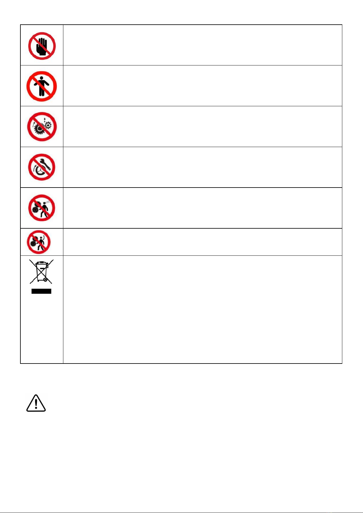
8.Before adjusting or repairing the machine, be sure to disconnect the
power supply.
9. Please check the safety performance of the machine before starting it.
Check the performance of all moving parts. All parts must be installed
correctly. Damaged parts must be repaired promptly.
10. When the machine is running, the operator shall not leave.
11. Keep the working place clean, dirty working environment is easy to lead
to accidents.
12. Do not use the machine in dangerous environment.
Do not work in damp places. Ensure that electrical components are
protected from moisture. Keep good lighting.
13. Children are prohibited from entering the work site, and non-operating
personnel should keep a safe distance from the work area.
14. To keep children out of the work area. The door should be locked when
leaving the workshop.
15. Dress appropriately. Don't wear loose clothing, gloves, ties, rings,
bracelets, jewelry, etc. To be on the safe side, For the sake of safety,
wearing non-slip shoes. If you have long hair, please wear a work hat.
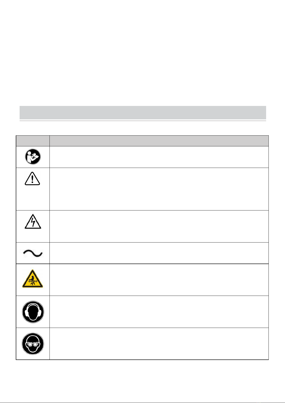
16. Wear protective glasses when operating.
17. Pay attention to where you stand and keep your balance at all times.
18. Do not place your hands near the moving parts of the machine.

- 6 -
19. Do not perform any setting operations while the machine is running.
20. Read and understand all warning signs posted on the machine.
21. This manual is intended only to familiarize customers with the operation
of the machine and is not a training manual.
22. Please obey these warnings or serious injury may result.
23. The machine will produce some harmful chemicals in the work of dust,
sawing, grinding and drilling produced by grinding. To reduce the harm
of these chemicals, please work in a well-ventilated place and wear
safety devices. Such as particulate filter masks.

- 7 -
TECHNICAL PARAMETER
Type number WM210V-L
Capacities
Swing over Bed 210mm
Swing over Cross Side 110mm
Distance Between Centers 735mm
Width of Bed 100mm
Headstock
Hole Through Spindle 38mm
Taper in Spindle Nose MT3
Number of Spindle Speeds Variable
Range of Spindle Speeds 50-2500RPM
Feeding and Threading
Number of Metric Threads 14
Range of Metric Threads 0.3~3mm
Number of 1mperiaI Threads 10
Range of 1mperiaI Threads 10~44T.P.I.
Range of Longitudinal Feed 0.1~0.20mm
Compound and Carriage
Tool Post Type 4
Maximum Compound Slide Travel 55mm
Maximum Cross Slide Travel 75mm
Maximum Carriage Travel 736mm
tail stock
Tail Stock Spindle Travel 60mm
Taper in Tail stock Spindle MT2
Miscellaneous
Main Motor 110V~60Hz/220-240V~50Hz,1Ph
/750W
,
Length, Width and Height 1200×340×360(mm)
Product Weight N.W:79Kg; G.W:90Kg
Package Size 1230*460*450 mm
The general information given in this specification is not binding.

- 8 -
Standard accessories
1
1
1
1
1. Oil Pan
2. Rear Chip Plate
3. Three Jaw Chuck
4. Specification
5. Tool Box
1
Accessories in the tool box (Fig. 1 )
1
1
3
1
1
1
1
5
3
8
Special accessories(Accessories that require additional payment
Dead Center MT5
Dead Center MT2
Tool Post Wrench
Oil Gun
Cross Screwdriver
Fiat Screwdriver
Three Jaw Chuck
Hex Socket Wrenches
Double End Head Wrenches
Pulley Set (30T,33T,35T,50T,52T,40T,60T,66T )
)
Four jaw chuck and back plate
(connecting plate)
Heel rest
Center frame
Back disk
Disjointed disk
Tool rest protection cover
Lead screw protective cover
Turning tool
Drill chuck and connecting rod
Fig. 1

- 9 -
UNPACKING AND CLEANING
1. Finish removing the wooden crate from around the lathe
2. Check all the accessories of the machine tool according to the packing
list.
3. Unbolt the lathe from the shipping crate bottom.
4. Choose a location for the lathe that is dray, has good lighting and has
enough room to be able to service the lathe on all four sides.
5. With adequate lifting equipment, slowly raise the lathe off the shipping
crate bottom. Do not lift by spindle. Make sure lathe is balanced before
moving to sturdy bench or stand.
6. To avoid twisting the bed, the lathe's location must be absolutely flat and
level. Bolt the lathe to the stand (if used). 1f using a bench, through bolt
for best performance.
7. Clean all rust protected surfaces using a mild commercial solvent,
kerosene or diesel fuel. Do not use paint thinner, gasoline or lacquer
thinner. These will damage painted surfaces. Cover all cleaned surfaces
with a light film of 20W machine oil.
8. Remove the end gear cover. Clean all components of the end gear
assembly and coat all gears with heavy, non-slinging grease.
FOUNDATION DRAWING
Fig. 2

- 10 -
General Description
Lathe Bed (Fig. 3)
The lathe bed is made of high-grade iron. By combining high cheeks with
strong cross ribs, a bed of low vibration and rigidity is produced. It
integrates the Headstock and drives the unit, for attaching the carriage and
lead screw. The two precision-ground V - sideways, reinforced by heat
hardening and grinding, are the accurate guide for the carriage and tail
stock. The main motor is mounted to the rear of the left side of the bed.
Fig. 3
Headstock (Fig. 4)
The Headstock is cast from high-grade,low vibration cast iron.It is bolted to
the bed with four screws.The Headstock houses the main spindle with two
precision taper roller bearings and the drive unit.
The main spindle transmits the torque during the turning process.It also
holds the workpieces and clamping devices. (e.g.3-jaw chuck).
Fig. 4

- 11 -
Carriage (Fig. 5)
The carriage is made from high-quality cast iron. The slide parts are
smoothly ground.They fit the V on the bed without play. The lower sliding
parts can be easily and simply adjusted.The cross slide is mounted on the
carriage and moves on a dove-tailed slide.Play in the cross slide may be
adjusted with the gibs.
Move the cross slide with its conveniently positioned Handwheel.
There is a graduated collar on the Handwheel.
A four way tool post is fitted on the top slide and allows four tools to be
clamped.Loosen the center clamp handle to rotate any of the four tools into
position.
Fig. 5

- 12 -
Apron (Fig. 6)
The apron is mounted on the bed. It houses the half nut with an engaging
lever for activating the automatic feed. The half nut gibs can be adjusted
from the outside.
A rack, mounted on the bed, and a pinion operated by Handwheel on the
carriage allows for quick travel of the apron.
Fig. 6
Lead screw (Fig. 7)
The lead screw (A, Fig.7) is mounted on the front of the machine bed. It is
connected to the gear box at the left for automatic feed and is supported by
bearing on both ends. The hex nut(B,Fig.7)on the right end is designed to
take up play on the lead screw.
B
A
Fig.7

- 13 -
tail stock (Fig. 8)
The tail stock slides on a V way and can be clamped at any location. The
tail stock has a heavy-duty spindle with a Morse taper No. 2 socket and a
graduated scale. The spindle can be clamped at any location with a
clamping lever. The spindle is moved with a hand wheel at the end of the
tailstock.
C
Fig.8
Notice:
Fit the securing screw (C, Fig. 8) at the end of the lathe in order to prevent
the tailstock from falling off the lathe bed.
Operating equipment
1. Emergency Button: 0N/0FF Switch (D,Fig. 9)
The machine is switched on and off with ON/OFF button. Depress to stop
all machine functions. To restart, lift the cover and press ON button.
2. Change-over Switch(E,Fig. 9)
After the machine switched on, turn the switch to "F" position for
counter-clockwise spindle rotation(forward). Turn the switch to"R"

- 14 -
position for clockwise spindle rotation(reverse) ."O"position is OFF and the
spindle remains idle.
3. Variable Speed Control Switch (F,Fig. 9)
Turn the switch clockwise to increase the spindle speed. Turn the switch
counter-clockwise to decrease the spindle speed. The possible speed
range is dependent from the position of the drive belt.
E
Fig.9
4﹒Carriage Lock
Turn hex socket cap screw (A, Fig. 10) clockwise and tighten to lock. Turn
counter-clockwise and loosen to unlock.
Caution: carriage lock screw must be UN locked before engaging
automatic feeds or damage to lathe may occur.
A
Fig.10
F
D

- 15 -
5﹒Longitudinal Traverse Hand wheel (B,Fig.11)
Rotate hand wheel clockwise to move the apron assembly toward the tail
stock (right). Rotate the hand wheel counter-clockwise to move the apron
assembly to ward the Headstock(left).
6﹒Cross Traverse Lever (C,Fig. 11)
Clockwise rotation moves the cross slide toward the rear of the machine.
7﹒Half Nut Engage Lever (D,Fig. 11)
Move the lever down to engage. Move the lever up to disengage.
8﹒Compound Rest Traverse Lever (E,Fig. 11)
Rotate clockwise or counter-clockwise to move or position.
9﹒Tool Post Clamping Lever (F,Fig. 11)
Rotate counter-clockwise to loosen and clockwise to tighten. Rotate the
tool post when the lever is unlocked.
F
D
Fig.11
E
C
B

- 16 -
10﹒Tail stock Clamping screw (G,Fig. 12)
Turn hex nut clockwise to lock and counter-clockwise to unlock.
11﹒Tail stock Quill Clamping Lever (H,Fig. 12)
Rotate the lever clockwise to lock the spindle and counter-clockwise to
unlock it.
12﹒Tail stock Quill Traverse Hand wheel (I,Fig. 12)
Rotate clockwise to advance the quill. Rotate counter- clockwise to retract
the quill.
13﹒Tail stock off-set Adjustment (J,Fig. 12)
Three sets screws located on the tails stock base are used to off-set the tail
stock for cutting tapers. Loosen lock screw on tail stock end. Loosen one
side set screw while tightening the other until the amount of off-set is
indicated on scale. Tighten lock screw.
Fig﹒12
H
I
J
G

- 17 -
OPERATION
Replacement of Chuck
The head spindle holding fixture is cylindrical. Loose three set screws and
nuts (A, Fig. 13 only two are shown)on the la the chuck flange to remove
the chuck. Position the new chuck and fix it using the same set screws and
nuts.
Fig. 13
TOOL SET UP
Clamp the turning tool into the tool holder.
The tool must be clamped firmly. When turning, the tool has a tendency to
bend under the cutting force generated during the chip formation.
For best results, tool overhang should be kept to a minimum of 3/8" or
less.
The cutting angle is correct when the cutting edge is inline with the center
axis of the workpiece. The correct height of the tool can be achieved by
comparing the tool point with the point of the center mounted in the tail
stock. If necessary, use steel spacer shims under the tool to get the
required height. (Fig. 14)
A

- 18 -
Fig. 14
Change Speed
1. Unscrew the two fastening screws (B, Fig.15) and remove the
protective cover.
2. Adjust the V-belt(C,Fig.16)corresponding position.
3. Tighten the tension pulley and fasten the nut again.
Fig. 15 Fig. 16
B
C
Table of contents
Other VEVOR Lathe manuals
Popular Lathe manuals by other brands

Jet
Jet Elite E-1236VS Operating instructions and parts manual

Struers
Struers Discotom-6 instruction manual

Scheppach
Scheppach dms 900 Translation from the original instruction manual

Scheppach
Scheppach DM1100T Translation of the original instruction manual

mori seiki
mori seiki ZL-153S Operation manual

Shop fox
Shop fox SHOP FOX M1016 Specifications