MetalMaster PB-170B User manual

INSTRUCTION MANUAL
PB-170B
Hydraulic CNC Pressbrake (415V)
176T x 3200mm
S909F
Page 1
Instruction Manual for PB-170B (S909F)
04/12/2014

Fasfold Help Manual
Contents
1. Alter between 2 display modes .......................................................................................................... 2
2. Enter a job using the data entry method ............................................................................................ 3
3. Draw a new Job using Quick draw ......................................................................................................
. Editing sizes and angles .......................................................................................................................
5. Select Tools from the library ............................................................................................................... 5
6. Select Dies from the library ................................................................................................................. 6
7. Step through job and find collisions ................................................................................................... 7
8. Alter the Bend Sequence .................................................................................................................... 7
9. Find collisions ...................................................................................................................................... 8
10. Select correct V width ....................................................................................................................... 8
11. Set Material Thickness and width ..................................................................................................... 8
13. Run job without material .................................................................................................................. 9
1 . Correct under or overfolding ............................................................................................................ 9
15. Name a Job ...................................................................................................................................... 10
16. Save a Job ........................................................................................................................................ 10
17. Open a Job ...................................................................................................................................... 11
20. Box Mode ........................................................................................................................................ 12
21. QuickDraw Advanced ...................................................................................................................... 1
22. Change Tensile strength correction ................................................................................................ 1
23. Program and save a new tool ......................................................................................................... 15
2 . Program and save a new die ........................................................................................................... 16
26. The Calibrate screen ....................................................................................................................... 17
27. Calibrating the Port ......................................................................................................................... 18
28. Calibrate Servo Drives ..................................................................................................................... 19
29. Calibrate PLC ................................................................................................................................... 21
30. Calibrate Machine ........................................................................................................................... 23
31. Calibrate Program ........................................................................................................................... 2
Page 2
Instruction Manual for PB-170B (S909F)
04/12/2014

1. Alter between 2 display modes
The main screen is divided in 2 main display areas, on the right is the tool and job graphic that
simulate as the profile gets folded up.
On the left half of the main screen is the job edit section that displays either the numerical
data block consisting of rows and columns holding job dimensions, angles etc (above) or the
actual profile indicating dimensions and angle (below).
ress the mode button to toggle between the profile and the numerical data block
Page 3
Instruction Manual for PB-170B (S909F)
04/12/2014
2. Enter a job using the data entry method
On the left half of the screen is the Data entering area.
If the profile is displayed, press the mode button to change from the profile display to the
numerical data block.
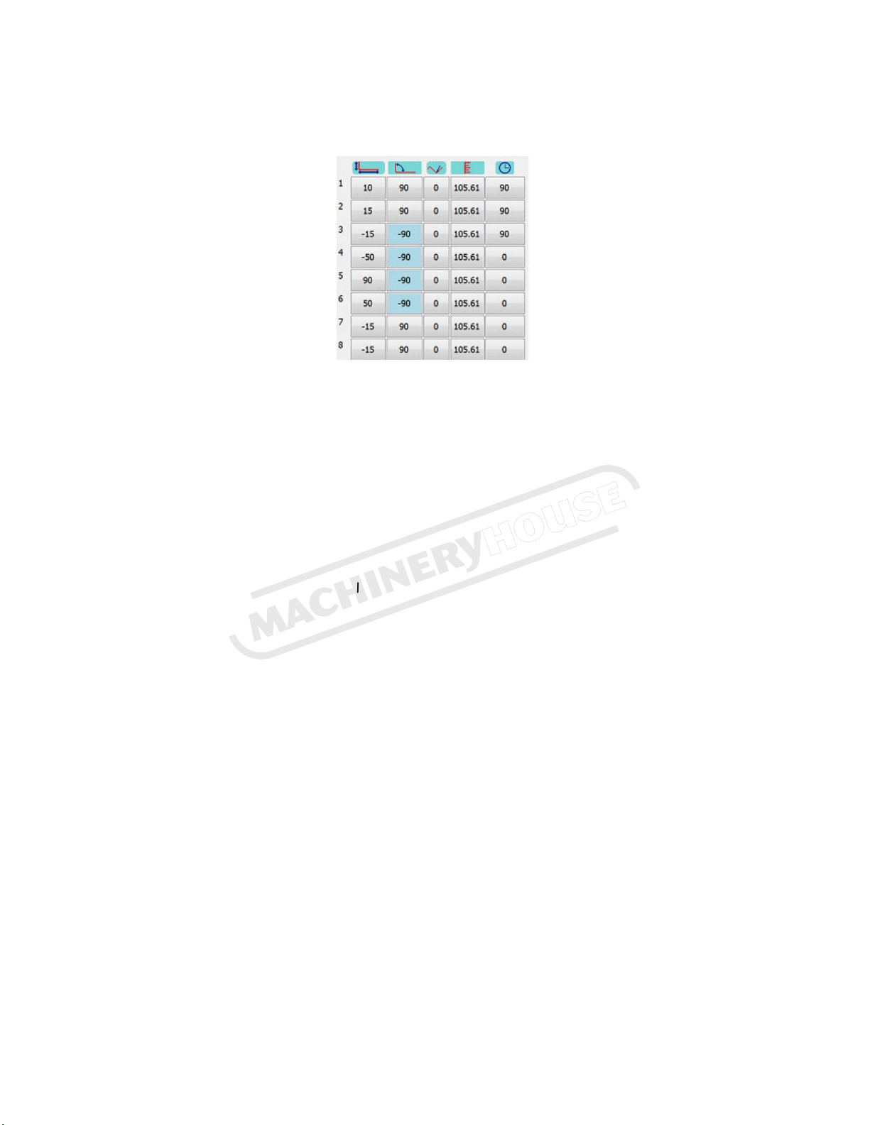
The data block is divided into 5 vertical columns from left to right.
From left to right is the dimension, angle, trim angle, tool depth and retract columns.
From top to bottom is the bend numbers of the profile from 1 to the total number of folds plus
one. This is because any profile has one more side than folds. The last dimension will not have an
angle.
1. ress on the top left hand cell, column 1, row 1. On the pop-up keypad, press “0” and “OK”
This will clear the whole data field.
2. Enter the first length 50
3. Enter the first angle 90
4. Enter the second length 150
5. Enter the next angle 90
6. Repeat steps 4&5 until all bends is entered.
7. Enter the last length 50
As you go along, the profile is drawn on the right so you can see what it looks like. If a certain
bend is on the wrong side of the material, change the sign of the angle to a negative for that
bend. For example if you draw a 2 bend profile as a U shape but you need a Z shape, change the
angle for bend 2 to negative. This means that the work piece will have to be turned over from
top to bottom. In the above example bend 1 & 2 is done on the top side (U shape). Change bend 2
to -90 to change to Z shape.
Page 4
Instruction Manual for PB-170B (S909F)
04/12/2014

3. Draw a new Job using Quic draw
ress the Quickdraw button and the following screen will appear.
Starting from the top left point of the profile above, touch the screen approximately on each
corner where you would like each bend to be, the points will automatically snap to the grid and
the values are rounded off. ress UNDO to redo a bend
Undo Removes last bend
Cancel Exit without using current Shape
Advanced use of Quickdraw can be found in section 21.
When you are happy with the shape press OK and you will be returned to the main screen, where
you can fine-tune the values easily simply by touching on the dimension or angle to be altered.
4. Editing sizes and angles
Touch on any dimension or angle on the profile and enter the new value on the pop-up keypad.
Page 5
Instruction Manual for PB-170B (S909F)
04/12/2014

5. Select Tools from the library
Touch on the top tool graphic on the main screen to go to the tool screen.
On this page, a new tool can be drawn up, named and saved. This is discussed in section 23. To
select a different tool from the library, press open.
Select the desired Tool. If there are more tools than one page, use up and down arrow.
ress CLOSE to return to Main page
Page 6
Instruction Manual for PB-170B (S909F)
04/12/2014

6. Select Dies from the library
ress on the die (bottom tool) graphic on the main screen to go to the Die screen.
On this page, a new Die can be created, named and saved as discussed in section 24. To select a
different Die from the library, press open.
Select the desired Die. If more Dies than one page, use up and down arrow.
ress cancel, then close to return to Main page.
ress on the V button to select the desired V (Material thickness X 8)
Page 7
Instruction Manual for PB-170B (S909F)
04/12/2014
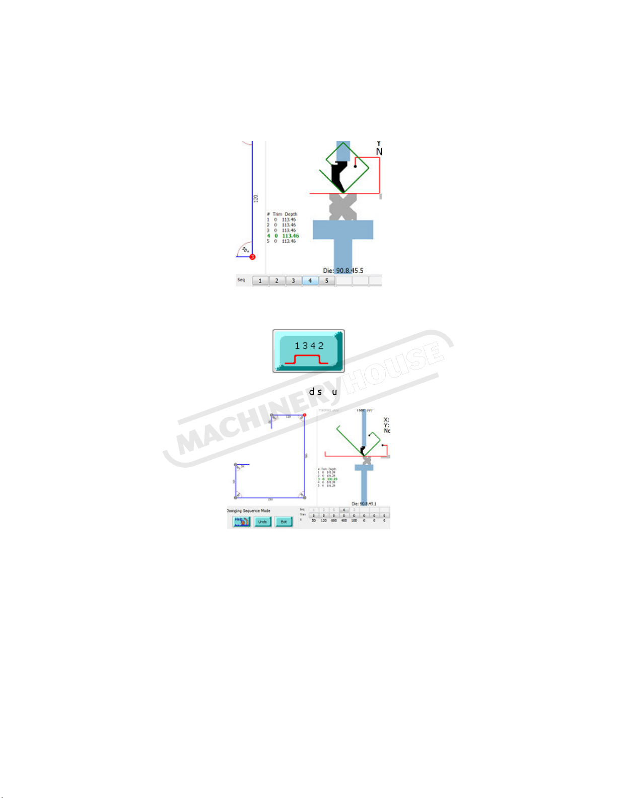
7. Step through job and find collisions
ress on the bend sequence numbers (Seq) below the graphic one after the other from left to
right and see how it will fold up and whether there are any collisions. As you step through the
numbers, the folding will be animated on the graphic
8. Alter the Bend Sequence
ress the bend sequence button to go to the bend sequence page
Touch on the first bend (red dot on profile), it will turn grey, then the next bend and the next
until complete. As you go along, you can see on the right how it would be folding. If the wrong
bend is selected, use the UNDO button. Alternatively, enter the bend sequence by pressing on
the bend numbers below the profile. Screen returns to main automatically after last bend
entered.
Page 8
Instruction Manual for PB-170B (S909F)
04/12/2014

9. Find collisions
Warning: If a bend sequence has been set before, it will be lost when pressing the Collusion
button. The collusions button will automatically step through bends ad if a collision is found, it
will alter the bend sequence in an attempt to avoid collusions.
ress the collusions button and it will attempt to find an alternative bend sequence
automatically if the default 1,2,3,4 creates a collision.
If it finds a workable bend sequence, it does not mean it will be the best or the fastest. A
manual bend sequence can be set in section 8
10. Select correct V width
ressing the V button will toggle between the different V’s on the current Die
11. Set Material Thic ness and width
Use the 2 buttons below to enter the correct thickness and width.
Page 9
Instruction Manual for PB-170B (S909F)
04/12/2014

13. Run job without material
After downloaded a job, press START for the machine to position. While X&Y axis (Ram- and
Backgauge) is positioning, a bar graph indicates while it is positioning
When in position, the bar graphs disappear and the machine is ready to fold. The X and Y values
in the top right hand corner will turn from red to green. Without inserting material, use the
foot switch to execute the folds until all folds are completed and the press is ready for the
first fold. Observe between every fold that the machine is positioning correctly.
Fold up the job with actual material. Check angles.
14. Correct under or overfolding
The third column from the left is the angle trim column. If a fold is 5 degrees under, enter 5
into the appropriate cell
If it overfolds, enter -5.
Look at the difference in Tool-depth column
(4th from the left) Fold 3 is a 90d
Fold 3 0 trim depth = 108.5
Fold 2 -2 trim = 108.25
Fold 1 +3 trim = 108.89
If the trim values is generally all high, lets say 8 degrees on average, it can be because the
tensile strength is different or maybe the V width is slightly larger than measured. It is then
better to change the tensile strength correction on the Die screen and use no or small trim
values. Refer to section 22.
Page 10
Instruction Manual for PB-170B (S909F)
04/12/2014

15. Name a Job
ress the Job name button and enter the job name on the popup keyboard below.
Bottom left is a button that switches between QWERTY style and ABC style.
ress OK when finished.
16. Save a Job
ress SAVE and you will be prompted if you want to overwrite the current job. ress YES and it
will ask for a password – enter 159.
Page 11
Instruction Manual for PB-170B (S909F)
04/12/2014
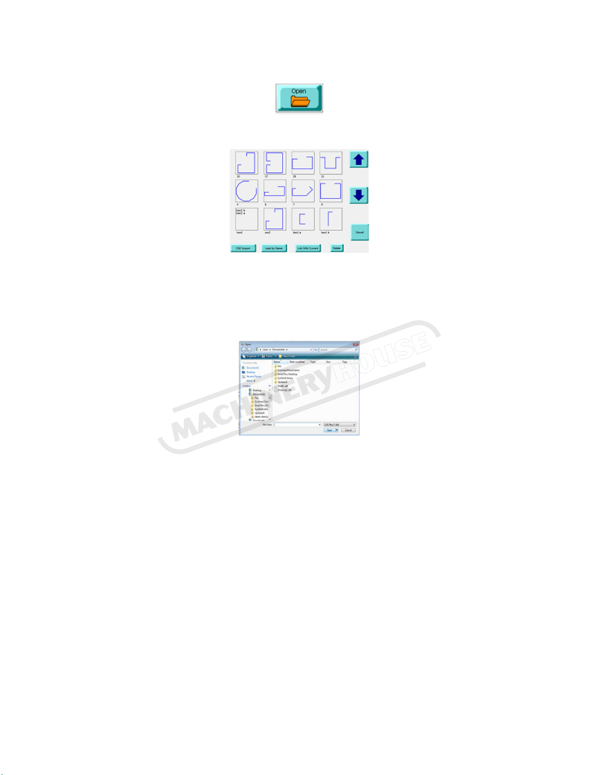
17. Open a Job
ress O EN and select a job from the list
You can also import a DXF file generated by a CAD program like Autocad, SolidEdge,
SolidWorks, Autodesk Inventer etc.
ress CAD Import to do this and select a job or change directory or select the office computer
if utilising a network.
Select the DXF file and press open. It will return with the new job on the Fasfold main screen.
Page 12
Instruction Manual for PB-170B (S909F)
04/12/2014
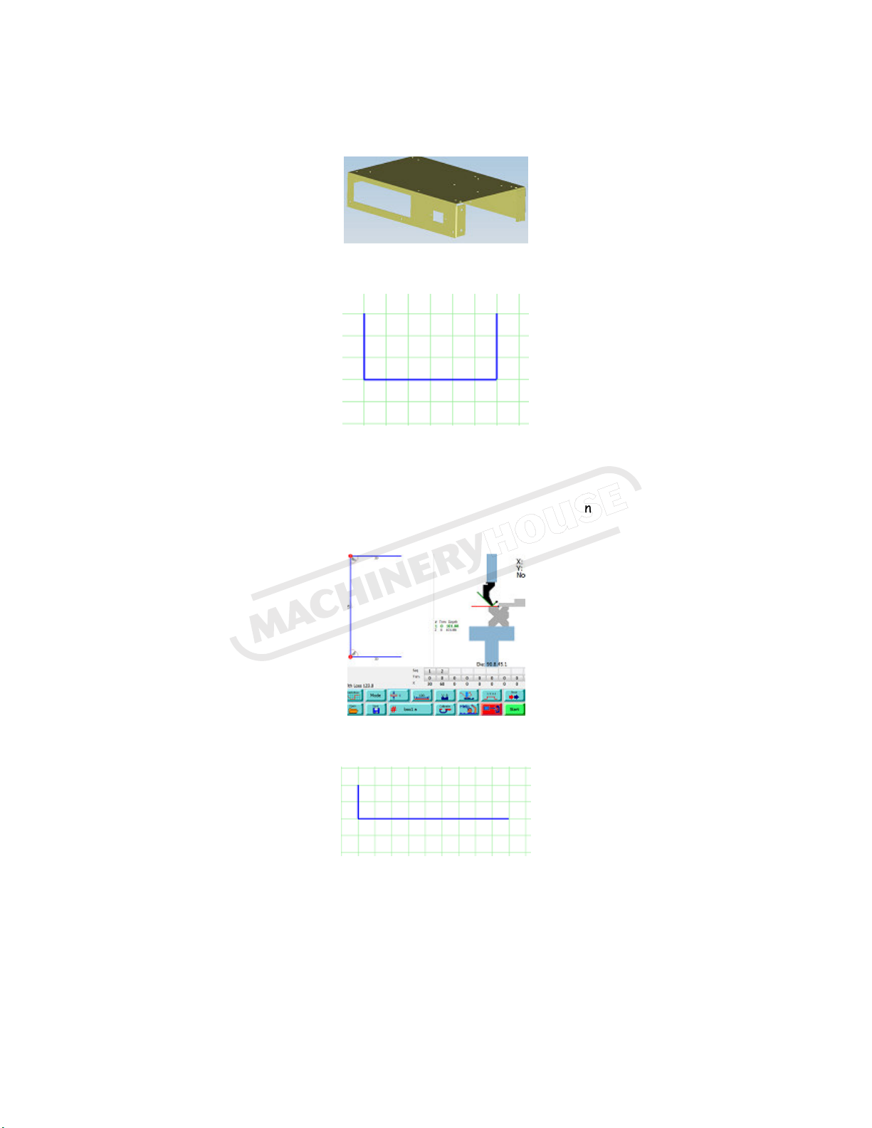
20. Box Mode
Lets program the box below.
Use QuickDraw to draw the Front view of the box above.
Edit the sizes on the profile on the main screen as described in section 4.
Set the right tooling, material thickness, width, bend sequence, name it Box1 a and save. Get the
right tooling on the machine and test fold the job to make sure the tooling is correct (alter trim
angles if necessary) and save.
Now draw up the side view and name it box1 b.
Edit the sizes on the profile on the Main screen. Get the right tooling on the machine and test
fold the job to make sure the tooling is correct and save.
Now link the 2 jobs together by pressing open, Link with current and press on box1 b if box1 a is
open already. If box1 b is already open, then link and open box1 a.
Page 13
Instruction Manual for PB-170B (S909F)
04/12/2014

If you press on the Box button below, it will toggle between A & B and the job will switch
between the front and side elevation on the profile and graphic.
ress Download and run the job. After the last fold on the A side, it will automatically switch to
the B side on the screen and position.
You can save this linked job as a complete job by pressing SAVE, and LINKED on the window.
This will save time in future linking 2 jobs
When you press O EN, previously linked jobs will be displayed as below left
Page 14
Instruction Manual for PB-170B (S909F)
04/12/2014

21. Quic Draw Advanced
If you would like to modify or edit a job you busy drawing up, there are a number of options:
Grid Size: The size of the grid squares
can be altered by changing the value in
the bottom left corner.
Edit: After pressing this you can see red dots
On each corner, press one you want to move
and it will highlight then press again to the
point you want to move it.
Undo: This will undo the last action.
Clear: Deletes all data and start again
22. Change Tensile strength correction
If large trim values are necessary due to tensile strength, enter a percentage tensile correction
on the DIE screen.
You can either directly enter a percentage by pressing on the Tensile correction button and
enter on the popup keypad or press Auto Correction, enter the desired angle as prompted and
then resulted angle. It automatically enters a tensile correction. When a job is saved, it saves
the tensile correction for that job.
Page 15
Instruction Manual for PB-170B (S909F)
04/12/2014

23. Program and save a new tool
From the Main screen, press on the top tool graphic which will take you to the Tool screen. From
there press QuickDraw which takes you to the Tool Quickdraw screen.
Starting from the bottom in a anticlockwise
direction, touch on each of the approximate corners to get the basic shape drawn.
The end point of the tool should be touched in the same spot as the start point to complete the
tool. ress UNDO if you make a mistake. ress OK to return to the Tool screen. You will be
prompted for the tool height. Enter this as the height from tool tip to the shoulder of the tool.
Actual sizes can now be edited on the data area on the left. Enter the radius of the tool, give it
a name and save.
Page 16
Instruction Manual for PB-170B (S909F)
04/12/2014

24. Program and save a new die
ress on the bottom DIE on the graphic to go to the DIE screen.
Type the overall dimension of the tool as SizeX and SizeY.
Now use the Data area on the left to enter the V sizes etc.
Before actually programming the new Die, lets use the above example to explain the Data area.
The fist column contains all the V sizes, 8,24,15,20 etc.
The next column contains the Angle for each V 86,70,86 etc.
The next column is the side number on the block. Top side is side1, then 2,3 & 4 in a clockwise
direction. To enter a side number, press on it and it will toggle from 1 to 4. It will not bring up a
keypad.
The last column is the offset which is the distance from the left edge to the centre of the V,
15,50,20,60 etc.
Now clear the whole data field by entering a zero into the top left cell.
Measure the V width of the first V and enter in line one, then angle, then side one, then the
distance from the left edge of the DIE to the centre of the V.
Now do the same for all the V’s
Name the Die and Save.
Tip: Use descriptive names such as 95.8.48 so it can be easily identified in future. 95 indicates
height, smallest V is 8mm and largest is 48mm.
Page 17
Instruction Manual for PB-170B (S909F)
04/12/2014

26. The Calibrate screen
The settings screen allows the
operator to change the how the
pressbrake and all of the axes
operate.
To open the settings screen press
calibrate on the main screen and
enter the password on the keypad
displayed.
The different sections are displayed
down the left hand side, the main
sections are Axis, Port, Machine, and
Program.
On the right is a diagram of the machine, showing the states of various switches attached.
Accepting or cancelling changes is done in the bottom left corner, this is also when you can access
the Commissioning Manager.
Axis:
The axis section controls the settings for each axis on the machine. Each axis can either be controlled
by the plc or a servo drive, or it can be not present on the machine at all.
Port:
The port section controls how the PLC and servo drives communicate with the Program. Some
machines may have different devices on different ports. Check with your supplier or CNC Auto to
verify these settings.
Machine:
The settings that belong to the machine rather than a specific axis appear in this section.
Program:
The settings that belong to the program rather than the machine appear in this section.
Page 18
Instruction Manual for PB-170B (S909F)
04/12/2014

27. Calibrating the Port
Most of these settings will already be set up for you or given to you by your supplier.
A port can either be Not Present or a Serial
port, which can be selected from the top of
the screen. This applies to the port selected
in the Ports section.
Protocol:
The protocol defines the way the PLC and
Servo Drives communicate with the PC. The
options for the protocol are: RS 85 RTU
(default), RS 85 ASCII, and RS232 ASCII.
Note: RS232 ASCII only supports one PLC or
Servo Drive.
Device:
The device specifies the physical port the PLC and Servo Drives are connected to.
Baud Rate:
The Baud Rate specifies the speed of communication on the COM port, measured in bps (bits per
second).
Data Bits:
The number of data bits for communications. Options are: 5, 6, 7, and 8 (default).
Stop Bits:
The number of data bits for communications. Options are: 0, 1 (default), 1.5, and 2.
Parity:
The parity for communications error checking. Options are: None, Odd, Even (default), Mark, Space.
Note: None, Mark, and Spa e options do not he k for errors.
Handsha e:
The Handshaking for communications. Options are: None (default), X on / X off, Request to send,
Both.
Encoding:
The encoding for communications. Options are: None, Odd, Even (default), Mark, Space.
Page 19
Instruction Manual for PB-170B (S909F)
04/12/2014

28. Calibrate Servo Drives
The Servo Drive option can be selected on
the top of the screen when an axis is
selected in the Axis.
Port:
This is the port that the PC will use to
communicate with the Servo, to setup the
port see the Calibrating Ports help file.
Address:
This is the address that is assigned to the
servo, to distinguish it from the other Servo
Drives or PLCs on the same port.
Actual Position:
This is the position that the Axis connected to the servo drive is currently at (measured in mm).
Calibration Factor:
This is the factor used to convert from the Servo Drives encoder pulses to an actual measurement
(mm per pulse).
Full Rotation:
The number of encoder pulses in a full rotation of the Servo Motor.
Tollerance:
This is the tolerance of the measurement from the Servo Drive.
Fast Speed:
This is the speed the Servo Motor moves at provided it is not close to the target.
Slow Speed:
This is the speed the Servo Motor moves at when it is close to the target.
Servo Settings:
This is used to set up the Servo Drives with defaults
from Fasfold.
Note: Ea h of these options requires the Servo Drive
be reset (turned off and then on) to take effe t.
Note: It is re ommended that you omplete the
operations in this order.
Factory Defaults:
This option resets the Servo Drive to the Factory
Default settings.
Page 20
Instruction Manual for PB-170B (S909F)
04/12/2014
Table of contents
Other MetalMaster Lathe manuals


