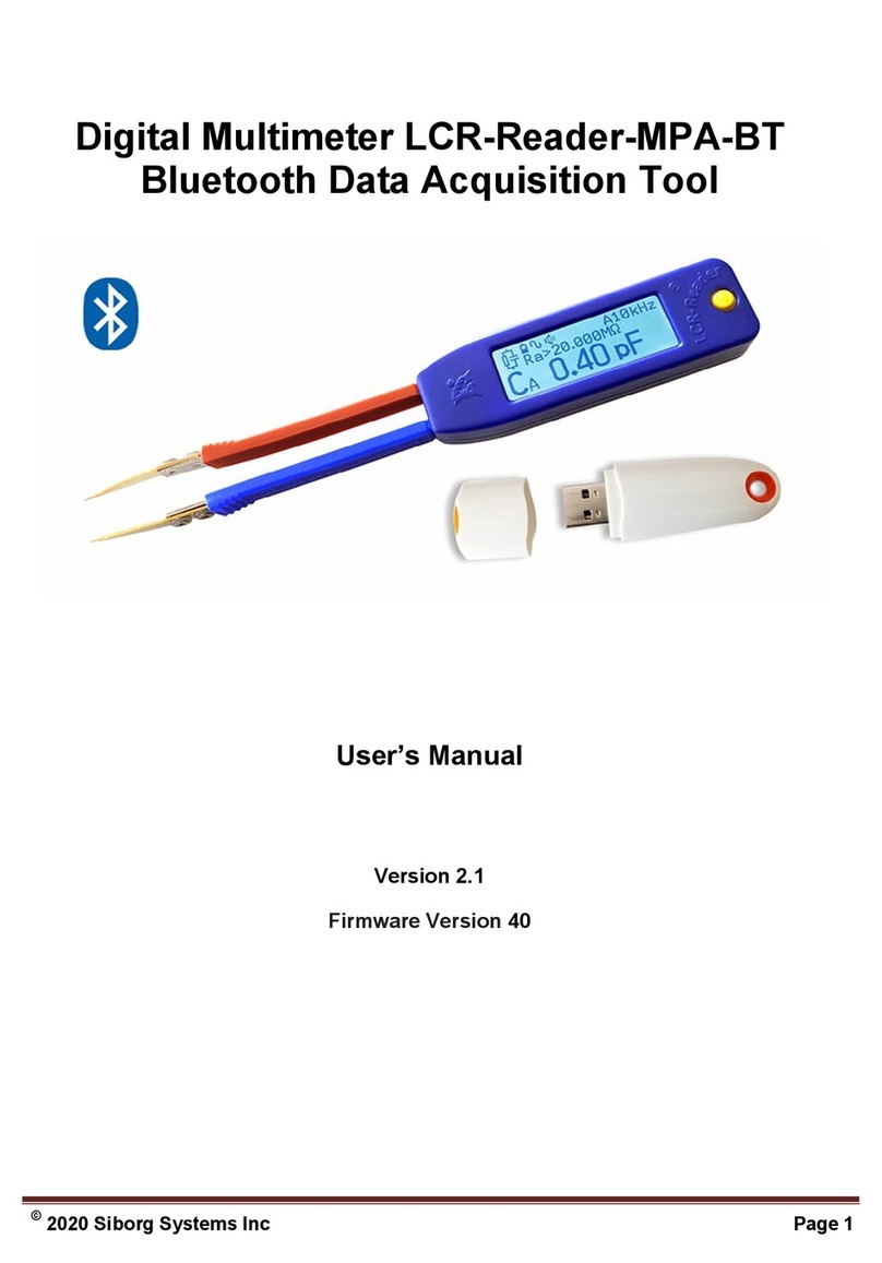
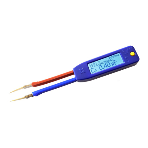
Siborg LCR-Reader-R2 User manual

1

1 Device Use 2
1.1 Main Features 2
2 What is included in the package 3
3 Symbols and Abbreviaons 3
4 Principle of Operaon 3
4.1 Calculaon of Parameters: 4
5 Safety Measures and General Instrucons 5
6 Device Controls 6
6.1 Turning On the Device 6
6.2 Turning Off the Device 6
6.3 Charging the Baery 6
6.4 Main and System Menu 6
7 Modes of Operaon 8
7.1 R-L-C-D Mode 8
7.1.1 Measurements 9
7.1.2 Quick Controls 10
7.1.3 Relave (Tolerance) Measurements 10
7.1.4 Open/Short Calibraon 10
7.1.5 Capacitance Offset Calibraon Board 11
7.2 R-L-C-D mode menu 11
7.2.1 Primary Parameter 11
7.2.2 Secondary Parameter 12
7.2.3 Test Frequency 12
7.2.4 Test Signal Level 12
7.2.5 Period 12
7.2.6 SER/PAR Mode 12
7.2.7 Sound 13
7.2.8 Source Impedance 13
7.2.9 I-V Curve 13
7.2.10 Cap-Voltage 14
7.2.11 Data Hold 14
7.2.12 Power Save Mode 14
7.2.13 Default 14
7.2.14 Large Cap 15
7.2.15 Large Cap (0.5 μF to 40 mF) Sengs 15
7.2.16 Super Large Cap > 40 mF Measurement 16
7.3 RDC+LED Mode 16
1 © Copyright Siborg Systems Inc.

7.3.1 Auto Mode 16
7.3.2 Diode Mode 16
7.3.2 R test at 1.3 V and R test at 100mV 17
7.4 Signal Generator Mode 17
7.4.1 Controls 17
7.5 System Menu Entries 17
7.5.1 Power 17
7.5.2 Sound 18
7.5.3 Display 18
7.5.4 Serial Number 18
7.5.5 Default 18
8 Device Troubleshoong 18
8.1 If the device does not turn on 18
8.2 If there are no inial readings on the screen 18
8.3 Technical Support 19
9 Maintenance 19
9.1 General care of the device 19
9.2 Repairs 19
10 Storage Condions 19
11 Transportaon 19
12 Warranty 19
13 Specificaons 20
13.1 Overview 21
13.2 FCC Compliance 21
13.3 General Informaon 21
13.4 Details of the Measurement Modes 22
13.4.1 Test Signal Generator 22
13.4.2 Resistance 22
13.4.3 DC Resistance 22
13.4.4 Capacitance 23
13.4.5 DC Capacitance Measurement 23
13.4.6 Inductance 23
13.4.9 Low Frequency DDS Signal Generator 24
13.5 Supplement A 24
13.6 Supplement B 25
© Copyright Siborg Systems Inc. 2

1 Device Use
1.1 Main Features
● Automac component recognion L-C-R-Diode
● Basic Accuracy of 0.1%
● DC measurement of Resistance and Capacitance up to 1 F
● Pass/No Pass Electrolyte Cap indicaon with Built-in Rejecon
table
● Automac/manual frequency seng 100, 120 Hz, 1, 10, 100
and 250 kHz
● Automac adjustment of test signal to 0.1 V peak-to-peak for
in-circuit measurements
● Designated ESR measurements
● Easy Open/Short calibraon for beer measurement accuracy
● Automac detecon of diode polarity and short circuit
● Frequency meter
● Four-way joysck control
● Mulple Parameter Display: primary/secondary, etc.
● Automac/Manual Right/Le hand screen orientaon
● Sound indicaon
● Baery discharge warning, full charge indicaon
● Automac power off
● Baery charge indicator
● Backlit LCD
2 What is included in the package
LCR-Reader R2
Case
Capacitance Offset Calibraon Board
Spare Ergonomic Bent Test Leads*
Spare Baery*
Kelvin Probe Connector*
* Oponal Accessories
3 Symbols and Abbreviaons
DUT – Device Under Test
ESR - Equivalent Series Resistance
Low ESR - Ultralow Equivalent Series Resistance
Rs - Series Resistance
Ls - Inductance in series connecon
Cs - Capacitance in Series Connecon
Xs - Reactance in Series connecon
Rp - Resistance in Parallel connecon
Lp - Inductance in Parallel Connecon
Cp - Capacitance in Parallel Connecon
Xp - Reactance in Parallel Connecon
Q - Quality Factor
D - Loss Tangent
θ – Phase angle
3 © Copyright Siborg Systems Inc.

RMS - RMS value
TRMS – True RMS Value
LF - Low Frequency
Z - Impedance
| Z | - Impedance Module
DDS - Direct Digital Frequency Synthesis
DC - DC Voltage
AC - Alternang Voltage
4 Principle of Operaon
Fig. 1 shows the LCR meter block-diagram. Voltage from the
voltage source through a liming 100 Ω resistor is applied to the
DUT connected at points A and B. The amplitude and frequency
of the Test Signal V are adjustable. It is also possible to apply
either posive or negave DC voltage to the DUT. A voltage drop
on the DUT is measured by DAu. The voltage drop on resistor Rj
measured by DAj is proporonal to the current flowing through
the measured component. Aer digizing the ADC signals the
impedance is calculated according to the formula DUT
impedance Z =Rj* Vau/Vaj.
Inial values of Impedance (offsets) obtained during calibraon
with Open and Short probes are stored in the non-volale
memory of the device and are considered in the calculaon of
the impedance of the measured component thus eliminang the
offsets due to the device internal parasics.
The measured component can be represented as one of the
following equivalent circuits:
(1) and (2): AC measurement series circuits, (3) and (4): AC
parallel circuits, (5,6,7) DC measurement of diodes, resistance
and capacitance.
Impedance in series circuits is Z = Rs + iXs and in parallel circuits
is Z = 1/(1/Rp + 1/iXp) where Xs (Xp) < 0 if the reactance is
Capacive and at Xs (Xp) > 0 the reactance is Inducve.
4.1 Calculaon of Parameters:
Capacitance C = 1/(2π f |Xs|) where f is the test frequency.
Inductance L = Xs/(2π f ). Q = |Xs|/Rs. D = 1/Q. |Z| =
© Copyright Siborg Systems Inc. 4

In automac mode the device automacally selects the opmum
frequency and the equivalent circuit for measurements. Users
can also manually select measurement mode and frequency of
the test signal can be selected a range of fixed values from 100
Hz to 250 kHz. Test voltage can be set to 1.0, 0.5 and 0.1 Vrms.
By passing direct current through the measured component, the
voltage and current can be measured. Using Ohm’s law, the DC
current Resistance (RDC) is calculated.
By applying the DC voltage in forward and reverse direcon, the
diodes are detected, and the polarity of p-n juncon is
determined.
For capacitors larger than 40 mF the capacitance is calculated
using the voltage variaon on the measured capacitor when it is
charging for a certain me interval and applied current.
The principle of the frequency meter is based on the counng of
pulses of the reference generator between the two ramps of the
input signal for a certain period of me (by default about 1
second). At the same me, the quanty of periods of the input
5 © Copyright Siborg Systems Inc.

signal is counted too. Then the frequency f is calculated by the
formula f = M/N* f
r where M is the number of periods of the
input signal, N is the number of pulses from the reference
generator and f
r is the frequency of the reference generator.
The principle of measuring the voltage is based on comparing the
input signal with the reference voltage.
5 Safety Measures and General Instrucons
For safe and reliable operaon of the device, follow these rules:
1. Never do measurements in a live circuit
2. Never apply voltage to the probes
3. Never measure Charged Capacitors
4. Do not make measurements while the device is charging
5. Charge the baery using a USB port of a computer or a DC
charger 5 V +/- 5%. Do not use damaged cables or chargers.
6. Do not stretch the handles for more than 20mm between
the test leads.
7. This device is designed for indoor use only.
8. To prevent injury from sharp ends of the test leads,
transport the device in the case provided.
9. Do not touch non-insulated test lead surfaces during
measurements, it will affect the result. Keep fingers on the
insulated surfaces of the handles.
10. Replacement of the baery must be carried out by a
specialist. Baeries must be recycled or disposed of
separately from regular household waste. Do not burn the
baery.
6 Device Controls
The device is controlled by a 4-way joysck. Joysck funcons are
different when it is held for 1, or 2 beeps. Figure below shows
the joysck locaon on the housing with arrows indicang the
push direcons and the number of beeps required to call the
funcon.
The arrows show the direcon of the joysck push. A single
arrow denotes holding for one beep, two arrow heads denote
holding for two beeps before releasing.
6.1 Turning on the Device
Press the joysck and hold for 1 beep.
© Copyright Siborg Systems Inc. 6

6.2 Turning Off the Device
The device will turn off in the following cases:
1. Press the joysck and hold it unl the display shows
“Shutdown”.
2. The device turns off if it has been inacve for 120 seconds
(default). The automac turn-off me seng can be changed
in the menu: System /Power/Time Off
6.3 Charging the Baery
The device is powered by a Li-Po baery with 3.7 V rated voltage.
The baery icon on the display shows the remaining charge of
the baery. This icon will blink when
the device’s power is below 3.6 V and
will automacally turn off at 3.5 V.
Informaon about the baery voltage can be displayed by
selecng: System/Power/Baery Voltage
Charge the baery by connecng it via a micro-USB cable
to a USB DC voltage source of 5V +/- 5%. The device screen is lit
when the device is charging, and it turns off when the charging is
complete.
6.4 Main and System Menu
The main menu is shown when the joysck is pressed. The main
menu is mul-levelled. Select the appropriate menu item by
moving the joysck up or down and pressing down to select.
To set the default operang mode (R-L-C-D, RDC+LED, Voltage,
etc.), press and hold the joysck for two beeps. This mode is then
stored in the device memory and will be acvated when the
device is powered on next me.
7 © Copyright Siborg Systems Inc.

7 Modes of Operaon
7.1 R-L-C-D Mode
R-L-C-D mode is the default device mode and it is designated for
measurement of Resistors, Capacitors, Inductances and Diodes.
To select the mode, select R-L-C-D in the main menu. In order to
get access to the mode parameters (hidden sub-menu) push the
joysck to the right for one beep. A typical screen for R-L-C-D
mode looks as follows:
© Copyright Siborg Systems Inc. 8

7.1.1 Measurements
When the measured component is connected to the test leads,
the screen displays informaon depending on the component
and the selected sengs in the R-L-C-D mode menu.
Inductance Capacitance
Resistance Diode
In automac mode, measurement of capacitance larger than 0.9
μ F by default is made at 120 Hz, while ESR is measured at 100
kHz. In this case the display looks
as follows. The frequency is not
shown on the screen, but two
addional numbers are displayed indicang the capacitor
parameters described below.
The main criterion for rejecon of electrolyc capacitors is the
value of ESR that varies amongst the types of capacitors and
manufacturers. Two ESR tables have been compiled with typical
ESR values for various capacitances/voltages, one for regular
electrolyc capacitors and the other for Low ESR capacitors
(presented below in Supplement A and B). These are indicave
values and should only be used for a rough esmaon of the
capacitor performance. In this case besides the measured ESR
value, two addional numbers are displayed in the right top
poron of the screen. The first number indicates the quality of
the capacitor measured as a ln(Rs/Rt) where Rs is the measured
ESR value and Rt is the value from the table. For standard
aluminum capacitors a posive number indicates rejecon,
whereas for Low ESR values above -10. The 2nd number is the
selected operang voltage of the capacitor. It should be specified
in the menu item Large Cap/C-voltage . It should also be kept in
mind that the measured capacitance may be significantly lower
than the original data from the data sheet due to evaporaon of
the electrolyte and other degradaon mechanisms. In such cases
the table cannot be used for accurate capacitor evaluaon.
If you wish to measure capacitance larger than 0.9 μ F at a
specific frequency you have to adjust frequency by pushing the
joysck to the le for one beep or select frequency in the R-L-C-D
parameter sub-menu by pushing the joysck to the right for one
beep to acvate the hidden sub-menu. In this case both the
capacitance and the secondary parameter (ESR or D) are
9 © Copyright Siborg Systems Inc.

measured at the same selected frequency.
Discharge Capacitor!
7.1.2 Quick Controls
● Push the joysck up and hold for 1 beep to change the primary
impedance type (more info below, Secon 7.2.1)
● Push the joysck to the right and
hold for 2 beeps to make
Open/Short calibraon and
eliminate the offsets.
● Push the joysck le and hold for 1 beep to change the test
frequency. The frequency changes cyclically
Auto-100Hz-120Hz-1kHz-10kHz-100kHz. If the frequency is
selected from the menu in the range 20-75kHz, the frequency
changes cyclically
20kHz-30kHz-40kHz-50kHz-60kHz-75kHz-100kHz
● Push the joysck down and hold for 1 beep to change the test
signal level cyclically Auto-1.0-0.5-0.1 Vrms
7.1.3 Relave (Tolerance) Measurements
In order to iniate Relave (Tolerance) measurement mode,
connect the measured reference component to the probes, push
the joysck up and hold for 2 beeps. The reference value will be
recorded, and further measurements will show the measured
value as well as the percentage deviaon from the reference
value. To cancel Relave measurements, push the joysck down
for two beeps.
7.1.4 Open/Short Calibraon
Before the first use, the device must be calibrated with Open and
Short probes for both RDC+LED (for a correct diode parameter
extracon) and R-L-C-D mode for each test frequency. When the
device is set to Auto-frequency the device is automacally
calibrated at 100Hz, 120 Hz, 1 kHz, 10kHz, and 100kHz.
If the probes are shorted, parasic resistance is obtained and
accounted for. If the probes are open, parasic capacitance is
obtained. Please use LCR-Reader Capacitance Calibraon Board
to set a proper distance between the test leads for Open circuit
calibraon (according to the component size) because the
parasic capacitance depends on the distance between the test
leads. Short circuit calibraon is very crucial for small resistance
and inductance and large capacitance. Open circuit calibraon is
crucial for small capacitance and large resistance.
To eliminate the offset, push the joysck to the right, hold for 2
beeps and release. When measuring small capacitances less than
100 pF, use LCR-Reader Offset Calibraon Board included in the
package for the open calibraon. Insert the test leads at the
© Copyright Siborg Systems Inc. 10

distance of the size of the component and calibrate with open
probes. Only then measure the capacitor.
Before measuring small inductances (less than 10 μH) and
resistances (less than 10 Ω) wipe off the ps of any dirt and
oxides and calibrate with short probes.
7.1.5 Capacitance Offset Calibraon Board
The Capacitance Offset Calibraon Board provides a reliable
method of determining the parasic offset between the test
leads. The dummy PCB uses holes to represent various sizes of
components.
To use the calibraon board, place the test leads into the holes
corresponding to the size of the component under test; make
open calibraon by pushing the
joysck to the right, hold for 2
beeps and release.
7.2 R-L-C-D mode menu
To open the hidden R-L-C-D mode
sengs push the joysck to the right
and hold for 1 beep, the following
menu will appear. The menu tree is
shown in detail in the following
diagram:
11 © Copyright Siborg Systems Inc.

7.2.1 Primary Parameter
In Auto mode the type of measured component is determined
automacally: R: Resistor, L: Inductance, C: Capacitor, D: Diode. In
addion to the component type selecon test signal level is also
adjusted when in-circuit measurements are made (see below
7.2.4). Measurement mode can also be set manually to R, L, C, Z
and Large Cap. The last mode is only for measuring capacitance
values larger than 0.5 μF (see secon 7.2.14 below).
7.2.2 Secondary Parameter
In Auto mode for inductors quality Q factor is displayed for Q>1
and series Resistance Rs for Q<1, and for capacitors, loss tangent
for C < 0.5 μF and ESR for C >0.5 μF. Automac secondary
parameter selecon does not work if the Test Signal is set to
Auto, Rs or Rp are used as the secondary parameter in this case.
7.2.3 Test Frequency
This menu item allows you to manually select the frequency of
the test signal. In Auto mode, the device automacally selects a
frequency of 100Hz, 1 kHz or 10 kHz, depending on the rang
and type of the component. For electrolyc capacitors 120 Hz is
used for capacitance measurements and 100kHz for ESR. Users
can also manually select the test frequency. A higher frequency
should be used for measuring small values of capacitances and
inductances as well as ESR. Lower frequencies are used to
measure large inductance and capacitance values. Resistance
measurements are always made at 1 kHz unless RDC+LED mode
is selected.
7.2.4 Test Signal Level
For more stable readings, select 1.0 Vrms or Auto signal level.
Auto is best for measuring loose components and in-circuit
measurements of R, C, L. When measuring a component on a
PCB, high test signal may open p-n juncons of semiconductor
components. This, in turn, may cause errors in the
measurements. In order to avoid
the effect of p-n juncons, the
signal level is automacally
reduced to 0.1 V peak-to-peak and
the impedance is re-measured. In this case, the screen shows the
diode symbol and the direcon of the p-n juncon as shown
below.
7.2.5 Period
Increased measurement me results in more stable readings,
reduced me results in faster updates on the screen.
7.2.6 SER/PAR Mode
This is used to select the equivalent circuit depending on the
characteriscs of the element. For Capacitance measurements in
© Copyright Siborg Systems Inc. 12

Automac equivalent circuit regime and Auto signal level Serial
circuit is used for impedance values lower than 100 Ohms. If
signal level is not in the Auto regime, serial equivalent circuit is
used for impedance values lower than 1 kOhm. For inductance
only serial mode is used unless parallel mode is explicitly
specified.
7.2.7 Sound
The device will beep when the resistance is less than 10 Ω, or a
short circuit is found.
7.2.8 Source Impedance
Auto – 100 R – 1600 R
7.2.9 I-V Curve
When this mode is selected, the device will switch to Analog
Signature Analysis (ASA or I-V tesng). This is a troubleshoong
technique where current-limited AC sine wave is applied across
two points to locate damaged and marginal components.
The display plots the voltage across the device under test as the
horizontal axis and the current as the vercal axis. Different
signatures are produced depending on the current flow as the
applied voltage changes.
The four basic signatures are displayed Resistance, Capacitance,
Inductance and Semiconductor:
Resistance is displayed as a straight line at an angle from 0 to 90
degrees with the slope
depending on the resistance.
The higher the value of
resistor, the closer the line
will get to the horizontal (an open circuit)
Capacitance is displayed as a circle or ellipse. A low value
capacitor will have flaened,
horizontal ellipcal
signatures; a capacitor with
high values will have
flaened, vercal ellipcal
signatures. Signature of an ideal capacitor would be nearly a
perfect circle.
Inductance is displayed as circular or somewhat ellipcal due to
parasic resistance.
Inductors are displayed as
flaened, horizontal ellipses;
an ideal inductor would
produce a perfect circle.
Inductors generally require low source impedance and higher
test frequencies to display a nice ellipcal signature.
13 © Copyright Siborg Systems Inc.

Semiconductors/diodes are
displayed as two or more line
segments that resemble a
right angle showing both
forward and reverse bias. The vercal segment displays the
forward bias region and the turn-on voltage and drop; the
horizontal part of the curve is the reverse voltage region where
the diode is effecvely an open-circuit and non-conducng.
Shorts are displayed as vercal lines because the current flow is
theorecally infinite; an open circuit would display as a horizontal
line due to the current always being zero.
7.2.10 Cap-Voltage
This seng must be selected in
the menu when evaluang
electrolyc capacitors for
rejecon by ESR value. The
voltage value should be taken
from the capacitor’s housing. If
OFF is selected, the capacitor parameters such as the capacitor
quality according to the table and nominal voltage will not be
shown on the display
7.2.11 Data Hold
When selected, the device will hold measurement data on the
screen. A beep will sound when the measurement is made, and
the values are held on the screen aer the component has been
disconnected from the device. The device will only reset when a
new component is measured, or the test probes are shorted.
In order to set a default measurement mode that will be
acvated when the device is turned on next me, select the
mode, press the joysck and hold for 2 beeps. This measurement
seng will be stored in the device’s non-volale memory for all
other measurements unl selecng other parameters or Default
in the menu.
7.2.12 Power Save Mode
On/Off/Exit
7.2.13 Default
By selecng Default, the R-L-C-D mode parameters are reset to:
● Primary Parameter is Auto
● Secondary Parameter is Auto
● Frequency is Auto
● Signal Level - 1.0 Vrms
● Measurement Time: 0.5 seconds
● Equivalent Scheme is Auto
© Copyright Siborg Systems Inc. 14

● Sound is On
● C-voltage is Off
● Data Hold is Off
If you hold the joysck up to 2 beeps, then all parameters are
stored in the non-volale memory and will be loaded when the
device is powered on.
7.2.14 Large Cap
In this mode, there are two
sub-modes, one for capacitance
values from 0.5 μF to 40 mF and
the other from 40 mF to 1 F. In the
first mode the capacitance is measured at a frequency of 120 Hz,
and the capacitor's ESR is measured at the frequency of 100 kHz.
The other mode is for capacitance values from 40 mF to 1 F and
the capacitance is measured using DC while ESR is sll measured
at 100 kHz. To toggle between the modes, push the joysck le
for 1 beep.
Discharge Capacitor!
Before the first applicaon in this sub-mode it is necessary to
addionally calibrate the device with both open and shorted
probes.
For the rejecon of electrolyc capacitors based on ESR, two
tables are stored in the memory of the device, one for standard
aluminum capacitors and the other for Low ESR capacitors
(Supplement C and D, Secon 14.2 and 14.3). Two addional
numbers are displayed at the top-right corner of the screen in
this case: the first number is the quality of the capacitor. For
standard aluminum capacitors, posive values indicate rejecon,
and for Low ESR rejected values are above -10. The second
number is the selected operang voltage of the capacitor in
menu under C voltage: 6.3, 10, 16, 20, 30, 50-63, 100, and 160+
Volts.
7.2.15 Large Cap (0.5 μF to 40 mF) Sengs
● Push the Joysck right for 2 beeps to make calibraon
eliminang the offset. Only short calibraon is required.
● Push Joysck to the le to toggle between lower than 40 mF
and higher than 40 mF capacitance measurements. To speed
up the seling of the readings, short the capacitor leads for 2-3
seconds before the measurements.
● Push Joysck down for 1 beep to
toggle the test signal level
between 1.0 Vrms and 0.1 Vrms
15 © Copyright Siborg Systems Inc.

7.2.16 Super Large Cap > 40 mF Measurement
• Push the Joysck right for 2 beeps to make calibraon
eliminang the offset. Only short
calibraon is required.
• Push Joysck to the le to toggle
between lower than 40 mF and
higher than 40 mF capacitance measurements. To speed up the
seling of the readings, short the capacitor leads for 2-3
seconds before the measurements.
• Push Joysck down for 1 beep to toggle the test signal level
between 1.0 Vrms and 0.1 V Vrms Discharge Capacitors
7.3 RDC+LED Mode
This mode is designed to measure DC resistance, parameters of
Diodes/LEDs, and diode leakage currents. Besides, it allows
measuring a shunt resistor on a board that can be used for
evaluang the current via that shunt in a live circuit.
• Press the joysck to open the main menu, select RDC+LED
mode and press the joysck again.
• Before making any measurement, push the joysck to the right
for 2 beeps to calibrate with open and short probes to
eliminate the offsets.
Four sub-modes can be selected: Auto, Diode, R test at 1.3 V DC,
R test at 100 mV DC.
7.3.1 Auto Mode
To select the Auto Mode push the joysck down.
In the Auto mode resistances and diodes are automacally
detected. For resistors the boom line displays the resistance of
the connected element, at the top the current Ir flowing through
it. For diodes, the polarity of the diode, the voltage drop in the
open state and the reverse current Ir are displayed.
7.3.2 Diode Mode
To select the Diode Mode push the joysck le. If you push le
once again, the diode polarity reverses.
Diode mode is used for LED/diode parameter extracon using DC
bias. It is recommended for in-circuit characterizaon of p-n
juncons. The screen displays the voltage drop in the open state
when the forward bias is applied. If the reverse bias is applied, OL
is displayed instead. Push the joysck to the le and hold for 1
beep to change the polarity of the probes.
© Copyright Siborg Systems Inc. 16

7.3.2 R test at 1.3 V and R test at 100mV
To select the R-test Mode push the joysck up, resistor symbol
will be displayed in the top le corner. If you push up again, the
test voltage toggles between 1.3 and 0.1 Volts. The applied
voltage is indicated by the pulse height in the top row of the
screen.
These modes are used to measure DC resistance, recommended
for in-circuit detecon of resistors. It also allows measuring the
selected shunt resistor on the board that could be later used for
current measurements. In order to set the shunt resistor value,
push the joysck down unl 2 beeps while measuring the shunt
resistor.
7.4 Signal Generator Mode
Only Sine wave signals are
generated. The signal is applied to
the device probes. It is possible to
adjust the span (peak-to-peak) of the signal from 0.1 to 3.0 V.
Parameters are stored when exing the mode. On the right of the
screen the voltage span and the waveform icon are shown. The
frequency in Hz is displayed in the center of the screen.
In this mode, the turn-off me is 4 mes longer than the default
in other modes. An external decoupling capacitor is required to
supply a signal to an acve circuit. It should be connected to the
Blue probe. The Red probe is common, virtual ground. In this
mode, the device does not turn-off by "flipping" and the funcon
of automac change of the display orientaon (le/right hand) is
disabled. It is recommended to use LCR-Reader Kelvin Probe
Connector to simplify the device operaon in this mode.
7.4.1 Controls
● Push the joysck to the le or right for 1 beep to select the
item to change.
● Push the joysck up/down for 1 beep to increase/decrease the
selected parameter.
7.5 System Menu Entries
7.5.1 Power
Baery Voltage
Turn-off Time: Push joysck Up/Down to Increase/Decrease
17 © Copyright Siborg Systems Inc.

Exit
7.5.2 Sound
Loud/Moderate/Quiet/Exit
7.5.3 Display
Hand: Right/Le /Exit
Contrast: Push joysck Up/Down to Increase/Decrease Contrast
Brightness: Push joysck Up/Down to Increase/Decrease
Brightness
Exit
7.5.4 Serial Number
Press the joysck to display the Serial Number of the device and
the Firmware version.
7.5.5 Default
The following sengs are stored in the device EEPROM when
Default is selected in the System Menu and the joysck is
pressed:
● Primary Parameter Auto
● Secondary Parameter Auto
● Frequency Auto
● Signal Level 1.0 Vrms
● Measurement Period 0.5 s
● Equivalent Circuit Auto
● Sound On
● Data Hold Off
● Shutdown Time 120 s
● Wakeup Mode R-L-C-D
● RDC+LED Mode Auto
● Frequency Measurement Time 1 s
● System Sound Medium
● All offsets are reset to zero
8 Device Troubleshoong
8.1 If the device does not turn on
● Push the joysck and hold it for 1 beep, then release it.
● Charge the baery.
● Contact the manufacturer for repair.
8.2 If there are no inial readings on the screen
● From the system menu, select Default.
● Clean the contacts and make open/short calibraon with open
and closed probes.
● Review this manual to find possible errors in operang the
device.
8.3 Technical Support
Customers can contact customer support by phone
+1-519-888-9906 or by e-mail support@LCR-Reader.com.
© Copyright Siborg Systems Inc. 18

When contacng technical support, please provide the following
informaon:
● Model number
● Soware version number
● Serial number of the device
● Purchase Receipt
9 Maintenance
9.1 General care of the device
● Do not expose the device to water, it is not waterproof.
● Do not expose the display for a long period of me to direct sunlight.
● Use a so cloth dampened with water to clean the outside surface and
clean the LCD display.
● Do not use liquid solvents or detergents.
9.2 Repairs
If there is an unexpected measurement result, check the quality of the
contact between the test leads of the device probes and the element
being examined. Make sure you make the measurements correctly. Carry
out the instrument diagnoscs. Independent dismantling of the case,
replacement of individual elements and circuits are not allowed. For a
repair, please contact the manufacturer directly.
10 Storage Condions
● Temperature and humidity during storage: -10 ° C to 50 ° C with relave
humidity <80%.
● There should be no dust, acid and alkali vapours in the storage room.
● Recharge the built-in baery once every 6 months.
11 Transportaon
All modes of transportaon at ambient temperatures from -40 ° C to + 50 °
С. The device must be protected against precipitaon and dust.
12 Warranty
Manufacturer warrants this product to be free from defects in materials
and workmanship for a period of one (1) year from the shipment date.
Manufacturer warrants the following items for ninety (90) days from the
date of shipment: rechargeable baeries, disks and documentaon. During
the warranty period, the Manufacturer will, at its discreon, either repair
or replace any product that proves to be defecve. To exercise this
warranty, write or call your local distributor. You will be given prompt
assistance and return instrucons. Please send the product with shipping
prepaid to the indicated service facility. Repairs will be made and the
product will be returned to you. Repaired or replaced products are
warranted for the balance of the original warranty period, or ninety (90)
days from the date of the repair.
This warranty does not cover the repair of any product whose serial
number has been altered, defaced or removed. This warranty does not
cover finishes (scratches on surface or screen), normal wear and tear, nor
does it cover damage resulng from misuse, dirt, liquids, proximity or
exposure of heat, accident, abuse, neglect, misapplicaon, operaon
outside of the environmental specificaons, tampering, unreasonable use,
service performed or aempted by unauthorized service centers, failure to
provide reasonable and necessary maintenance.
19 © Copyright Siborg Systems Inc.
Table of contents
Other Siborg Multimeter manuals
