Siborg LCR-Reader-MPA-BT User manual

©
2020 Siborg Systems Inc Page 1
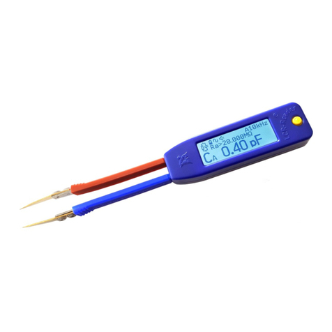
Digital Multimeter LCR-Reader-MPA-BT
Bluetooth Data Acquisition Tool
User’s Manual
Version 2.1
Firmware Version 40

©
2020 Siborg Systems Inc Page 2
Contents
1. Introduction...................................................................................................................2
2. System requirements....................................................................................................2
3. Software installation .....................................................................................................2
4. Connection ...................................................................................................................2
5. Buttons on the screen:..................................................................................................3
6. Setting measurement profiles .......................................................................................4
6.2 Single components test mode .................................................................................4
6.2 Multiple Components Test Mode.............................................................................5
6.3 Data Recording. ......................................................................................................5
7. Uninstall software .........................................................................................................5
1. Introduction
The Data Logger for the LCR-Reader-MPA-BT multimeter is an application program that
provides a graphical user interface for controlling test parameters and recording data from
the LCR-Reader-MPA-BT multimeter. You can download it on the website http://www.lcr-
reader.com/downloads/MPA.
2. System requirements
• Operating system: 32bit Windows XP or higher.
• RAM: 512 MB or more.
• Mandatory accessories: USB Bluetooth adapter (LCR-MPA-BTA), Digital Multimeter
LCR-Reader-MPA-BT with Bluetooth module.
• Additional programs: Microsoft Excel 2007 or higher.
3. Software installation
1. Download the program installer from http://www.lcr-reader.com/downloads/MPA
2. Download and run the LCR-MPA-BT_Logger.exe as an Administrator. You have to run
it as Administrator because the Bluetooth dongle drivers need to be copied into the
Windows directory.
3. LCR-MPA-BT Logger program is added to your Start Program list and LCR-
Logger shortcut is created on the desktop
4. Connection
Before starting LCR-MPA-BT Logger, connect the USB Bluetooth adapter to the PC and
turn on LCR-Reader-MPA-BT.
If you start the program first and and only then connect the dongle and turn on the device,
it may not connect. If no connection is established, uncheck ‘Auto’ in the top right corner of
the screen and click ‘Connect’ to the left of the ‘Auto' button to initiate the connection.
Please note: it may need a few Connect and Disconnect clicks to activate the bluetooth
connection.
Once the connection is established the following screen will appear. It has a few sections
playing different roles. The main section of the screen, shown in blue below, presents the
measurement results and test parameters. Some areas of this central section are
“clickable”; when the mouse hovers over a displayed parameter a box around the
parameter appears, left-click may be used to reveal a settings menu allowing to change
the measurement setting.

©
2020 Siborg Systems Inc Page 3
Detailed layout of the clickable parameters is shown below.
5. Buttons on the screen:
1. RLCD: Turns on RLCD regime for measuring LCR and Diodes using AC
2. RD: DC measurement regime for C, R Diodes and LEDs
3. U: AC/DC Voltage regime
4. Brightness: turns on / off the backlight of the LCR-Reader-MPA-BT device screen.
5. Hold: Enables/disables Hold mode.
6. Sound: Turns on/off the sound.
7. Default: Restores Default Settings.
8. Connect/Auto: Automatic or Manual BT connection.
9. Clickable areas: As shown above Primary Parameter, Secondary Parameter, Test
Frequency, Test Signal Level, and Circuit Mode open setting menus

©
2020 Siborg Systems Inc Page 4
6. Setting measurement profiles
This is the most important feature of LCR-MPA-BT Logger. Since components are not
ideal, they exhibit different values at different test conditions, e.g. amplitude of the test
signal or its frequency. Therefore, when testing a component, we must keep in mind what
conditions should be used in every case. LCR-MPA-BT Logger makes it very easy by
allowing to create test profiles and saving them in different files. Every file can be used to
test any number of components with specific test conditions for every one of the
components.
For testing a component, put in the reference component values in the Reference Value
window and select the test parameters using clickable setting parameters as was
described previously. The first number is the record number in the test profile, then the
component name, primary and secondary component value, and in the row above,
primary, and secondary component type and respective tolerances. If you wish to save the
test settings, click on Write to write the settings in the Test Profile.
If you wish to add a new component to the Test Profile, switch
to the Multiple Component mode, input the parameters and
click on Add. The new component will be added to the test
profile above the current record pushing all subsequent
records down. You may also delete a component from the test
profile by clicking on Delete button.
Now the program is ready to start testing. Just connect your component to the test leads
and click on the Start button to the right of the Reference Value window. Measured values
will begin appearing in the rows below. Values fitting in the tolerance range will be shown
in the “Test” column as “Pass” on a green background, otherwise it will be shown as “Fail”
on a red background. If Fail is shown, it also shows what condition was not met, Primary or
Secondary parameter tolerance.
6.2 Single components test mode
In the single component mode, test measurement records are all displayed on the screen
one after another with a Write interval that can be specified in the Output Control section of
the screen. There you may also set the Initial position for the first record. On the right from
the Start/Stop button you can see self explanatory “Export to
Excel” and “Clear” buttons. Measurements start when you
press the Start button and stop when you press the Stop
button. Alternatively, you may press Space Bar on the
keyboard to make a single measurement.

©
2020 Siborg Systems Inc Page 5
6.2 Multiple Components Test Mode
In the Multi Component Test mode all the components included in the current Test Profile
are shown on the screen. In this mode, measurements results are recorded in the same
line corresponding to the tested component overwriting the previous result. Same as for
the Single Component test mode, measurement starts when you click on the Start button
and stop when you click on the Stop button. Alternatively, you may use Space Bar to make
a single measurement.
6.3 Data Exporting
To transfer data from the screen table to the EXCEL file, click the button Export to Excel
file. The Clear button - clears the table.
7. Uninstall software
Go to the Windows Control Panel, Select Programs and components, Select LCR-MPA-
BT-Logger and click the Uninstall.
Table of contents
Other Siborg Multimeter manuals
