SICK IVP Ranger E/D User manual
Ranger E/D
Operating Instructions
OPERATING INSTRUCTIONS

© SICK IVP 2006-11-16
All rights reserved
8011731
Subject to change without prior notice.
Please read the complete manual before attempting to operate your Ranger.
WARNING
Turn off power before connecting
Never connect any signals while the Ranger unit is powered.
Never connect a powered Ranger E/D Connection terminal or powered I/O signals to a
Ranger.
Do not open the Ranger
The Ranger unit should not be opened. The Ranger contains no user serviceable parts
inside.
Safety Hints if used with laser equipment
Ranger is often supposed to be used in combination with laser products.
The user is responsible to comply with all laser safety requirements according to the laser
safety standards IEC 60825 – 1 (2001-08) and 21 CFR 1040.10/11 (CDRH) respectively.
Please read the chapter “Laser Safety” in Appendix B carefully.
Turn off the laser power before maintenance
If the Ranger is used with a laser (accessory), the power to the laser must be turned off
before any maintenance is performed. Failure to turn this power off when maintaining the
unit may result in hazardous radiation exposure.
ISM Radio Frequency Classification - EN55011 - Group1, Class A
Class A equipment is intended for use in an industrial environment. There may be potential
difficulties in ensuring electromagnetic compatibility in other environments, due to con-
ducted as well as radiated disturbances.
Explanations:
Group1 – ISM equipment (ISM = Industrial, Scientific and Medical)
Group 1 contains all ISM equipment in which there is intentionally generated and/or used
conductively coupled radio-frequency energy which is necessary for the internal function-
ing of the equipment itself.
Class A equipment is equipment suitable for use in all establishments other than domestic
and those directly connected to a low voltage power supply network which supplies build-
ings used for domestic purposes.
Class A equipment shall meet class A limits.
Note: Although class A limits have been derived for industrial and commercial establish-
ments, administrations may allow, with whatever additional measures are necessary, the
installation and use of class A ISM equipment in a domestic establishment or in an estab-
lishment connected directly to domestic electricity power supplies.
Please read and follow ALL Warning statements throughout this manual.
Windows and Visual Studio are registered trademarks of Microsoft Corporation.
All other mentioned trademarks or registered trademarks are the trademarks or registered trademarks of their
respective owner.
a

Operating Instructions
Ranger E/D
8011731 SICK IVP • Industrial Sensors • www.sickivp.com • All rights reserved 3
Contents
Contents
1Introduction ................................................................................................................................... 4
2Installation Guide .......................................................................................................................... 6
2.1 Preparations ............................................................................................................................ 6
2.1.1 PC Hardware Requirements ...................................................................................... 7
2.1.2 Preparing the Network............................................................................................... 7
2.2 Mounting the Ranger............................................................................................................... 8
2.3 Connecting the Ranger............................................................................................................ 9
2.4 Installing Ranger Software ....................................................................................................10
2.5 Getting an Image from the Ranger .......................................................................................11
2.6 Maintenance..........................................................................................................................12
2.7 Service ..................................................................................................................................12
3Overview.......................................................................................................................................13
3.1 Measuring with the Ranger ...................................................................................................13
3.2 Mounting the Ranger.............................................................................................................14
3.3 Configuring the Ranger..........................................................................................................15
3.3.1 Ranger Studio ..........................................................................................................15
3.3.2 Measurement Methods ...........................................................................................16
3.4 Developing Applications ........................................................................................................20
3.5 Triggering ...............................................................................................................................21
4Hardware Description .................................................................................................................22
4.1 Sensor ..................................................................................................................................22
4.1.1 Light Sensitivity ........................................................................................................22
4.2 Electrical Connections........................................................................................................... 23
4.3 Technical Data ....................................................................................................................... 25
4.4 Dimensional Drawing ............................................................................................................26
Appendix ............................................................................................................................................27
ARanger E and D Models.........................................................................................................27
BLaser Safety ...........................................................................................................................28
CRecommended Network Cards .............................................................................................29
DRecommended Switches....................................................................................................... 30
EiCon Device Configuration.....................................................................................................30
FConnecting Encoders.............................................................................................................31
GRanger E/D Power-I/O terminal ............................................................................................33
HLaser Safety Key Box (ICT-B) ................................................................................................. 35

Chapter 1Operating Instructions
Ranger E/D
4SICK IVP • Industrial Sensors • www.sickivp.com • All rights reserved 8011731
Introduction
1Introduction
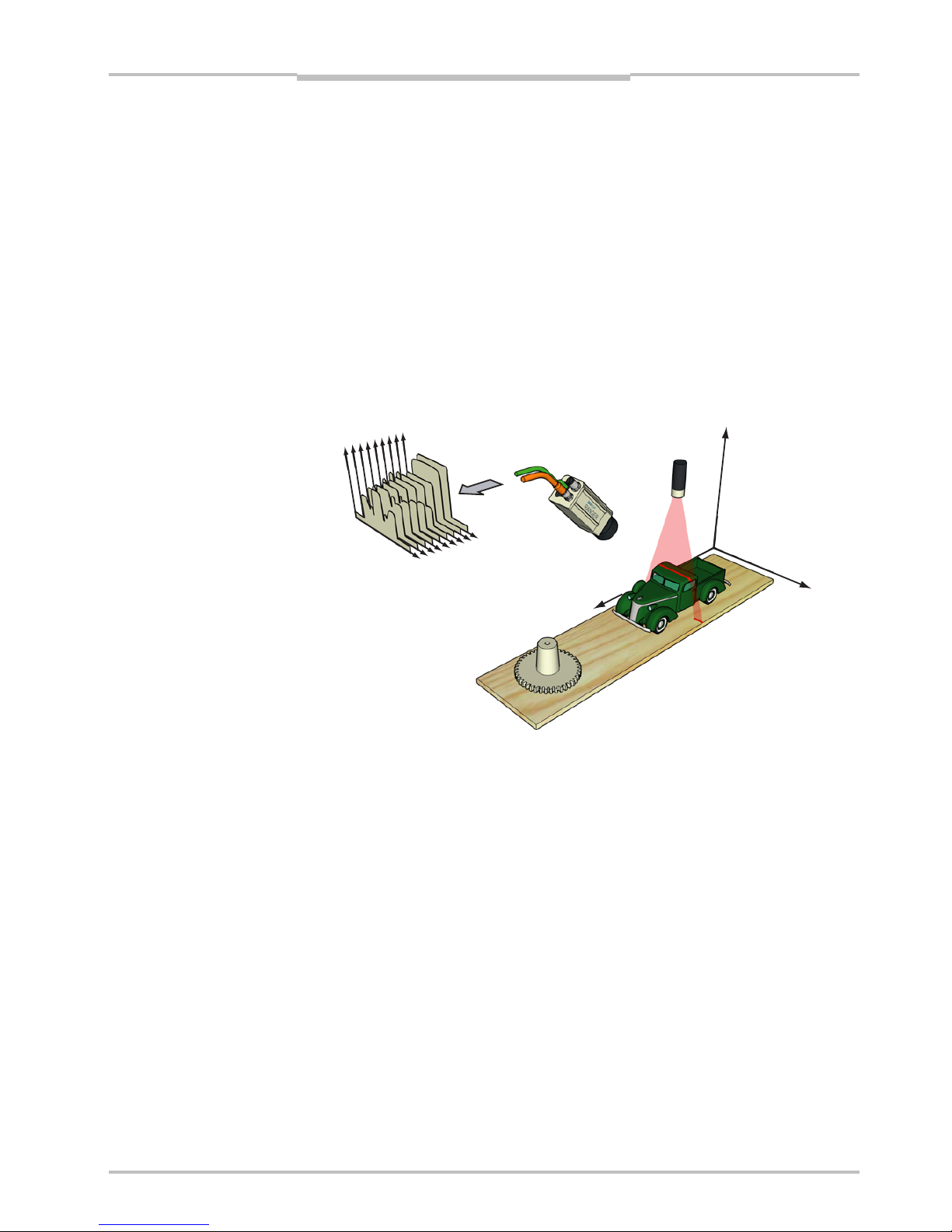
The Ranger is a high-speed 3D camera intended to be the vision component in a machine
vision system. The Ranger makes measurements on the objects that passes in front of the
camera, and sends the measurement results to a PC for further processing. The meas-
urements can be started and stopped from the PC, and triggered by encoders and photo-
electric switches in the vision system.
Figure 1.1 – The Ranger as the vision component in a machine vision system
The main function of the Ranger is to measure 3D shape of objects. Depending on model
and configuration, the Ranger can measure up to 35 000 profiles per second.
In addition to measure 3D – or range – the Ranger can also measure intensity and scatter:
Range measures the 3D shape of the object by the use of laser triangulation. This can
be used for example for generating 3D images of the object, for size rejection
or volume measurement, or for finding defects on the object if it has a well-
known shape.
Intensity measures the light that is reflected by the object. This can be used for example
for inspecting print on objects or detecting defects in the objects’ surface.
Scatter measures how the incoming light is distributed beneath the object’s surface.
This is useful for example for finding the fiber direction in wood or detecting
delamination defects.

Operating Instructions Chapter 1
Ranger E/D
8011731 SICK IVP • Industrial Sensors • www.sickivp.com • All rights reserved 5
Introduction
Figure 1.2 – 3D (left), intensity (top right), and scatter (bottom right) images of a blister
pack with one damaged blister and two empty blisters.
There are three different models of the Ranger available:
Ranger C Connects to the PC via CameraLink.
Ranger E Connects to the PC through a Gigabit Ethernet network.
Ranger D A low-cost, mid-performance version of the Ranger E, suitable for measuring
3D only in applications without high-speed requirements. The Ranger D can
measure up to 1000 profiles per second.
The Ranger C and E models are MultiScan cameras, which mean that they can make
several types of measurements on the object in parallel. This is achieved by applying
different measurement methods to different parts of the sensor.
By selecting appropriate illuminations for the different areas of the measurement scene,
the Ranger can be used for measuring several features of the objects at the very same
time.
Figure 1.3 – Measuring several properties of the objects at once with MultiScan, using
multiple light sources.
Field-of-vie
w
Scatte
r
3D measurement
Grayscale
White light
Lasers

Chapter 2Operating Instructions
Ranger E/D
6SICK IVP • Industrial Sensors • www.sickivp.com • All rights reserved 8011731
Installation Guide
2Installation Guide
2.1 Preparations
The following parts are recommended for getting started with the Ranger:
The Ranger E or D camera
A PC with a network interface card (NIC) that supports Gigabit Ethernet (for information
on requirements, see Appendix)
A Ranger E/D accessory kit:
– A Ranger E/D Power-I/O terminal
– An Ethernet cable for Gigabit Ethernet (5 m)
– A Power IO–Encoder Y-cable (2xM12 female – D-SUB male, 2 m)
– A lens, 25 mm F1.4, C-mount 1” optics
– Camera mounting parts
– A power supply (24 V DC wide range power supply with 1m cable and a standard
power input to support US/Europe cord)
– Operating Instructions (printed)
Ranger E/D Development software CD (including Ranger Studio)
Line-projecting laser, 660 nm
Laser triangulation parts
Figure 2.1 – Ranger E accessory kit
Some of parts listed above are recommended but not required for a working Ranger
system. For a minimal Ranger system the following parts are required:
A Ranger E or D camera
A 24 V DC power supply
A C-mount lens
A laser or other suitable light source
A PC with an Ethernet network interface
An Ethernet cable for camera control and data streaming
A PC application that communicates with the Ranger
Operating Instructions Chapter 2
Ranger E/D
8011731 SICK IVP • Industrial Sensors • www.sickivp.com • All rights reserved 7
Installation Guide
Warning:
Where ever Ranger is used in combination with a laser, all requirements for laser products
and laser systems according to the laser safety standards IEC 60825 – 1 (2001-08) and
21 CFR 1040.10/11 must be fulfilled. Please read chapter ”Laser Safety” in Appendix B
carefully.
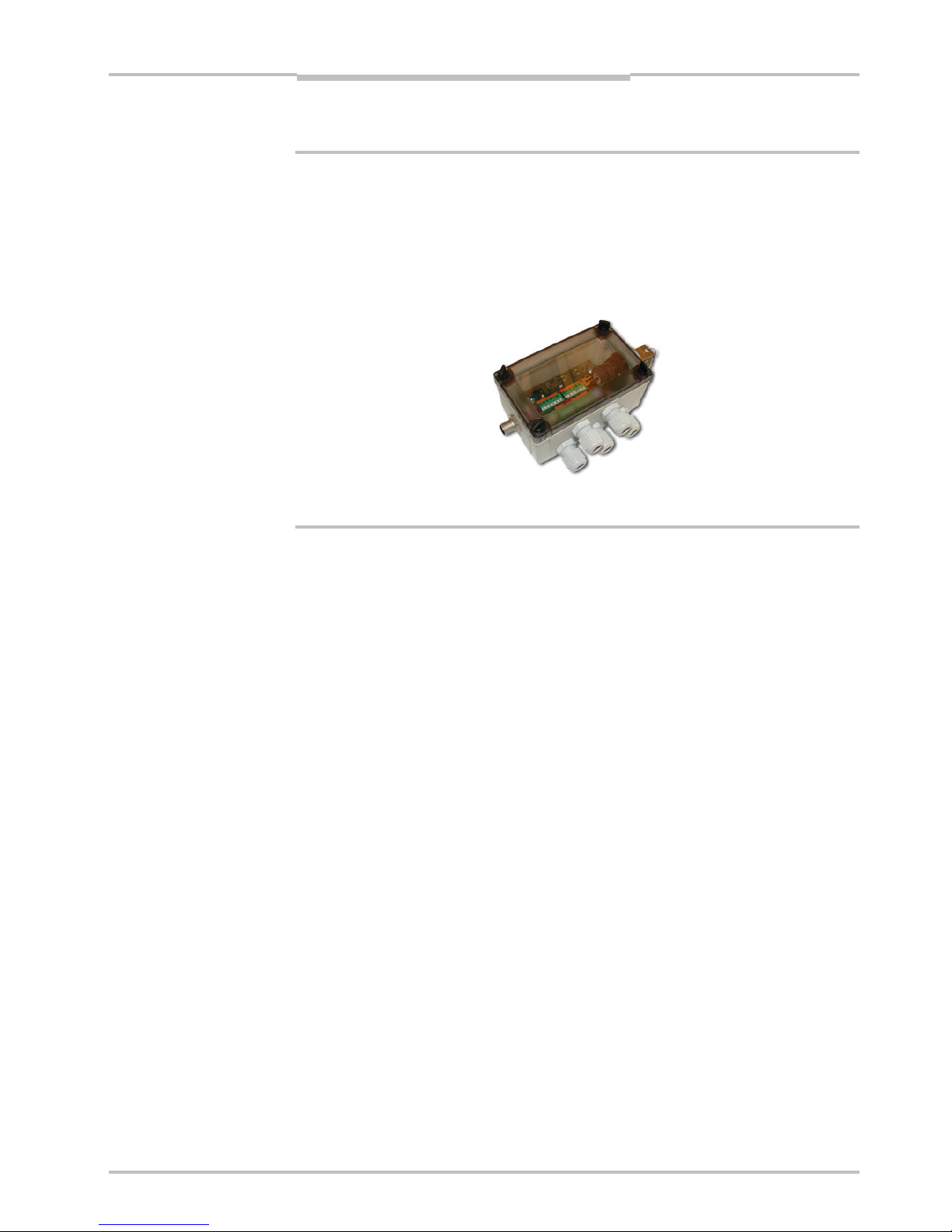
To handle class IIIb/ 3B lasers in an easy way, a laser safety box which provides a key-
actuated master control, a remote interlock connection, a connection for an external
warning lamp and a delayed power-on, is available as accessory.
Figure 2.2 – ICT-B Laser safety box
2.1.1 PC Hardware Requirements
Recommended PC requirements for a Vision system:
AMD Athlon XP 2000+ or Intel P4 2.0 GHz
1024 MB RAM
800 MHz bus speed
1024*768 @ 24 bits of color
Windows XP Pro
A Gigabit Ethernet network interface card
For evaluation purposes, a PC with lower specifications may be sufficient.
2.1.2 Preparing the Network
Due to the large amount of data that the Ranger delivers, it is required to connect them to
the PC using a dedicated Gigabit Ethernet network, without other interfering traffic. If the
PC must be connected to other equipment, for example network printers, the PC should be
equipped with two network interface cards (NIC).
Many PCs today are delivered with a standard NIC for connection to an office network. This
NIC may not support Gigabit Ethernet, and even if it does it may cause performance prob-
lems when used with Rangers. Therefore the PC should always use one of the recom-
mended NIC for Ranger related traffic.
A single Ranger can be connected with or without using a switch. Multiple Rangers are
preferably connected using a switch.
Information about recommended network interface cards and switches can be found in
Appendix C.

Chapter 2Operating Instructions
Ranger E/D
8SICK IVP • Industrial Sensors • www.sickivp.com • All rights reserved 8011731
Installation Guide
Figure 2.3 – Recommended ways of connecting one or more Rangers to a PC
The recommended IP settings:
Device IP address within the range Net mask
PC 192.168.0.1 – 192.168.0.10 255.255.255.0
Camera 192.168.0.11 – 192.168.0.254 255.255.255.0
Each Ranger needs a unique IP address when connected in a network. The Rangers are
delivered with IP addresses, which by default will work in most cases. If necessary, the IP
address of the Ranger can be changed by using the iCon Device Configuration utility.
Information on using iCon Device Configuration can be found in Appendix E.
2.2 Mounting the Ranger
When measuring range, the Ranger is used together with a line-projecting laser line that
illuminates the cross-section of the object to be measured. The Ranger and the laser
should be mounted so that the laser illuminates the object from one direction, and the
Ranger views the object from another direction.
The Ranger and the laser line should be oriented so that the laser line will appear along
the sensor in the Ranger. The Laser line mark on the back of the Ranger indicates in which
direction the Ranger will expect the laser line to be.
Exactly how to mount the Ranger and the laser depends on a whole number of factors. For
more information, see “Mounting Rangers and Lightings” in the Reference manual.
Figure 2.4 – Mounting the Ranger and a laser for measuring range.
PC
Switch
PCPC
Switch
Other network

Operating Instructions Chapter 2
Ranger E/D
8011731 SICK IVP • Industrial Sensors • www.sickivp.com • All rights reserved 9
Installation Guide
For best result it is also important to shield out direct sun light and other disturbing light
from the field of view.
It is also important to select a lens that is suitable for the field-of-view in which the Ranger
should measure. Select a high-quality lens that gives sharp images and low distortion, as
this can be essential for achieving a successful vision application.
The Ranger E has four mounting holes on each side, and two additional holes on the
bottom side near the front. The accuracy in location relative to the sensor is higher for the
two front holes than for the other holes. For drilling instructions, dimensions and further
information, see the Hardware Description on page 22.
2.3 Connecting the Ranger
The following figure shows the position of the connectors on the back of the Ranger. For
more information on wiring and signals on the connectors, see the Hardware Description
on page 22.
encoder
Gigabit Ethernet
data
laser line
link
function on
power
encoder
Gigabit Ethernet
data
link
function on
power
laser line
Figure 2.5 – Connectors on the Ranger E and D respectively.
Warning!
Never connect any signals while the Ranger unit is powered.
Never connect a powered Ranger E/D Power-I/O terminal or powered I/O signals to a
Ranger.
If the laser trigger signal is used for lighting the laser, the laser may become activated as
soon as the Ranger is powered on. Do not look into the laser beam. Avoid looking at the
laser reflection.
Follow the following steps to prepare the Ranger for operation.
1. Ensure that all laser safety requirements are fulfilled for the applicable laser system
according to the standards IEC 60825-1 (2001-08) and 21 CFR 1040.10 / 11
(CDRH). See ”Laser Safety” in Appendix B for details.
2. Remove the protection caps covering the connections for Gigabit Ethernet, Power I/O,
and Encoder connectors.
3. Connect the Ethernet cable to the Gigabit Ethernet connector on the Ranger. Connect
the other end of the Ethernet cable to the Network Interface Card (NIC) in the PC, or to
a Gigabit Ethernet switch.
4. Connect any I/O signals to be used to the Power I/O and the Encoder connector on the
Ranger.
The Ranger E/D Power-I/O terminal is useful for connecting I/O signals to the Ranger.
It offers screw terminals for connecting the signals, and connects to the Ranger with a
Ranger E/D PowerIO-Encoder Y-cable.
5. Connect the unpowered power supply to the Power I/O connector on the Ranger, or to
the power plug on the Ranger E/D Power-I/O terminal.
6. Connect the laser to its power supply. If a stronger laser (class IIIb/3B or higher) is
used, the laser power must be connected through a laser safety box.
7. Switch on the power to the system.
a

Chapter 2Operating Instructions
Ranger E/D
10 SICK IVP • Industrial Sensors • www.sickivp.com • All rights reserved 8011731
Installation Guide
The LEDs on the back of the Ranger will indicate that the Ranger is switched on (on),
connected to the network (link) and possibly sending data over the network (data).
For more information on how to connect I/O signals to the Ranger, see the following
sections:
Hardware Description on page 22
Connecting Encoder on page 31
Ranger E/D Power-I/O terminal on page 33
Figure 2.6 – Connecting the Ranger E and Ranger D
2.4 Installing Ranger Software
The installation program on the Ranger E/D Development software CD will install the
following items on the PC:
Ranger Studio
Ranger SDK, including the iCon APIs
Example programs
Reference Manual
Optional high-performance Ethernet drivers, for lower CPU load at high data rates
To install the Ranger E/D Development software (including Ranger Studio), insert the CD in
the PC and go through the Setup Wizard. The wizard starts automatically when the CD is
inserted. If the installation does not start automatically, double-click on setup.exe on
the CD.
For more detailed information on the installation, see the file releasenotes.txt on
the CD.
Note: You must have administrator privileges on the PC to install the Ranger E/D devel-
opment software.
24 V DC
Ranger E/D
PowerIO-Encoder
Y-cable
I/O signals
24 V DC
Power supply
Gigabit Ethernet
cable
Ranger E/D
Power-I/O terminal
ICT-B Laser
s
afety bo
x
Operating Instructions Chapter 2
Ranger E/D
8011731 SICK IVP • Industrial Sensors • www.sickivp.com • All rights reserved 11
Installation Guide
Follow the instructions in the Wizard and go through the following steps:
1. Click Next to continue from the Welcome page.
2. Select set-up type and click Next.
3. Click Install to begin the installation.
4. Follow the instructions given by the installation program.
5. Click Finish.
Ranger Studio and all other files for development purposes are installed in
/SICKIVP/3DCameras/
2.5 Getting an Image from the Ranger
In order to verify that the installation is correct, follow these steps to receive an image
from the Ranger:
6. Make sure the PC is connected to the Ranger and Ranger Studio is installed on the
PC.
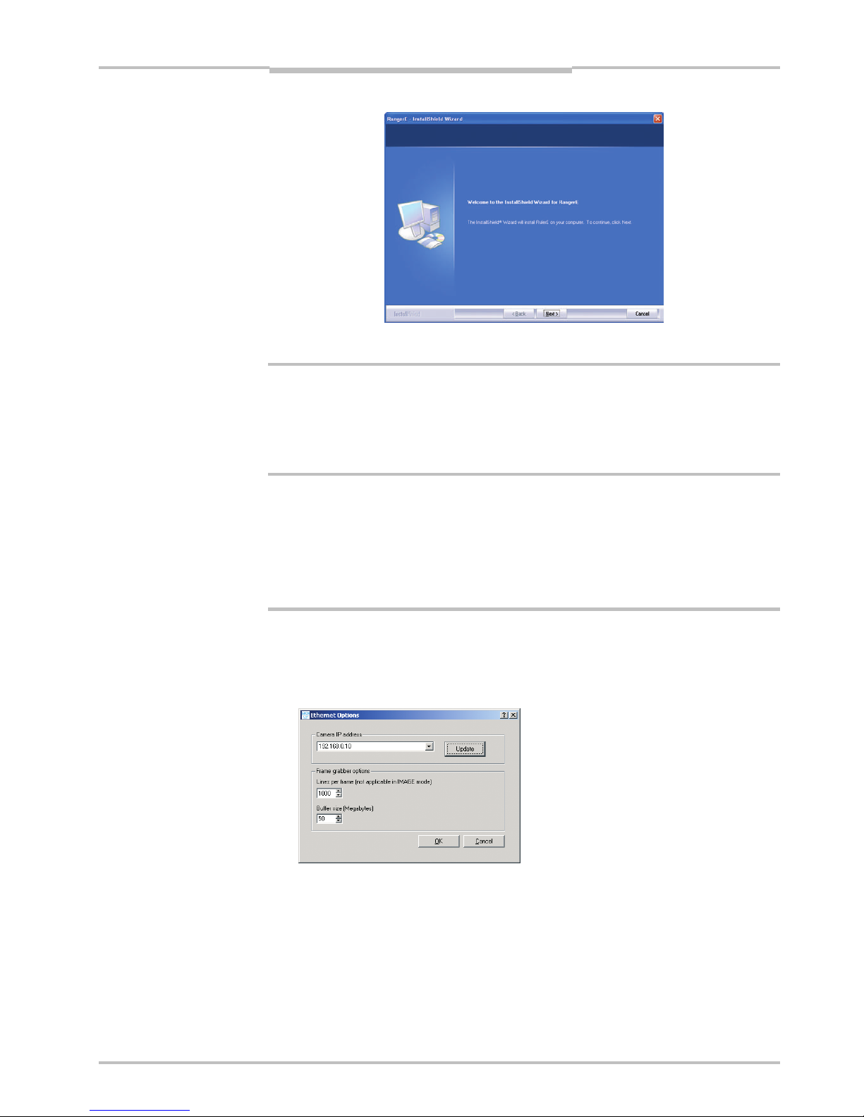
7. Start Ranger Studio.
8. Choose Options ÆOptions from the Ranger Studio menu bar.
The following dialog box is displayed:
9. Fill in the Camera IP address, or select it from the menu, and click OK.
If the Ranger’s IP address is missing in the menu, use the Update button.
Updating the menu may take approximately 15 seconds. You also need to have ad-
ministrator privileges on the PC for the menu to be updated properly.
If you still can not see the Ranger’s IP address, use the iCon Device Configuration util-
ity, which can be launched from the Start menu. Information on using iCon Device
Configuration can be found in Appendix E.
Chapter 2Operating Instructions
Ranger E/D
12 SICK IVP • Industrial Sensors • www.sickivp.com • All rights reserved 8011731
Installation Guide
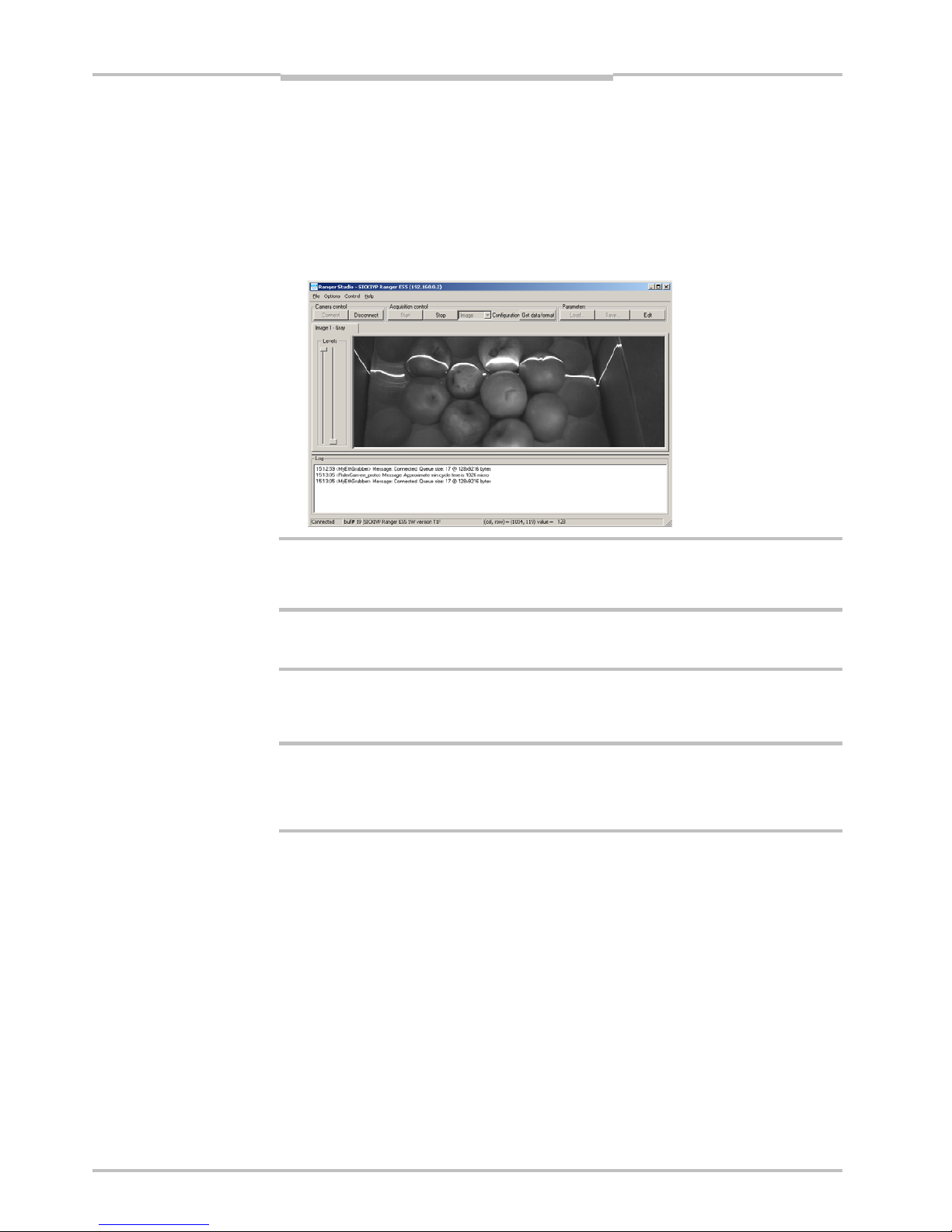
10. Click Connect on the toolbar in Ranger Studio.
The status bar at the bottom of the Ranger Studio main window shows the camera
type and version. The same message is also written in the log.
11. Choose Image from the Configuration menu.
The main window contains one visualization tab, but which is still empty.
12. Click Start to start the acquisition.
The visualization tab shows a live 2D view from the Ranger. If an object is present un-
der a laser line, the projected laser line is also seen in the view.
The Image mode is very useful when it comes to adjusting the exposure time and to decide
the region of interest. More information on how to use the visualization window can be
found in Ranger Studio chapter.
13. When you are ready click Stop to stop the acquisition.
14. Click Disconnect to shut down the conection to the Ranger.
2.6 Maintenance
Warning
If the Ranger is used with a laser, the power to the laser must be turned off before any
maintenance is performed. Failure to turn the power off when maintaining the unit may
result in hazardous radiation exposure.
Check screw connections and connectors at regular intervals.
Clean the housing with a soft cloth, dry or dampened with a mild water diluted cleaning
agent without powder additives.
2.7 Service
The Ranger contains no user serviceable parts inside.
In case of unit failure contact SICK IVP or an SICK IVP representative that delivered the
unit for further instructions.
a
Operating Instructions Chapter 3
Ranger E/D
8011731 SICK IVP • Industrial Sensors • www.sickivp.com • All rights reserved 13
Overview
3Overview
3.1 Measuring with the Ranger
Each time the Ranger makes a measurement, it measures along a cross-section of the
object in front of it. The result of a measurement is a profile, containing one value for each
measured point along the cross-section – for example the height of the object along its
width.
For the Ranger to measure an entire object, the object (or the Ranger and illumination)
must be moved so that the Ranger can make a series of measurements along the object.
The result of such a measurement is a collection of profiles, where each profile contains
the measurement of a cross-section at a certain location along the transportation direc-
tion.
Figure 3.1 – Measuring the range of a cross-section of an object.
For some types of measurements, the Ranger will produce more than one profile when
measuring one cross-section. For example, certain types of range measurements will
result in one range profile and one intensity profile, where the intensity profile contains the
reflected intensity at each measured point.
In addition, the Ranger C and E models – being MultiScan cameras –can also make
parallel measurements on the object. This could for example be used for measuring
surface properties of the objects at the same time as the shape. If the Ranger is config-
ured for MulitScan measurements, the Ranger may produce a number of profiles each
time it makes one measurement – including multiple profiles from one cross-section of the
object, as well as profiles from parallel cross-sections.
In this manual, the term scan is sometimes used for the collection of measurements made
by the Ranger at one point in time.
Note that the range measurement values from the Ranger are not calibrated – that is:
Range values (z coordinates) are given as row – or pixel – locations on the sensor.
The location of a point along the cross-section (x coordinate) is given as a number
representing the column on the sensor in which the point was measured.
The location of a point along the transport direction (y coordinate) is represented by for
example the sequence number of the measurement, or the encoder value for when the
scan was made.
Profiles
z
(range)
x
(width)
y
(transport)
Chapter 3Operating Instructions
Ranger E/D
14 SICK IVP • Industrial Sensors • www.sickivp.com • All rights reserved 8011731
Overview
To get calibrated measurements – for example coordinates and heights in millimeters –
you must yourself perform the transformation from sensor coordinates (row, column,
profile id) to world coordinates (x,y,z). This transformation depends on a number of factors,
for example the distance between the Ranger and the object, the angle between the
Ranger and the laser, and properties of the lens.
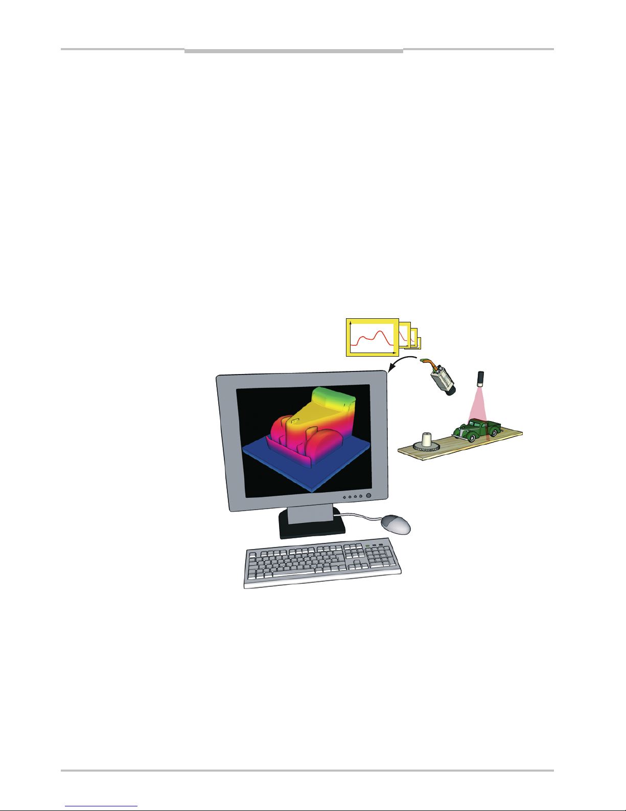
In the machine vision system, the Ranger acts as a data streamer. It is connected to a PC
through either a CameraLink connection (Ranger C) or a Gigabit Ethernet network
(Ranger D & E). The Ranger sends the profiles to the computer, and the computer runs a
custom application that retrieves the profiles and processes the measurement data in
them. This application can for example analyze the data to find defects in the objects and
control a lever that pushes faulty objects to the side.
Before the Ranger can be used in a machine vision system, the following needs to be
done:
Find the right way to mount the Ranger and illuminations.
Configure the Ranger to make the proper measurements.
Write the application that retrieves and processes the profiles sent from the Ranger.
The application is developed in for example Microsoft Visual Studio, using the APIs that
are installed with the Ranger development software.
Figure 3.2 – Profiles are sent from the Ranger to a PC, where they are analyzed by a
custom application.
3.2 Mounting the Ranger
Selecting the right way of illuminating the objects to measure, and finding the right way in
which to mount the Ranger and lightings are usually critical factors for building a vision
system that is efficient and robust.
The Ranger must be able to capture images with good quality of the objects in order to
make proper measurements. Good quality in vision applications usually means that there
is a high contrast between the features that are interesting and those who are not, and
that the exposure of the images does not vary too much over time.
Operating Instructions Chapter 3
Ranger E/D
8011731 SICK IVP • Industrial Sensors • www.sickivp.com • All rights reserved 15
Overview
A basic recommendation is therefore to always eliminate ambient light – for example by
using a cover – and instead use illumination specifically selected for the measurements to
be made.
The geometries of the set-up – that is the placement of the Ranger, the lightings and the
objects in relation to each other – are also important for the quality of the measurement
result. The angles between the Ranger and the lights will affect the type and amount of
light that is measured, and the resolution in range measurements.
Chapter “Mounting Rangers and Lightings” in the Reference manual contains an introduc-
tion to factors to consider when mounting the Ranger and lightings.
3.3 Configuring the Ranger
Before the Ranger can be used in a machine vision application, the Ranger has to be
configured to make the proper measurements, and to deliver the profiles with sufficient
quality and speed. This is usually done by setting up the camera in a production-like
environment and evaluating different ways of mounting, measurement methods and
parameter settings until the result is satisfactory.
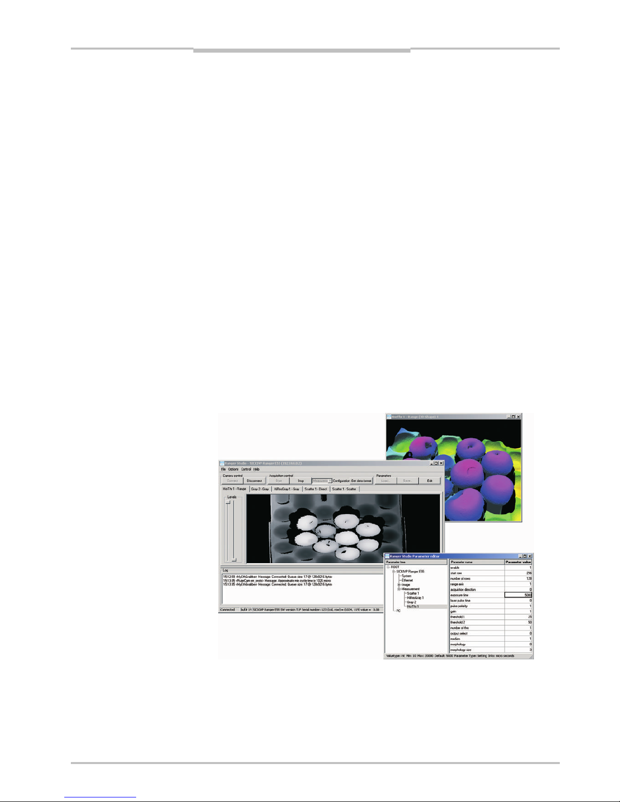
3.3.1 Ranger Studio
The Ranger Studio application – which is a part of the Ranger development software – can
be used for evaluating different set-ups of the camera, and for visualizing the measure-
ments. With Ranger Studio, you can change the settings for the camera and instantly see
how the changes affect the measurement result.
Once the Ranger has been set up to deliver measurement data that meets the require-
ments, the settings can be saved in a parameter file from the Ranger Studio. This parame-
ter file is later used when connecting to the Ranger from the machine vision application.
Figure 3.3 – Configuring the Ranger with Ranger Studio.

Chapter 3Operating Instructions
Ranger E/D
16 SICK IVP • Industrial Sensors • www.sickivp.com • All rights reserved 8011731
Overview
3.3.2 Measurement Methods
One part of configuring the Ranger is selecting which measurement method to use for
measuring. The Ranger has a number of built-in measurement methods – or components
– to choose from.
Which component to use is of course depending on what to measure – range, intensity or
scatter – but also on the following factors:
Required speed and resolution of the measurements
Characteristics of the objects to measure
Conditions in the environment
The MultiScan feature of the Ranger C and E models means that different components can
be applied on different areas of the sensor. These components will then be measuring
simultaneously.
For each component there is a number of settings – parameters – that can be used for
fine-tuning the quality and performance of the measurements. These parameters specifies
for example exposure time and which part of the sensor to use (Region-of-interest, ROI).
Range Components
The Range components are used for making 3D measurement of objects.
The Ranger uses laser triangulation when measuring range, which means that the object is
illuminated with a laser line from one direction, and the Ranger is viewing the object from
another direction. The laser line shows up as a cross section of the object on Ranger’s
sensor, and the Ranger determines the height of each point of the cross-section by locat-
ing the vertical location of the laser line.
The Ranger and the laser line should be oriented so that the laser line will appear along
the sensor in the Ranger. The laser line indicator on the back of the Ranger indicates in
which direction the Ranger expects the laser line to be oriented.
FIgure 3.4 – Laser triangulation
Ranger C and E models have four different components for measuring range, the Ranger D
has one component. They differ in which method is used for locating the laser line:
Horizontal threshold Fast method, using one or two intensity thresholds.
Horizontal max Uses the maximum intensity.
Horizontal max and threshold Uses one intensity threshold.
High-resolution 3D Measures with higher resolution, using an algorithm
similar to calculating the center-of-gravity of the inten-
sity. This is the only component available in Ranger D
cameras.
Sensor image
Laser line
Laser line indicator

Operating Instructions Chapter 3
Ranger E/D
8011731 SICK IVP • Industrial Sensors • www.sickivp.com • All rights reserved 17
Overview
For each measured point, the range value that the Ranger returns represents the number
of rows – or vertical pixels – from the bottom or top of the ROI to where it detected the
laser line.
If the Ranger was unable to locate the laser line for a point – for example due to insuffi-
cient exposure, that the laser line was hidden from view, or that the laser line appeared
outside of the ROI – the Ranger will return the value 0. This is usually referred to as miss-
ing data.
In addition to the range values, all components except Horizontal threshold also deliver
intensity values for the measured points along the laser line. The intensity values are the
maximum intensity in each column of the sensor, which – in the normal case – is the
intensity of the reflected laser line.
Figure 3.5 – Different methods for determining the range by analyzing the light intensity
in each column of the sensor image:
Threshold determines the range by locating intensities above a certain level,
while Max locates the maximum intensity in each column.
The resolution in the measurements depends on which component that is used. For
example the Horizontal max and threshold method returns the location of the laser line
with ½ pixel resolution, while the High-res 3D method has a resolution of 1
/16th of a pixel.
Note that the actual range values from the Ranger depends on the used resolution – for
example if the Ranger is configured to measure with ½ pixel resolution, the returned range
values are the number of ½-pixels from the bottom or top of the ROI.
Besides the measurement method, the resolution in the measurements depends on how
the Ranger and the laser are mounted, as well as the distance to the object. For more
information on how the resolution is affected by how the Ranger is mounted, see chapter
“Mounting Rangers and Lightings” in the Reference manual.
Rows
Columns
Intensity
Threshold
Sensor image
Rows
Intensity
Max
Columns
Rows
Threshold Max
Columns
Projected
laser line

Chapter 3Operating Instructions
Ranger E/D
18 SICK IVP • Industrial Sensors • www.sickivp.com • All rights reserved 8011731
Overview
The performance of the Ranger – that is, the maximum number of profiles it can deliver
each second – depends on the chosen measurement method, but also on the height of
the ROI in which to search for the profile. The more rows in the ROI, the longer it takes to
search.
Therefore, one way of increasing the performance of the Ranger is to use a smaller ROI.
Figure 3.6 – A ROI with few rows will be faster to analyze than a ROI with many rows.
Note that the maximum usable profile rate can be limited by the characteristics of the
object’s surface and conditions in the environment.
Intensity Components
The Intensity components are used for measuring light reflected from the object. They can
be used for example for measuring gloss, inspecting the structure of the object surface, or
inspecting print properties. They can also be used for measuring how objects respond to
light of different wavelength, by using for example colored or IR lightings.
There are two different intensity components:
Gray Measures reflected light along one or several rows on the sensor.
HiRes Gray Available in Ranger models C55 and E55. Uses a special row on the
sensor that contains twice as many pixels as the rest of the sensor
(3072 pixels versus 1536 pixels). The profiles delivered by the HiRes
Gray component therefore has double the resolution compared with the
ordinary Gray component.
Figure 3.7 – Grayscale (left) and gloss (right) images of a CD. Both the text and the crack
are present in both images, but the text is easier to detect in the left image
while the crack is easier to detect in the right.
Some of the range components also deliver intensity measurements. The difference
between using these components and using the Gray or High-res Gray component is that
the Gray and Hi-res Gray components measure the intensity on the same rows for every
column on the sensor, whereas the range components measure the intensity along the
triangulation laser line, which may be located on different sensor rows for each column.

Operating Instructions Chapter 3
Ranger E/D
8011731 SICK IVP • Industrial Sensors • www.sickivp.com • All rights reserved 19
Overview
Scatter Component
The Scatter component is used for measuring how the light is distributed just below the
surface of the object. This can be used for emphasizing properties that can be hard to
detect in ordinary grayscale images, and is useful for example for detecting knots in wood,
finding delamination defects, or detecting what is just below a semi-transparent surface.
Figure 3.8 – Grayscale (left) and scatter (right) images of wood. The two knots are easy to
detect in the scatter image.
The scatter component measures the intensity along two rows on the sensor, and the
result is two intensity profiles – one that should be the center of the laser line (direct), and
one row a number of rows away from the first row (scatter).
The scatter profile can be used as it is as a measurement on the distribution of the light,
but the result will usually be better if the scatter profile is normalized with the direct pro-
file.
Figure 3.9 – Using scatter to detect delamination defects. Where there are no defects,
very little light is reflected below the surface, resulting in a sharp reflex and
low scatter response. Where there is a defect, the light is scattered in the
gap between the layers, resulting in a wider reflection and thus high scatter
response.
Bubble
Ranger
Laser
Chapter 3Operating Instructions
Ranger E/D
20 SICK IVP • Industrial Sensors • www.sickivp.com • All rights reserved 8011731
Overview
3.4 Developing Applications
Once the Ranger has been configured to deliver the measurement data of the right type
and quality, you need to write an application that takes care of and uses the data. This
application is developed in for example Visual Studio, using one of the APIs that are deliv-
ered with the Ranger.
There are two APIs included with the development software for Ranger: iCon C++ for use
with C++ in Visual Studio .Net 2003/2005, and iCon C for use with C in for example Visual
Studio 6. Both APIs contain the same functions but differ in the syntax.
The APIs handle all of the communication with the Ranger, and contain functions for:
Starting and stopping the Ranger
Retrieving profiles from the Ranger
Changing Ranger configuration
Most of these functions are encapsulated in two classes:
Camera Used for controlling the Ranger.
FrameGrabber Collects the measurement data from the Ranger.
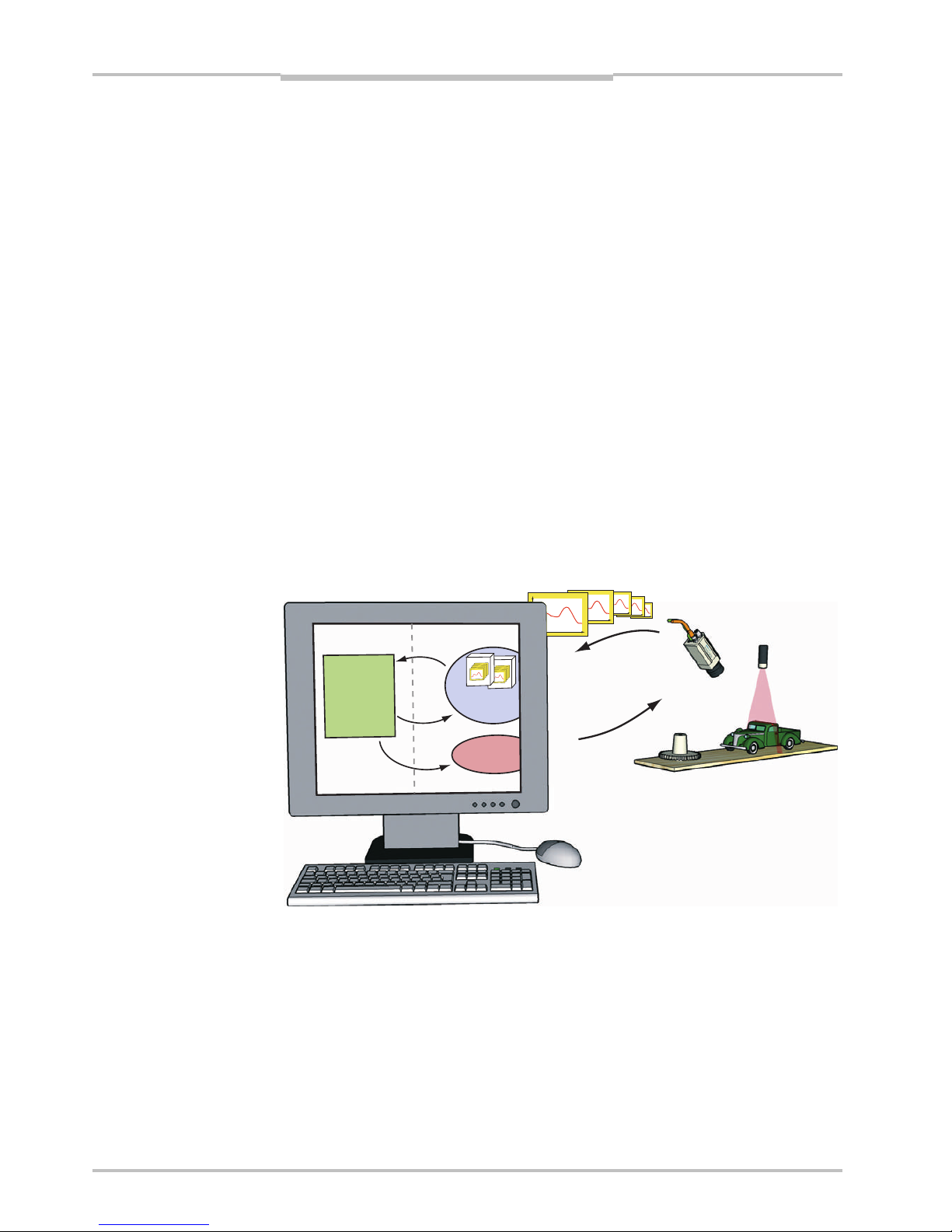
Your application establishes contact with the Ranger camera by creating a Camera object.
It then creates a FrameGrabber object to set up the PC for collecting the measurement
data sent from the Ranger. When your application needs measurement data, it retrieves it
from the FrameGrabber object.
Figure 3.10 – All communication with the Ranger is handled by the API.
When the Ranger is measuring, it will send a profile to the PC as soon as it has finished
measuring a cross-section. The FrameGrabber collects the profiles and puts them in
buffers – buffers that your application then retrieves from the FrameGrabber. Your applica-
tion can specify the size of the buffers, and it is possible to set the buffer size to 1 in order
to receive one profile at a time. However, this will also add overhead to the application,
and put extra load on the CPU.
Profiles
Control
iCon API
Application
Request
Buffers
Control
Camera
Frame
Grabber
This manual suits for next models
2
Table of contents


