Sidewinder 7000 ESP User manual

7000 ESP
Installation Guide
© 2001 Directed Electronics, Inc. Vista, CA N381 5-01
Rev. M 1.0
®

2© 2001 Directed Electronics, Inc. Vista, CA
table of contents
Primary Harness (H1), 12-Pin Connector . . . . . 3
Primary Harness Wiring Diagram . . . . . . . . . 3
Primary Harness Wiring Guide . . . . . . . . . . . 3
Relay Harness (H2), 8-Pin Connector . . . . . . . 8
Relay Harness Wiring Diagram . . . . . . . . . . . 8
Relay Harness Wiring Guide. . . . . . . . . . . . . 8
Wiring the Door Lock System . . . . . . . . . . . . . 9
Identifying the Door Lock System . . . . . . . . 9
At the Switch. . . . . . . . . . . . . . . . . . . . . 10
Type A: Positive-Triggered, Relay Driven
Systems . . . . . . . . . . . . . . . . . . . . . . . . 10
Type B: Negative-Triggered, Relay Driven
Systems . . . . . . . . . . . . . . . . . . . . . . . . 11
Type C: Testing Reverse Polarity Systems
Reversing Polarity . . . . . . . . . . . . . . . . . 11
Type D: Adding one or More Aftermarket
Actuators . . . . . . . . . . . . . . . . . . . . . . . 13
Type E: Electrically Activated Vacuum . . . . . 14
Type F: One-Wire System, Cut to Lock,
Ground To Unlock . . . . . . . . . . . . . . . . . . 15
Type G: Positive (+) Multiplex . . . . . . . . . . 15
Type H: Negative (-) Multiplex . . . . . . . . . . 16
Auxiliary Output Harness (H3),
11-Pin Connector . . . . . . . . . . . . . . . . . . . . 18
Auxiliary Output Harness Wiring Diagram . . . 18
Auxiliary Output Harness Wiring Guide. . . . . 18
Driver’s Door Priority Unlock Diagrams. . . . . 20
Plug-In Harnesses. . . . . . . . . . . . . . . . . . . . 21
Super Bright LED, 2-Pin Plug . . . . . . . . . . . 21
Valet/Program Switch, 2-Pin Plug. . . . . . . . 21
Shock Sensor, 4-Pin Plug . . . . . . . . . . . . . 22
Programmer Interface, 3-Pin Plug. . . . . . . . 22
Voice Module Interface, 3-Pin Plug . . . . . . . 22
Internal Programming Jumper . . . . . . . . . . . 23
Light Flash Jumper . . . . . . . . . . . . . . . . . 23
System Features Learn Routine . . . . . . . . . . 24
System Features Menus . . . . . . . . . . . . . . . . 26
Feature Menu 1: Basic Features. . . . . . . . . 26
Feature Menu 2: Advanced Features . . . . . . 26
Feature Menu 3: Auxiliary Channel Outputs. . 27
Feature Descriptions . . . . . . . . . . . . . . . . . 27
Feature Menu 1: Basic Features. . . . . . . . . 27
Feature Menu 2: Advanced Features . . . . . . 29
Feature Menu 3: Auxiliary Channel Outputs. . 30
Transmitter/Receiver Learn Routine . . . . . . . 32
Transmitter Configurations. . . . . . . . . . . . . . 34
Standard Configuration. . . . . . . . . . . . . . . 34
Expanded Configuration . . . . . . . . . . . . . . 34
Multi-Level Security Arming . . . . . . . . . . . . . 35
Transmitter Code Linking . . . . . . . . . . . . . . . 35
Table of Zones. . . . . . . . . . . . . . . . . . . . . . 36
Long-Term Event History . . . . . . . . . . . . . . . 37
Optional Vehicle Recovery System . . . . . . . . 37
Rapid Resume Logic . . . . . . . . . . . . . . . . . . 38
Troubleshooting. . . . . . . . . . . . . . . . . . . . . 39
Wiring Quick Reference Guide . . . . . . . . . . . 40
The Bitwriter®(p/n 998T)
requires chip version 1.4 or
newer to program this unit.

© 2001 Directed Electronics, Inc. Vista, CA 3
primary harness (H1), 12-pin connector
___
___
___
___
___
___
___
___
___
___
___
___
This guide describes in detail the connection of each wire. Also included are possible applications of each wire.
This system was designed with the ultimate in flexibility and security in mind. Many of the wires have more than
one possible function. Please read the instructions carefully to ensure a thorough understanding of this system
and how it operates.
H1/1 ORANGE (-) GROUND-WHEN-ARMED OUTPUT
This wire supplies a (-) ground as long as the system is armed. This output ceases as soon as the system is
disarmed. The orange wire is pre-wired to control the P/N 8618 starter kill relay. It can supply up to 500 mA of
current.
NOTE: If connecting the orange wire to control another module, such as a P/N 529T or P/N 530T
window module, a 1 amp diode (type 1N4004) will be required. (See the following diagram.)
primary harness wiring guide
RED/WHITE OUTPUT OF CHANNEL 2 RELAY #30
RED (+) 12V CONSTANT POWER INPUT
BROWN (+) SIREN OUTPUT
YELLOW (+) SWITCHED IGNITION INPUT, ZONE 8
BLACK (-) CHASSIS GROUND INPUT
VIOLET (+) DOOR TRIGGER INPUT, ZONE 3
BLUE (-) INSTANT TRIGGER INPUT, ZONE 1
GREEN (-) DOOR TRIGGER INPUT, ZONE 3
BLACK/WHITE OUTPUT OF DOMELIGHT SUPERVISION RELAY #30
WHITE/BLUE (-) 200 mA CHANNEL 3 PROGRAMMABLE OUTPUT
WHITE (+/-) SELECTABLE LIGHT FLASH OUTPUT
ORANGE (-) 500 mA GROUND-WHEN-ARMED OUTPUT
H1/1
H1/2
H1/3
H1/4
H1/5
H1/6
H1/7
H1/8
H1/9
H1/10
H1/11
H1/12
primary harness wiring diagram

4© 2001 Directed Electronics, Inc. Vista, CA
IMPORTANT! Never interrupt any wire other than the starter wire.
H1/2 WHITE (+/-) SELECTABLE LIGHT FLASH OUTPUT
As shipped, this wire should be connected to the (+) parking light wire. If the light flash polarity jumper under
the sliding door is moved to the opposite position (see Internal Programming Jumpers section of this guide), this
wire supplies a (-) 200 mA output. This is suitable for driving (-) light control wires in vehicles such as Toyota,
Lexus, BMW, some Mitsubishi, some Mazda, and other model cars.
(+) LIGHT FLASH OUTPUT
(-) LIGHT FLASH OUTPUT
H1/3 WHITE/BLUE (-) 200 mA CHANNEL 3 PROGRAMMABLE OUTPUT
This wire provides a 200 mA (-) output whenever the transmitter button(s) controlling Channel 3 is pressed. This
output can be programmed to provide the following types of output (also see System Features Learn Routine
section of this guide):

© 2001 Directed Electronics, Inc. Vista, CA 5
■A validity output will send a signal as long as the transmission is received.
■A latched output will send a signal continuously when Channel 3 is pressed and will continue until Channel
3 is pressed again.
■Alatched/reset with ignition output functions similarly to the latched output, but will also reset (output
will stop) when the ignition is turned on and then off.
■A 30-second timed output will send a signal for 30 seconds when Channel 3 is pressed. This output can be
shut off during the 30-second period by pressing the Channel 3 transmitter button(s) again.
IMPORTANT! Never use this wire to drive anything but a relay or a low-current input! This
transistorized output can only supply 200 mA, and connecting directly to a solenoid, motor, or other
high-current device will cause the module to fail.
H1/4 BLACK/WHITE HIGH CURRENT OUTPUT FROM ON-BOARD DOMELIGHT SUPERVISION RELAY
Connect this wire directly to the domelight circuit in the vehicle. The on-board relay will drive circuits up to 20
amperes. The polarity of this output is determined by the connection of the input wire (H2/B) in the Door Lock
Harness.
NOTE: If the input wire (H2/B) is not connected, there will be no output on this wire.
H1/5 GREEN (-) DOOR TRIGGER INPUT, ZONE 3
Most vehicles use negative door trigger circuits. Connect the green wire to a wire showing ground when any door
is opened. In vehicles with factory delays on the domelight circuit, there is usually a wire unaffected by the delay
circuitry. This wire will report Zone 3.
H1/6 BLUE (-) INSTANT TRIGGER, ZONE 1
This input will respond to a negative input with an instant trigger. It is ideal for hood and trunk pins and will
report on Zone 1. It can also be used with 506T Glass Breakage Sensor, as well as other DEI single stage sensors.
The H1/6 BLUE instant trigger wire can be used to shunt sensors during operation, using the auxiliary channels.
When any of the auxiliary channels are transmitted, the H1/6 BLUE wire monitors for a ground. If a ground is
detected within 5 seconds of transmission, the sensors and the instant trigger input on the BLUE wire will be
shunted until 5 seconds after the ground is removed. This allows the customer to access the trunk, remote start
the vehicle or roll the windows down without first disarming the alarm. (See Bypassing Sensor Inputs section of
this guide.)

6© 2001 Directed Electronics, Inc. Vista, CA
H1/7 VIOLET (+) DOOR TRIGGER INPUT, ZONE 3
This type of domelight circuit is used in many Ford vehicles. Connect the violet wire to a wire that shows (+)12V
when any door is opened, and ground when the door is closed. This wire will report Zone 3.
H1/8 BLACK (-) CHASSIS GROUND INPUT
Remove any paint and connect this wire to bare metal, preferably with a factory bolt rather than your own screw.
(Screws tend to either strip or loosen with time.) We recommend grounding all your components, including the
siren, to the same point in the vehicle.
H1/9 YELLOW (+) SWITCHED IGNITION INPUT, ZONE 8
Connect this wire to the (+)12V ignition wire. This wire is pre-wired to the starter kill relay and must show (+)12V
with the key in the run position and during cranking. Take great care that this wire cannot be shorted to the
chassis at any point. This wire will report Zone 8.

© 2001 Directed Electronics, Inc. Vista, CA 7
H1/10 BROWN (+) SIREN OUTPUT
Connect this to the red wire of the Revenger siren. Connect the black wire of the siren to (-) chassis ground,
preferably at the same point you connect the control module’s black ground wire.
H1/11 RED (+)12V CONSTANT POWER INPUT
Before connecting this wire, remove the supplied fuse. Connect to the positive battery terminal or to the con-
stant 12V supply to the ignition switch.
NOTE: Always use a fuse within 12 inches of the point you obtain (+)12V. Do not use the 15 amp
fuse in the harness for this purpose. This fuse protects the module itself.
H1/12 RED/WHITE HIGH CURRENT OUTPUT FROM ON-BOARD CHANNEL 2 RELAY
Whenever the button(s) controlling Channel 2 is pressed for 1.5 seconds, the on-board relay is activated and will
stay active as long as the transmission continues. This relay is often used for trunk release. The relay can drive
circuits up to 20 amperes. The polarity of this output is determined by the connection of the input wire (H2/A)
on the Door Lock Harness.
NOTE: If the input wire (H2/A) is not connected, there will be no output from the relay when it is
activated.

8© 2001 Directed Electronics, Inc. Vista, CA
relay harness (H2), 8-pin connector
___
___
___
___
___
___
___
___
*NOTE: VIOLET and VIOLET/BLACK are common at fuse holder.
H2/A RED/WHITE INPUT TO ON-BOARD CHANNEL 2 (TRUNK RELEASE) RELAY
This wire is used to supply voltage to the H1/12 output. If you want a positive output on the H1/12 wire,
connect this wire to (+)12V. Always fuse appropriately. If a negative output is desired, connect the H2/A
red/white wire to chassis ground.
H2/B BLACK/WHITE INPUT TO DOMELIGHT SUPERVISION RELAY
This wire determines what the output polarity of the H1/4 wire will be. If the door pin circuit is negative, connect
to chassis ground. If the doorpin circuit is positive, connect to a fused 12V source.
H2/C, H2/D, H2/E, H2/F, H2/G, AND H2/H POWER DOOR LOCK WIRES
This security system has door lock relays on-board the control module, and can directly interface with most
electric power door lock systems drawing 30 amps or less. It can also drive aftermarket actuators directly.
Some vehicles require that an aftermarket actuator be added to the driver’s door to allow system control. (See
Type D wiring.)
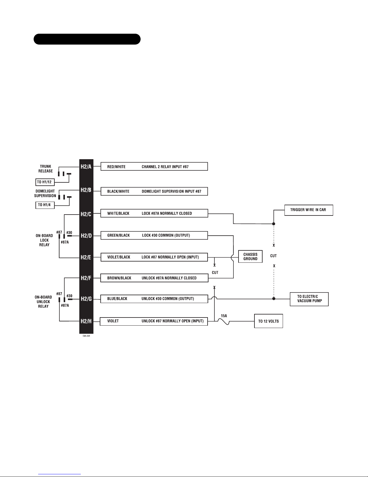
relay harness wiring guide
VIOLET* UNLOCK #87 NORMALLY OPEN (INPUT)
BLUE/BLACK UNLOCK #30 COMMON (OUTPUT)
BROWN/BLACK UNLOCK #87A NORMALLY CLOSED
VIOLET/BLACK* LOCK #87 NORMALLY OPEN (INPUT)
GREEN/BLACK LOCK #30 COMMON (OUTPUT)
WHITE/BLACK LOCK #87A NORMALLY CLOSED
BLACK/WHITE DOMELIGHT SUPERVISION RELAY INPUT #87
RED/WHITE CHANNEL 2 RELAY INPUT #87
H2/A
H2/B
H2/C
H2/D
H2/E
H2/F
H2/G
H2/H
relay harness wiring diagram

© 2001 Directed Electronics, Inc. Vista, CA 9
wiring the door lock system
The easiest way to determine which type of door lock system you are working with is to remove the master locking
switch itself, which is usually on the driver’s door or on the center console. Once you have determined which type
of factory door lock circuit you are working with, and the color codes of the switch wires to be used, you can
usually simplify the installation by locating the same wires in the vehicle’s kick panel. If no central locking switch
is found, the installation may require a door lock actuator.
NOTE: Always retest the wires in the kick panel to be sure they work the same as the wires on the switch.
There are eight common types of door lock circuits:
TYPE A: 3-WIRE (+) PULSE CONTROLLING FACTORY LOCK RELAYS
Most GM, some Ford and Chrysler, 1995 and newer Saturns, some new VW, newer BMW.
TYPE B: 3-WIRE (-) PULSE CONTROLLING FACTORY LOCK RELAYS
Most Asian vehicles, early Saturn, some BMW and Porsche.
TYPE C: DIRECTLY-WIRED REVERSING-POLARITY SWITCHES
The switches are wired directly to the motors. This type of system has no factory relays. Most Fords, many GM
two-doors cars and trucks, many Chryslers.
TYPE D: ADDING ONE OR MORE AFTER-MARKET ACTUATORS
These include slave systems without an actuator in the driver’s door, but with factory actuators in all the other
doors. Type D also includes vehicles without power locks, which are having actuators added. All Saabs before
1994, most Volvo (except 850i), most Subaru, most Isuzu, and many Mazdas. Some mid-eighties Nissans, pre-1985
Mercedes-Benz and Audi.
TYPE E: ELECTRICALLY ACTIVATED VACUUM SYSTEMS
The vehicle must have a vacuum actuator in each door. Make sure that locking the doors from the driver's or pas-
senger side using the key activates all the actuators in the vehicle. This requires a slight modification to the door
lock harness. Mercedes-Benz and Audi 1985 and newer.
TYPE F: ONE-WIRE SYSTEM - CUT TO LOCK, GROUND TO UNLOCK
This system is found in the late-model Nissan Sentra, some Nissan 240SX, and Nissan 300ZX 1992 and later. It is
also found in older Mitsubishis, and some early Mazda MPV’s.
identifying the door lock system

10 © 2001 Directed Electronics, Inc. Vista, CA
TYPE G: (+) MULTIPLEX SYSTEM
This system is most commonly found in Ford, Mazda, Chrysler and GM vehicles. The door lock switch or door key
cylinder may contain either one or two resistors.
TYPE H: (-) MULTIPLEX SYSTEM
The system is most commonly found in Ford, Mazda, Chrysler and GM vehicles. The door lock switch or door key
cylinder may contain either one or two resistors.
■Three-wire switches will have either a constant ground input or a constant (+)12V input, along with the
pulsed lock and unlock outputs to the factory relays.
■Many BMW’s and VW’s have no external switch. The switches are inside the actuator, and instead of pulsing,
the proper wires will switch back and forth from (+)12V to (-) ground as the door locks are operated.
■Direct-wired switches will have a (+) 12V constant input and one or two (-) ground inputs, along with two
output leads going directly to the lock motors.
IMPORTANT! The H2/A and H2/B wires are not required for wiring the door locks. For detailed
wiring instructions for these two wires, refer to the beginning of the Door Lock Harness (H2) Wire
Connection Guide section. Depending on the type of door lock system, there may be additional H2
harness wires that are not used for wiring the door locks.
type A: positive-triggered, relay-driven systems
at the switch

© 2001 Directed Electronics, Inc. Vista, CA 11
IMPORTANT! The H2/A and H2/B wires are not required for wiring the door locks. For detailed
wiring instructions for these two wires, refer to the beginning of the Door Lock Harness (H2) Wire
Connection Guide section. Depending on the type of door lock system, there may be additional H2
harness wires that are not used for wiring the door locks.
Use these instructions if the power door lock switch has four or five heavy-gauge wires. This type of switch has
two outputs that rest at (-) ground.
IMPORTANT! To interface with Type C systems, you must cut two switch leads. The relays must
duplicate the factory door lock switches’ operation. The master switch will have one or two ground
inputs, one (+)12V input, and two switch outputs going directly to the slave switch and through
to the motors. These outputs rest at (-) ground. The lock or unlock wire is switched to (+)12V, while
the other wire is still grounded, thus completing the circuit and powering the motor. This will
disconnect the switch from the motor before supplying the motor with (+)12V, avoiding sending
(+)12V directly to (-) ground.
It is critical to identify the proper wires and locate the master switch to interface properly. Locate wires that
show voltage when the switch is moved to the lock or unlock position. Cut one of these wires and check opera-
tion of the locks from both switches. If one switch loses all operation in both directions then you have cut one
of the correct wires and the switch that is entirely dead is the master switch. If both switches still operate in
any way and one or more door motors have stopped responding entirely, you have cut a motor lead. Reconnect
type C: reverse polarity systems
type B: negative-triggered, relay-driven systems

12 © 2001 Directed Electronics, Inc. Vista, CA
it and continue to test for another wire. Once both wires have been located and the master switch has been iden-
tified, cut both wires and interface as shown in the following diagram.
WARNING! If these wires are not connected properly, you will send (+)12 volts directly to (-) ground,
possibly damaging the control module or the factory switch.
IMPORTANT! The H2/A and H2/B wires are not required for wiring the door locks. For detailed wiring
instructions for these two wires, refer to the beginning of the Door Lock Harness (H2) Wire Connection
Guide section. Depending on the type of door lock system, there may be additional H2 harness wires
that are not used for wiring the door locks.
H2/C WHITE/BLACK
Once both door lock wires are located and cut, connect the white/black wire to the master switch side of the lock
wire. The master switch side will show (+)12V when the master switch is operated to the lock position and (-)
ground when the master switch is in the middle position.
H2/D GREEN/BLACK
Connect the green/black wire to the other side of the lock wire. This is the motor side of the lock wire and it
goes to the lock motor through the slave switch.
H2/E VIOLET/BLACK
This wire must be connected to a constant (+)12V source. The best connection point for this wire is the constant
(+)12 volt supply for the door lock switch*, or directly to the (+) battery post with a fuse at the battery post.

© 2001 Directed Electronics, Inc. Vista, CA 13
*NOTE: Except in GM cars with retained accessory power (RAP). In these vehicles, the (+)12V feed
to the door lock switches is turned off if the doors are closed for any length of time.
NOTE: Most direct-wired power lock systems require 20-30 amps of current to operate. Connecting
the violet/black wire to a poor source of voltage will prevent the door locks from operating properly.
H2/F BROWN/BLACK
Connect the brown/black wire to the master switch side of the unlock wire. The master switch side will show
(+)12V when the master switch is in the unlock position and (-) ground when the master switch is in the middle
position.
H2/G BLUE/BLACK
Connect the blue/black wire to the other side of the unlock wire.
Vehicles without factory power door locks require the installation of one actuator per door. This requires mounting
the door lock actuator inside the door. Other vehicles may only require one actuator to be installed in the driver's
door if all door locks are operated when the driver's lock is used.
IMPORTANT! The H2/A and H2/B wires are not required for wiring the door locks. For detailed
wiring instructions for these two wires, refer to the beginning of the Door Lock Harness (H2) Wire
Connection Guide section. Depending on the type of door lock system, there may be additional H2
harness wires that are not used for wiring the door locks.
type D: adding one or more after-market actuators
14 © 2001 Directed Electronics, Inc. Vista, CA
This system is found in Mercedes-Benz and Audi 1985 and newer. The door locks are controlled by an electrically
activated vacuum pump. The control wire will show (+) 12V when doors are unlocked and (-) ground when doors
are locked.
NOTE: The system must be programmed for 3.5 sec door lock pulses.
IMPORTANT! The H2/A and H2/B wires are not required for wiring the door locks. For detailed
wiring instructions for these two wires, refer to the beginning of the Door Lock Harness (H2) Wire
Connection Guide section. Depending on the type of door lock system, there may be additional H2
harness wires that are not used for wiring the door locks.
type E: electrically-activated vacuum

© 2001 Directed Electronics, Inc. Vista, CA 15
This system usually requires a negative pulse to unlock, and cutting the wire to lock the door. (In some vehicles,
these wires are reversed.) Type F door locks are used in the late-model Nissan Sentra, some Nissan 240SX, and
Nissan 300ZX 1992 and later. They are also used in some Mazda MPV's.
NOTE: The violet jumper between the #87 lock terminal and the #87 unlock terminal must be cut.
IMPORTANT! The H2/A and H2/B wires are not required for wiring the door locks. For detailed
wiring instructions for these two wires, refer to the beginning of the Door Lock Harness (H2) Wire
Connection Guide section. Depending on the type of door lock system, there may be additional H2
harness wires that are not used for wiring the door locks.
This system is most commonly found in Ford, Mazda, Chrysler and GM vehicles. The door lock switch or door key
cylinder may contain either one or two resistors.
SINGLE-RESISTOR TYPE: If one resistor is used in the door lock switch/key cylinder, the wire will pulse (+)12V
in one direction and less than (+)12V when operated in the opposite direction.
TWO-RESISTOR TYPE: If two resistors are used in the factory door lock switch/key cylinder, the switch/key cylin-
der will read less than (+)12V in both directions.
type G: positive (+) multiplex
type F: one-wire system - cut to lock, ground to unlock

16 © 2001 Directed Electronics, Inc. Vista, CA
DETERMINING THE PROPER RESISTOR VALUES: To determine the resistor values, the door lock switch/key cylinder
must be isolated from the factory door lock system. For testing, use a calibrated digital multimeter that is set to ohms.
IMPORTANT! To ensure an accurate resistance reading, do not touch the resistor or leads during testing.
1. Cut the output wire from the door lock switch/key cylinder in half.
2. Test with the meter from the switch side of the cut door lock switch/key cylinder wire to a reliable constant
(+)12V source. Some good constant (+)12V references are the power input source to the door lock switch/key
cylinder, the ignition switch power wire, or the (+) terminal of the battery.
3. Operate the door lock switch/key cylinder in both directions to determine the resistor values. If the multi-
meter displays zero resistance in one direction, no resistor is needed for that direction.
4. Once the resistor value(s) is determined, refer to the wiring diagram for proper wiring.
IMPORTANT! The H2/A and H2/B wires are not required for wiring the door locks. For detailed
wiring instructions for these two wires, refer to the beginning of the Door Lock Harness (H2) Wire
Connection Guide section. Depending on the type of door lock system, there may be additional H2
harness wires that are not used for wiring the door locks.
The system is most commonly found in Ford, Mazda, Chrysler and GM vehicles. The door lock switch or door key
cylinder may contain either one or two resistors.
type H: negative (-) multiplex

© 2001 Directed Electronics, Inc. Vista, CA 17
SINGLE-RESISTOR TYPE: If one resistor is used in the door lock switch/key cylinder, the wire will pulse ground
in one direction and resistance to ground when operated in the opposite direction.
TWO-RESISTOR TYPE: If two resistors are used in the factory door lock switch/key cylinder, the door lock
switch/key cylinder will read resistance to ground in both directions.
DETERMINING THE PROPER RESISTOR VALUES: To determine the resistor values, the door lock switch/key cylinder
must be isolated from the factory door lock system. For testing, use a calibrated digital multimeter that is set to ohms.
IMPORTANT! To ensure an accurate resistance reading, do not touch the resistor or leads during testing.
1. Cut the output wire from the door lock switch/key cylinder in half.
2. Test with the meter from the switch side of the cut door lock switch/key cylinder wire to a reliable ground
source. Some good ground references are the ground input source to the door lock switch/key cylinder or the
battery ground.
3. Operate the door lock switch/key cylinder in both directions to determine the resistor values. If the multi-
meter displays zero resistance in one direction, no resistor is needed for that direction.
4. Once the resistor value(s) is determined, refer to the wiring diagram for proper wiring.
IMPORTANT! The H2/A and H2/B wires are not required for wiring the door locks. For detailed
wiring instructions for these two wires, refer to the beginning of the Door Lock Harness (H2) Wire
Connection Guide section. Depending on the type of door lock system, there may be additional H2
harness wires that are not used for wiring the door locks.

18 © 2001 Directed Electronics, Inc. Vista, CA
auxiliary output harness (H3), 11-pin connector
___
___
___
___
___
___
___
___
___
___
___
H3/1 GREEN/BROWN (-) MULTIPLEX SENSOR INPUT
This multiplexed input is capable of triggering either the Warn Away response or the triggered sequence. Inputs
that are shorter than 0.8 seconds will only trigger Warn Away. The first stage of DEI dual stage sensors supplies
this type of pulse. Inputs that are longer than 0.8 seconds will trigger the full alarm cycle. The full trigger will
report on Zone 4 and the Warn Away will report on Zone 6.
H3/2 BROWN/BLACK (-) SENSOR SHUNT INPUT
When ground is applied to this wire, all sensors will be bypassed. The only inputs capable of triggering the system
while this wire is grounded are the door trigger and the ignition. After ground is removed, the system will begin
responding to sensors after 5 seconds. During the 5 second recovery period, an input from any sensor will reset
the 5-second recovery timer. This wire can be used to bypass sensors for remote starting, window roll up, etc.
PROGRAMMABLE OUTPUTS
The outputs for Channels 4 (H3/3), 5 (H3/4) and 6 (H3/5) are programmable. Each of the outputs supplies
200 mA of current and cannot directly drive high current circuits. Selectability allows the installer to configure
the system for a wide range of applications. The four types of outputs that are available are:
auxiliary output harness wiring guide
PINK/BLACK (-) DELAYED ACCESSORY OUTPUT
BLACK/WHITE IGNITION LOCK SAFETY INPUT
ORANGE/BLACK (+) GHOST SWITCH INPUT
GREEN (-) 200 mA FACTORY SECURITY DISARM OUTPUT
BLUE (-) 200 mA SECOND UNLOCK/CHANNEL 7
BROWN (-) 200 mA HORN HONK OUTPUT
WHITE/BLACK (-) 200 mA CHANNEL 6 OUTPUT
GRAY/BLACK (-) 200 mA CHANNEL 5 OUTPUT
PURPLE/BLACK (-) 200 mA CHANNEL 4 OUTPUT
BROWN/BLACK (-) SENSOR SHUNT INPUT
GREEN/BROWN (-) SENSOR INPUT MULTIPLEX ZONES 4 AND 6
H3/1
H3/2
H3/3
H3/4
H3/5
H3/6
H3/7
H3/8
H3/9
H3/10
H3/11
auxiliary output harness wiring diagram

© 2001 Directed Electronics, Inc. Vista, CA 19
■Validity: Output that lasts as long as the button is pressed.
■Latched: Output that turns on the first time the button is pressed and turns off the next time the same
button is pressed.
■Latched, reset with ignition: Output that turns on the first time the button is pressed and turns off the next
time the same button is pressed. This output will cease when the ignition is turned on then off.
■Timed: Output that turns on for a selectable amount of time and stays on until the time runs out or the trans-
mitter button is pressed again.
H3/3 PURPLE/BLACK (-) CHANNEL 4 OUTPUT
This output is programmable for a latched, latched/reset with ignition, validity (default), or timed output. The
timed output is programmable for 30, 60, or 90 seconds.
H3/4 GRAY/BLACK (-) CHANNEL 5 OUTPUT
This output is programmable for a latched, latched/reset with ignition, validity (default), or timed output. The
timed output is programmable for 30, 60, or 90 seconds.
H3/5 WHITE/BLACK (-) CHANNEL 6 OUTPUT
This output is programmable for a latched, latched/reset with ignition, validity (default), or timed output. The
timed output is programmable for 5, 10, 20, 25, or 30 seconds. If using the DEI Bitwriter or the Techsoft
Programmer this output can be programmed for 1-90 seconds.
H3/6 BROWN (-) HORN HONK OUTPUT
This wire provides a 200mA output to drive a low current factory horn circuit. The output can be programmed for
a constant or pulsed output to honk the horn during the full trigger sequence. If the horn circuit is high current
or positive, a relay will be required to drive the circuit.
H3/7 BLUE (-) SECOND UNLOCK/CHANNEL SEVEN OUTPUT
This wire will output a one second 200 mA negative pulse if the disarm button is pressed again after disarming,
within 15 seconds. The most common application of this would be the progressive unlocking of the vehicle. For
example, disarming the system would unlock only the driver’s door. Pressing disarm again within 15 seconds will
output a pulse on this wire that would be used to unlock the rest of the doors. In order to do this the on-board
lock relay must be wired into the driver’s door unlock motor lead, as shown in the following diagrams. The wire
usually can be found in the driver’s door boot. Once the on-board relay is wired to the driver’s motor lead, the
blue wire should be treated as a negative pulse unlock output and wired into the switch as usual.
This output can be used even if the customer does not want the progressive unlock feature. It can be used as
an extra channel to trigger anything that the customer wishes to operate immediately after disarm, for example
the window roll down command. Be sure to program the output as a standard channel. See Feature 3-6 in the
Feature Menus section of this guide.

20 © 2001 Directed Electronics, Inc. Vista, CA
DRIVER'S DOOR UNLOCK ONLY (TYPE A)
DRIVER'S DOOR UNLOCK ONLY (TYPE B)
driver’s door priority unlock diagrams
Table of contents
Other Sidewinder Car Alarm manuals


Popular Car Alarm manuals by other brands

AHB
AHB 440021070 instruction manual

Audiovox
Audiovox Prestige APS-15KB owner's manual

Prestige
Prestige 1287181 installation instructions

CrimeStopper
CrimeStopper CS-2004 WDC Installation and operating instructions

CrimeStopper
CrimeStopper SP-402 operating instructions

Code Alarm
Code Alarm Elite CA6155e owner's manual


