Siedle CE 600-01 User manual

Produktinformation
Farb-CCD-Video-Kamera
für Außenmontage
Product information
External colour CCD
video camera for external
mounting
Information produit
Caméra vidéo CCD
couleur pour montage
en extérieur
Opuscolo informativo
sulprodotto
Telecamera CCD a colori
per montaggio all’esterno
Productinformatie
Kleuren-CCD-Video-
Camera voor buitenmon-
tage
Produktinformation
CCD-farvevideokamera til
udendørs montage
Produktinformation
Färg-CCD-videokamera
för utomhusmontering
Información de producto
Videocámara CCD de color
para montaje exterior
Informacja o produkcie
Kolorowa kamera wideo
CCD do instalacji na
zewnątrz
Информация о продуктах
Цветная видеокамера с
формирователем виде-
осигналов на ПЗС, для
наружного монтажа
CE 600-01

2
g
m
l
h
i
a
b
c
j
k
d
e
f
1
2
3
4
5
OSD
Control
Video
SUB-OUT
6
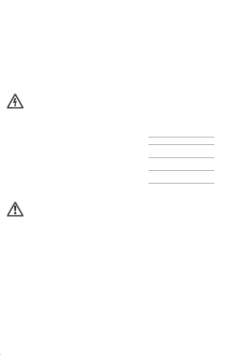
80° 80° 90°
±90°
3
4
Zoom und Fokus einstellen
Zoom und Fokus können direkt an
der Kamera eingestellt werden.
Weitere Einstellungen
6 OSD-Abdeckung abnehmen, dar-
unter bendet sich der Joystick zur
Steuerung der Einstellungen.
Um die Einstellungen vorzunehmen,
muss das Videosignal der Kamera
an einem Monitor über den Video
SUB-OUT Ausgang angeschlossen
werden. Auf dem Monitor ist das
Menü der Kamera zu sehen. Die ein-
stellbaren Menüpunkte sind auf den
nächsten Seiten beschrieben.
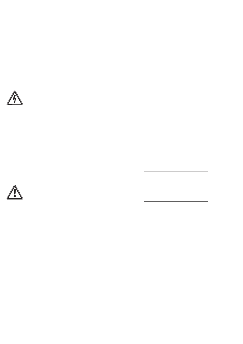
Klemmenbelegung
+, – Versorgungsspannung
20–50VDC
L/S Koaxanschluss
L=Leiter, S=Schirm
RS485+,
RS485–
Datenleitung
Technische Daten
Farbsystem: PAL
Bildaufnehmer: CCD-Sensor1/3"
976x582Pixel
Auösung: 750TV-Linien
Objektiv: 2,8–12mm
Verstellbereich mechanisch:
160°horizontal/ 180°vertikal
Dauerbetrieb: geeignet
Videosausgang: 1Vss an 75Ohm
Betriebsspannung: 20–50VDC
Betriebsstrom: max.250mA
Schutzart: IP67
Umgebungstemperatur:
–20°Cbis+50°C
Abmessungen (mm) BxHxT:
75,3x76x218,5
Pegehinweise
Reinigen Sie die Kamerahaube mit
einem mit milder Seifenlösung ange-
feuchteten, weichen, kratzfreiem
Tuch (z.B. Brillenputztuch, Möbel-
poliertuch o. ä.). Damit keine Flecken
oder Verfärbungen entstehen, sollte
das Pegemittel rückstandslos abge-
wischt werden.
Deutsch
Anwendung
Farb-CCD-Video-Kamera für Außen-
montage mit automatischer Tag-/
Nachtumschaltung (True Day/Night)
und integrierter Infrarotbeleuchtung.
Erfassungswinkel horizontal:
ca.81,2°–22,5°
Elektrische Spannung
Einbau, Montage und Service-
arbeiten elektrischer Geräte dürfen
ausschließlich durch eine Elektro-
Fachkraft erfolgen.
• Bitte lesen Sie diese Produktinfor-
mation, bevor Sie die Kamera in
Betrieb nehmen.
• Betreiben Sie die Kamera nicht
außerhalb der angegebenen
Temperatur-, Feuchtigkeits- oder
Spannungsgrenzwerte.
• Bei der Verlegung der Anschluss-
kabel ist darauf zu achten, dass
diese nicht belastet, geknickt oder
beschädigt werden.
Folgende Einbausituationen müssen
unbedingt vermieden werden:
• direktes Gegenlicht
• direkte Sonneneinstrahlung
• Bildhintergrund mit großer
Helligkeit
• stark reektierende Wände auf
der gegenüberliegenden Seite der
Türstation
• Leuchten bzw. direkte Lichtquellen
Lieferumfang
• CE600-…
• „Easy Bracket“-Halterung
• 4 Kreuzschlitzschrauben 5 x 30
• 4 Dübel D = 6
• 4 Inbusschrauben M4 x 13
• Inbusschlüssel Größe 3
• Video SUB-OUT Kabel
• Anschlussstecker
• diese Produktinformation
1 Produktdetails
a Gehäuse
b Infrarotbeleuchtung
c Objektiv-Scheibe
d Bohrung für Montage
e Anschlusskabel
f Wandarm
g Montagesockel
h „Easy Bracket“-Verriegelung
i OSD-Abdeckung
j Fokus Einstellung
k Zoom Einstellung
l „Easy Bracket“-Haken
m Kabelauslass
Sicherheitshinweise
• Bei abgedunkelter Umgebung und
direktem Blick in den IR-Scheinwerfer
ist ein Sicherheitsabstand von >1m
zum Scheinwerfer einzuhalten.
• Unsichtbare LED-Strahlung nicht
direkt mit optischen Instrumenten
(z.B. Lupe, Vergrößerungsglas etc.)
betrachten, da sie eine Augen-
gefährdung verursachen kann, LED
Klasse 1M.
Montage
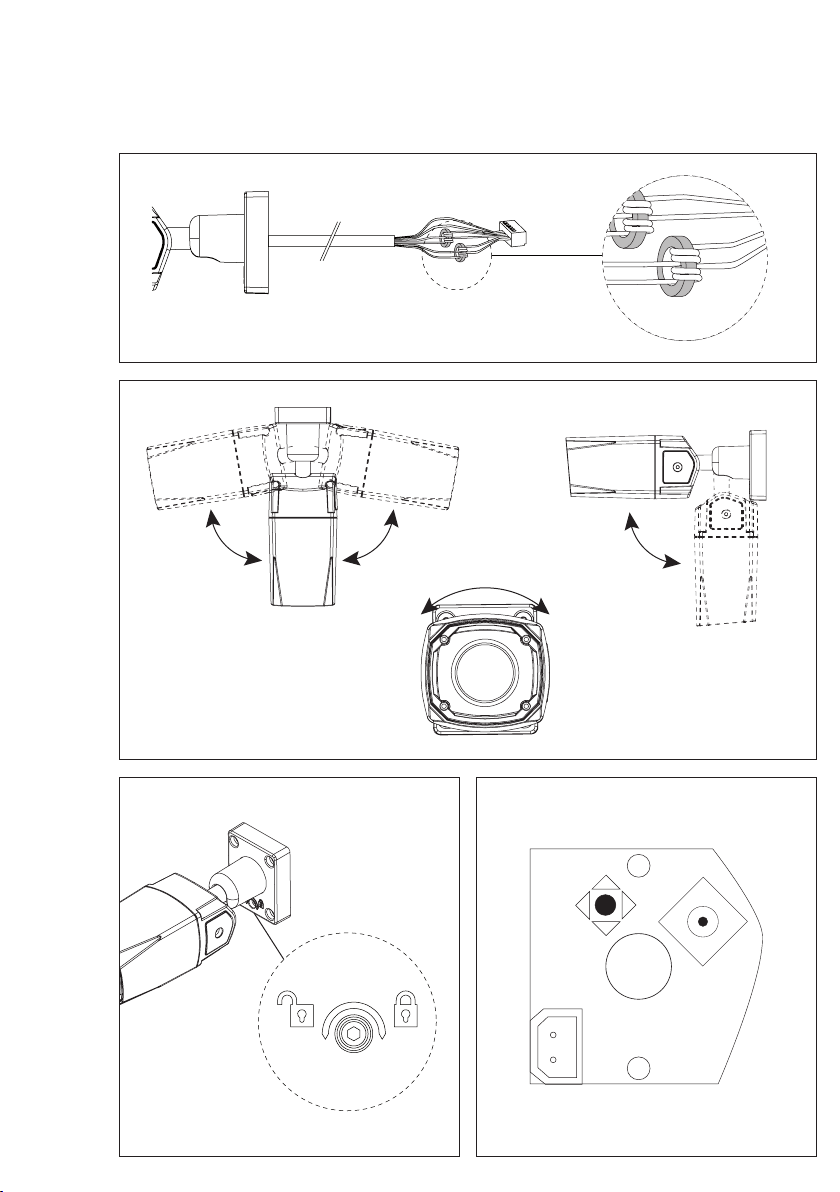
2 „Easy Bracket“-Halterung an der
Wand befestigen; dabei die Einbau-
lage beachten, Haltebügel oben.
3 Beide Ferrit-Ringkerne an den
Anschlussleiter-Paaren (+/–) und
(L/S) dürfen zur Einhaltung des EMV-
konformen Betriebs der externen
Kamera nicht entfernt werden.
Sollten diese zu Montagezwecken
entfernt werden, müssen sie vor
der Inbetriebnahme wieder jeweils
mit zwei Windungen angebracht
werden.
Steckverbindung herstellen und
Haken an der Kamera am Haltebügel
der Wandhalterung einhängen.
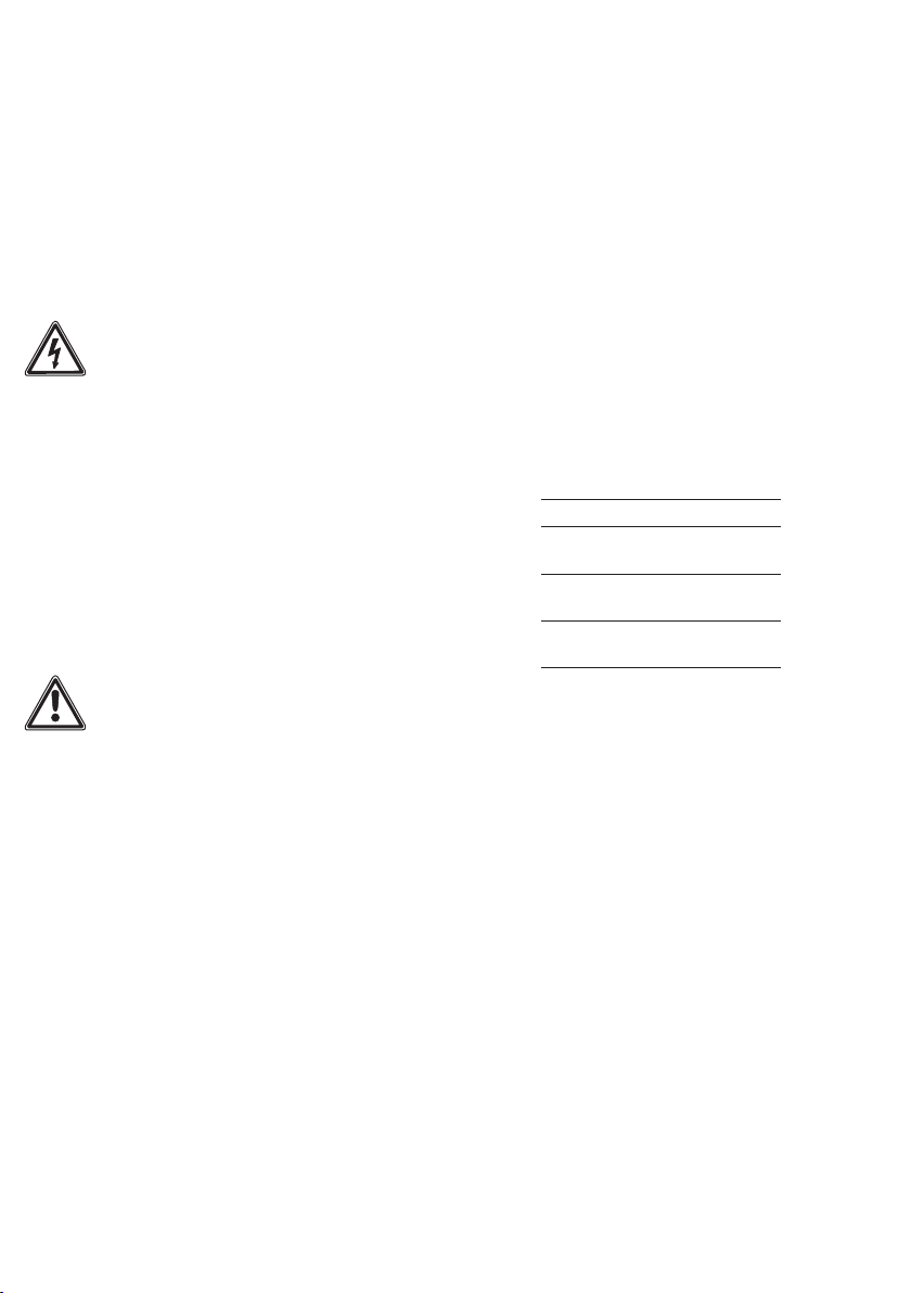
Kamera mit den 4 Inbusschrauben
befestigen.
Die „Easy Bracket“-Halterung ist
nicht für Deckenmontage geeignet,
hier wird der Montagesockel direkt
an die Decke geschraubt.
4 Einstellen des Schwenk- und
Neigungswinkels.
5 Mit dem beiliegendem Inbus-
schlüssel die Kameraeinstellung
xieren.

5
Name Funktion
1 SCENE SELECT Szenenwahl
1.1 SHUTTER/AGC Shutter
1.1.1 AUTO Videopegel Einstellungen automatisch
1.1.2 MANUAL Videopegel Einstellungen manuell
1.1.3 FIX Videopegel Einstellungen fest
1.2 WHITE BAL Weißabgleich
1.2.1 ATW Automatischer Weißabgleich
1.2.1.1 SPEED Einstellung der ATW-Ausgleichsgeschwindigkeit
1.2.1.2 DELAY CNT Einstellung der ATW-Kompensationsperiode
1.2.1.3 ATW FRAME Einstellung des ATW-Bereichs
1.2.1.4 ENVIRONMENT Einstellung der Umgebung
1.3 HLC / BLC Highlight/Backlight Kompensation
1.4 WDR / ATR-EX Gegenlichtkompensation
1.5 DNR Digitale Rauschreduzierung
1.6 DAY/NIGHT Tag & Nacht
1.6.1 AUTO Automatische Tag-/Nachtumschaltung
1.6.1.1 BURST Einstellung des Schwarz/Weiß-Modus
1.6.1.2 CNTL SIGNAL Einstellung des Tag/Nacht-Umschaltpunktes
1.6.1.3 DELAY CNT Einstellung der Tag/Nacht-Umschaltungsverzögerung
1.6.1.4 DAY->NIGHT Einstellung des Schwellenwerts von Tag zu Nacht
1.6.1.5 NIGHT->DAY Einstellung des Schwellenwerts von Nacht zu Tag
1.6.2 DAY Einstellung permanenter Farb-Modus
1.6.3 NIGHT Einstellung permanenter Schwarz/Weiß-Modus
1.7 IR OPTIMIZER IR-Verbesserung (IRO)
1.7.1 MODE Einstellung der Farbsättigung
1.7.2 IR AREA Einstellung des IRO-Bereichs
1.7.3 LEVEL Einstellung der IRO-Stärke
1.7.4 IR LED Einstellung der LED (auto/fest/aus)
1.7.5 COLOR NIGHT Einstellung permanenter Farb-Modus
1.7.6 IR SHADE COMP Einstellung IR-Schatten Kompensation
1.8 LENS SHD COMP Einstellung der Backlight Kompensation
1.9 DEFOG Einstellung der Nebelreduktion
1.10 FLK LESS Einstellung des Flackerfrei-Modus
Kameramenü OSD
Innerhalb des Menüs erfolgt die
Bedienung mit dem Joystick.
Drücken des Joysticks öffnet das
Kameramenü.
• Blättern innerhalb des Menüs mit
Joystick hoch/runter.
• Auswahl einer Funktion durch
Drücken des Joysticks.
• Zurück aus einem Menüpunkt mit
Joystick links.
• Die Ziffern in der Tabelle entspre-
chen der Menüstruktur im OSD und
erleichtern die Navigation.

6
Name Funktion
1.11 ANTI CR Reduziert Flackern von Farben
2PICT ADJUST Bildeinstellung
2.1 BRIGHTNESS Einstellung des Helligkeitspegels
2.2 CONTRAST Einstellung des Kontrasts
2.3 SHARPNESS Einstellung der Bildschärfe
2.4 HUE Einstellung des Farbtons
2.5 COLOR GAIN Einstellung der Farbsättigung
3 EZOOM Einstellung der Maximalvergrößerung des Digital-Zooms
3.1 MAG Einstellung des Vergrößerungsfaktors
3.2 PAN Einstellung der Schwenkung
3.3 TILT Einstellung der Neigung
4 DIS Einstellen der Digitalen Bildstabilisierung
5PRIVACY MASK Geschützte Bereiche
5.1 AREA SEL Einstellung der Maskenbereichsnummer
5.2 DISPLAY Ein- und Ausblenden der Maske
5.3 POSITION Einstellung der Maskenposition
5.4 COLOR Einstellung der Maskenfarbe
5.5 TRANSP Einstellung der Maskentransparenz
5.6 MOSAIC Mosaikanzeige aktivieren/deaktivieren
6 MOTION DET Bewegungserkennung (MD)
6.1 DETECT SENSE Einstellung der MD-Empndlichkeit
6.2 INTERVAL Einstellung der MD-Intervallzeit
6.3 BLOCK DISP Einstellung der Sichtbarkeit der MD-Blöcke
6.4 MASK AREA Einstellung der MD-Blöcke
6.5 MONITOR AREA Einstellung des MD-Bereiches
6.5.1 AREA SEL Einstellung der MD-Position
6.5.2 AREA MODE Aktiviert die MD-Position
6.5.3 TOP/BOTTOM/LEFT/RIGHT Einstellung der Anzeige der MD-Position
7 SYS SETTING Systemeinstellungen
7.1 LENS Objektiv
7.1.1 AUTO Diese Kamera unterstützt nur die Einstellung DC
7.2 FLIP Einstellung der Bildspiegelung
7.3 LCD / CRT Einstellung der Monitorausgabe
7.4 COMMUNICATION Serielle Schnittstelle
7.5 CAMERA ID Einstellung der Kamera-ID
8 LANGUAGE Sprachauswahl
9 VERSION Anzeige der Firmware Version
10 MAINTENANCE Wartung

7
Name Funktion
10.1 W.PIX MASK Weiße Pixel Kompensation (WPK)
10.1.1 MANUAL Einstellung der WPK-Manuell
10.1.2 AUTO Einstellung der WPK-Automatisch
10.1.3 DATA CLEAR Rücksetzen der WPK-Einstellungen
10.2 CAMERA RESET Werkseinstellung
11 EXIT Menü verlassen
8
English
Setting the zoom and focusing
The zoom and focus can be set
directly at the camera.
Other settings
6 Take off the OSD cover, under
which is the joystick for controlling
the settings.
To make the settings, the video
signal of the camera must be con-
nected to a monitor via the video
SUB-OUT output.
The camera menu is shown on the
monitor. The menu items that can be
set are described on the following
pages.
Terminal assignment
+, – Supply voltage
20–50VDC
L/S Coaxial connection
L=lead, S=shield
RS485+,
RS485–
Data lines
Specications
Colour system: PAL
Image pick-up: CCD sensor 1/3"
976x582Pixel
Resolution: 750TV lines
Lens: 2.8–12mm
Mechanical adjustment range:
160°horizontal/180°vertical
Continuous operation: suitable
Video output: 1Vss at 75Ohm
Operating voltage: 20–50VDC
Operating current: max.250mA
Protection system: IP67
Ambient temperature:
–20°Cto+50°C
Dimensions (mm) WxHxD:
75.3x76x218.5
Care instructions
Clean the camera shade using a
soft scratch-proof cloth (such as
a glasses cleaning cloth, furniture
polishing duster or similar) soaked in
a mild soap solution. To ensure that
no stains or discoloration occur, the
cleaning agent must be rinsed off
leaving no residues.
Application
Colour CCD video camera external
mounting with automatic day/night
switchover (True Day/Night) and inte-
grated infrared lighting. Horizontal
pick-up angle: appr.81.2°–22.5°
Electrical voltage
Mounting, installation and servicing
work on electrical devices may only
be performed by a suitably qualied
electrician.
• Please read through this product
information carefully before commis-
sioning the camera.
• Never operate the camera outside
the specied limiting temperature,
humidity or voltage values.
• When laying the connecting cable,
ensure that it is not subject to load,
kinked or damaged in any way.
The following installation situations
must be avoided without fail:
• Direct backlight
• Direct sunlight
• Extremely bright picture
background
• Highly reflective walls on the
opposite side of the door station
• Lamps or direct light sources
Scope of supply
• CE600-…
• “Easy bracket“ xture
• 4 cross-head screws 5 x 30
• 4 wall plugs D=6
• 4 Allen screws M4 x 13
• Allen key size 3
• Video SUB-OUT cable
• Connecting plug
• This product information
1 Product details
a Housing
b Infrared lighting
c Lens attachment
d Mounting borehole
e Connecting cable
f Wall arm
g Mounting base
h “Easy Bracket“ catch
i OSD cover
j Focus setting
k Zoom setting
l “Easy Bracket“ hook
m Cable outlet
Safety remarks
• With darkened environment and
direct view into the IR spotlight, a
safety distance of >1m to the spot-
light must be maintained.
• Do not observe invisible LED beam
directly using optical instruments
(e.g. magnifying glass) as this can
pose a hazard to eyes, LED class 1M.
Mounting
2 Fasten the “Easy Bracket“ xture
on the wall, observing the mounting
position, with the retaining bracket
at the top.
3 In order to ensure EMC-compliant
operation, the two ferrite ring cores
on the connecting cable pairs (+/–)
and (L/S) may not be removed. If
these are removed for mounting
purposes, they must be reattached
with two windings each prior to
commissioning.
Create the plug-in connection and
suspend the hook at the camera
on the retaining bracket of the wall
xture. Fasten the camera using 4
Allen screws.
The “Easy Bracket“ xture is not
suitable for ceiling mounting. In this
case, the mounting base is screwed
directly into the ceiling.
4 Adjust the pan and tilt angle.
5 Fix the camera setting using the
provided Allen key.

9
Name Function
1 SCENE SELECT Scenario selection
1.1 SHUTTER/AGC Shutter
1.1.1 AUTO Video level settings automatic
1.1.2 MANUAL Video level settings manual
1.1.3 FIX Video level settings xed
1.2 WHITE BAL White balance
1.2.1 ATW Automatic white balance (ATW)
1.2.1.1 SPEED Setting the ATW compensation speed
1.2.1.2 DELAY CNT Setting the ATW compensation period
1.2.1.3 ATW FRAME Setting the ATW range
1.2.1.4 ENVIRONMENT Setting the environment
1.3 HLC / BLC Highlight/backlight compensation
1.4 WDR / ATR-EX Backlight compensation
1.5 DNR Digital noise reduction
1.6 DAY/NIGHT Day & night
1.6.1 AUTO Automatic day/night switchover
1.6.1.1 BURST Setting the black/white mode
1.6.1.2 CNTL SIGNAL Setting the day-night switch-over point
1.6.1.3 DELAY CNT Setting the day/night switch-over delay
1.6.1.4 DAY->NIGHT Setting the day-night threshold value
1.6.1.5 NIGHT->DAY Setting the night-day threshold value
1.6.2 DAY Setting the permanent colour mode
1.6.3 NIGHT Setting the permanent black/white mode
1.7 IR OPTIMIZER IR optimization (IRO)
1.7.1 MODE Setting the colour saturation
1.7.2 IR AREA Setting the IRO range
1.7.3 LEVEL Setting the IRO strength
1.7.4 IR LED Setting the LED (auto/xed/off)
1.7.5 COLOR NIGHT Setting the permanent colour mode
1.7.6 IR SHADE COMP Setting the IR shadow compensation
1.8 LENS SHD COMP Setting the backlight compensation
Camera menu OSD
Within the menu, operation takes
place using the joystick.
Pressing the joystick opens the
camera menu.
• Scroll within the menu by moving
the joystick up/down.
• Select a function by pressing the
joystick.
• Return from a menu point by
pushing the joystick to the left.
• The numbers in the table corre-
spond to the menu structure in the
OSD and are designed to simplify
navigation.

10
Name Function
1.9 DEFOG Setting the fog reduction
1.10 FLK LESS Setting the icker free mode
1.11 ANTI CR Reduces colour icker
2PICT ADJUST Picture setting
2.1 BRIGHTNESS Setting the brightness level
2.2 CONTRAST Setting the contrast
2.3 SHARPNESS Setting the picture focus
2.4 HUE Setting the colour tone
2.5 COLOR GAIN Setting the colour saturation
3 EZOOM Setting the maximum digital zoom
3.1 MAG Setting the zoom factor
3.2 PAN Setting the panning angle
3.3 TILT Setting the tilt angle
4 DIS Setting the digital picture stabilization
5PRIVACY MASK Protected areas
5.1 AREA SEL Setting the mask area number
5.2 DISPLAY Showing and hiding the screen
5.3 POSITION Setting the mask position
5.4 COLOR Setting the screen colour
5.5 TRANSP Setting the mask transparency
5.6 MOSAIC Activate/deactivate the mosaic display
6 MOTION DET Movement detection (MD)
6.1 DETECT SENSE Setting the MD sensitivity
6.2 INTERVAL Setting the MD interval time
6.3 BLOCK DISP Setting visibility of the MD blocks
6.4 MASK AREA Setting the MD blocks
6.5 MONITOR AREA Setting the MD range
6.5.1 AREA SEL Setting the MD position
6.5.2 AREA MODE Activates the MD position
6.5.3 TOP/BOTTOM/LEFT/RIGHT Setting the display of the MD position
7 SYS SETTING System settings
7.1 LENS Lens
7.1.1 AUTO This camera only supports the DC setting
7.2 FLIP Setting the image mirroring
7.3 LCD / CRT Setting the monitor output
7.4 COMMUNICATION Serial interface
7.5 CAMERA ID Setting the camera ID
8 LANGUAGE Language selection

11
Name Function
9 VERSION Display of firmware version
10 MAINTENANCE Maintenance
10.1 W.PIX MASK White pixel compensation (WPK)
10.1.1 MANUAL Setting the WPK-manual
10.1.2 AUTO Setting the WPK-automatic
10.1.3 DATA CLEAR Resetting the WPK settings
10.2 CAMERA RESET Factory setting
11 EXIT Quit menu

12
Français
5 A l‘aide de la clé mâle coudée
pour vis à six pans creux jointe, ger
le réglage de la caméra.
Régler le zoom et le foyer
Le zoom et la focalisation peuvent
être réglés directement sur la
caméra.
Autres réglages
6 Déposer le capot OSD ; au-dessous
se trouve le joystick destiné à la
commande des réglages.
Pour effectuer les réglages, il faut
raccorder le signal vidéo de la
caméra à un moniteur via la sortie
vidéo SUB-OUT.
Sur le moniteur, on peut voir le
menu de la caméra. Les points de
menu réglables sont décrits sur les
pages suivantes.
Implantation des bornes
+, – Tension d’alimentation
20–50VDC
L/S Raccordement coaxial
L=conducteur,
S=blindage
RS485+,
RS485–
Ligne de données
Caractéristiques techniques
Système couleur: PAL
Appareil de prise de vues: Capteur
CCD1/3" 976x582pixels
Résolution: 750lignesTV
Objectif: 2,8–12mm
Plage de réglage mécanique:
160°horizontalement/
180°verticalement
Mode continu: adapté
Sortie vidéo: 1Vss à 75ohms
Tension d’entrée : 20–50VDC
Courant de service : max.250mA
Indice de protection : IP67
Température ambiante :
–20°Cà+50°C
Dimensions (mm) lxHxP :
75,3x76x218,5
Application
Caméra vidéo CCD couleur pour
montage extérieur avec commu-
tation jour/nuit automatique (True
Day/Night) et éclairage infrarouge
intégré. Angle de saisie horizontale-
ment: env.81,2°–22,5°
Tension électrique
L’installation, le montage et l’entre-
tien d’appareils électriques ne
doivent être réalisés que par un spé-
cialiste en électricité.
• Avant de mettre la caméra en
service, veuillez lire la présente infor-
mation produit.
• Ne pas utiliser la caméra en dehors
des valeurs limites de température,
d‘humidité ou de tension indiquées.
• Au moment de poser les câbles
de raccordement, veiller à ne pas
les charger, les plier ou les endom-
mager.
Les situations de montage suivantes
doivent impérativement être évitées:
• Contre-jour direct
• Rayonnement direct du soleil
• Arrière-plan d’une grande lumi-
nosité
• Parois fortement rééchissantes du
côté opposé de la platine de rue
• Lampes ou sources de lumière
directes
Etendue de la fourniture
• CE600-…
• Support “Easy Bracket“
• 4 vis à empreinte cruciforme
5x30
• 4 chevilles D=6
• 4 vis à six pans creux M4 x 13
• Clé mâle coudée pour vis à six
pans creux taille 3
• Câble SUB-OUT vidéo
• Prise de raccordement
• la présente information produit
1 Détails du produit
a Boîtiers
b Éclairage infrarouge
c Verre objectif
d Perçage pour montage
e Câble de raccordement
f Bras mural
g Socle de montage
h Verrouillage “Easy Bracket“
i Capot OSD (afchage à l’écran)
j Réglage focus
k Réglage zoom
l Crochet “Easy Bracket“
m Sortie de câble
Consignes de sécurité
• Dans le cas d’un environnement
assombri et d’un regard direct dans
le projecteur IR, une distance de
sécurité >1m par rapport au projec-
teur doit être respectée.
• Ne pas regarder le rayonnement
LED invisible directement avec des
instruments optiques (p. ex. loupe,
verre grossissant, etc.), car il peut
présenter un danger pour les yeux,
LED de classe 1M.
Montage
2 Fixer le support “Easy Bracket“ au
mur ; à cet égard, respecter la posi-
tion de montage, étrier de maintien
en haut.
3 Les deux anneaux de ferrite des
paires de conducteurs (+/–) et (L/S)
ne doivent pas être retirés pour
garantir le fonctionnement conforme
aux directives CEM de la caméra
externe. Si ces derniers sont retirés à
des ns de montage, ils devront être
remontés avant la mise en service
avec chacun deux spires.
Etablir la connexion et accrocher le
crochet de la caméra à l‘étrier de
maintien du support mural. Fixer la
caméra à l‘aide des 4 vis à six pans
creux.
Le support “Easy Bracket“ n‘est pas
conçu pour un montage au plafond ;
pour un montage au plafond, on
visse alors le socle de montage direc-
tement au plafond.
4 Réglage de l‘angle de pivotement
et d‘inclinaison.

13
Nom Fonction
1 SCENE SELECT Choix de scènes
1.1 SHUTTER/AGC Shutter
1.1.1 AUTO Réglages niveau vidéo, automatiques
1.1.2 MANUAL Réglages niveau vidéo, manuels
1.1.3 FIX Réglages niveau vidéo, xes
1.2 WHITE BAL Balance des blancs
1.2.1 ATW Ajustement automatique du blanc (ATW)
1.2.1.1 SPEED Réglage de la vitesse de compensation ATW
1.2.1.2 DELAY CNT Réglage de la période de compensation ATW
1.2.1.3 ATW FRAME Réglage de la plage ATW
1.2.1.4 ENVIRONMENT Réglage de l’environnement
1.3 HLC / BLC Compensation highlight/backlight
1.4 WDR / ATR-EX Compensation du contre-jour
1.5 DNR Réduction du bruit numérique
1.6 DAY/NIGHT Jour & nuit
1.6.1 AUTO Commutation jour/nuit automatique
1.6.1.1 BURST Réglage du mode noir et blanc
1.6.1.2 CNTL SIGNAL Réglage du point de commutation jour/nuit
1.6.1.3 DELAY CNT Réglage de la temporisation de commutation jour/nuit
1.6.1.4 DAY->NIGHT Réglage de la valeur seuil de jour à nuit
1.6.1.5 NIGHT->DAY Réglage de la valeur seuil de nuit à jour
1.6.2 DAY Réglage du mode couleur permanent
1.6.3 NIGHT Réglage du mode noir et blanc permanent
1.7 IR OPTIMIZER Amélioration IR (IRO)
1.7.1 MODE Réglage de la saturation des couleurs
1.7.2 IR AREA Réglage de la plage IRO
1.7.3 LEVEL Réglage de l’intensité IRO
1.7.4 IR LED Réglage des LED (auto/xe/arrêt)
1.7.5 COLOR NIGHT Réglage du mode couleur permanent
1.7.6 IR SHADE COMP Réglage de la compensation de l’ombre IR
Conseils d’entretien
Nettoyez le capot des caméras à
l’aide d’un chiffon qui ne raye pas,
doux et humidié d’une solution
savonneuse douce (p. ex. chiffon de
nettoyage pour lunettes, chiffon à
polir les meubles, ou autres). An
d’éviter les taches ou les décolora-
tions, il faut essuyer pour enlever
entièrement le produit d’entretien.
Menu de caméra OSD
On évolue dans le menu à l’aide du
joystick.
Le fait d’appuyer sur le joystick a
pour effet d’ouvrir le menu de la
caméra.
• Parcours du menu à l’aide du joys-
tick, en remontant/descendant.
• Sélection d’une fonction par appui
sur le joystick.
• Pour sortir d’un point de menu,
utiliser le joystick gauche.
• Les chiffres du tableau corres-
pondent à la structure de menu
dans l’OSD (Afchage à l’Écran) et
facilitent la navigation.

14
Nom Fonction
1.8 LENS SHD COMP Réglage de la compensation du rétroéclairage
1.9 DEFOG Réglage de la réduction de brouillard
1.10 FLK LESS Réglage du mode sans scintillement
1.11 ANTI CR Réduit le vacillement des couleurs
2PICT ADJUST Réglage de l’image
2.1 BRIGHTNESS Réglage du niveau de luminosité
2.2 CONTRAST Réglage du contraste
2.3 SHARPNESS Réglage de la netteté de l’image
2.4 HUE Réglage de la teinte
2.5 COLOR GAIN Réglage de la saturation des couleurs
3 EZOOM Réglage du grossissement maximum du zoom numérique
3.1 MAG Réglage du facteur de grossissement
3.2 PAN Réglage du pivotement
3.3 TILT Réglage de l’inclinaison
4 DIS Réglage de la stabilisation numérique de l'image
5PRIVACY MASK Zones protégées
5.1 AREA SEL Réglage du numéro de la zone de masque
5.2 DISPLAY Afchage et masquage du masque
5.3 POSITION Réglage de la position du masque
5.4 COLOR Réglage de la couleur du masque
5.5 TRANSP Réglage de la transparence du masque
5.6 MOSAIC Activer/désactiver l’afchage en mosaïque
6 MOTION DET Détection de mouvement (MD)
6.1 DETECT SENSE Réglage de la sensibilité MD
6.2 INTERVAL Réglage de l’intervalle MD
6.3 BLOCK DISP Réglage de la visibilité des blocs MD
6.4 MASK AREA Réglage des blocs MD
6.5 MONITOR AREA Réglage de la plage MD
6.5.1 AREA SEL Réglage de la position MD
6.5.2 AREA MODE Active la position MD
6.5.3 TOP/BOTTOM/LEFT/RIGHT Réglage de l’afchage de la position MD
7 SYS SETTING Réglages du système
7.1 LENS Objectif
7.1.1 AUTO Cette caméra n’admet que le réglage DC
7.2 FLIP Réglage de l’inversion d’image
7.3 LCD / CRT Réglage de la sortie-moniteur
7.4 COMMUNICATION Interface série
7.5 CAMERA ID Réglage de l’ID de la caméra

15
Nom Fonction
8 LANGUAGE Sélection de la langue
9 VERSION Affichage de la version du firmware
10 MAINTENANCE Maintenance
10.1 W.PIX MASK Compensation des Pixels Blancs (WPK)
10.1.1 MANUAL Réglage de la WPK-manuelle
10.1.2 AUTO Réglage de la WPK-automatique
10.1.3 DATA CLEAR Réinitialisation des réglages WPK
10.2 CAMERA RESET Réglage d’usine
11 EXIT Quitter le menu
16
Italiano
5 Fissare la regolazione della teleca-
mera con la chiave per viti ad esa-
gono incassato in dotazione.
Impostazione dello zoom e della
messa a fuoco
Zoom e messa a fuoco possono
essere regolati direttamente sulla
telecamera.
Altre impostazioni
6 Rimuovere la copertura OSD, al di
sotto della quale si trova il joystick
per regolare le impostazioni.
Per effettuare le impostazioni,
occorre collegare il segnale video
della telecamera ad un monitor tra-
mite l’uscita video SUB-OUT.
Sul monitor si può vedere il menu
della telecamera. Le voci di menu
impostabili sono descritte nelle
pagine successive.
Assegnazione dei morsetti
+, – Tensione di alimentazione
20–50VDC
L/S Collegamento coassiale
L=Conduttore,
S=Schermo
RS485+,
RS485–
Linee di trasmissione
dei dati
Dati tecnici
Sistema colori: PAL
Ripresa immagini: sensore CCD1/3"
976x582pixel
Risoluzione: 750lineeTV
Obiettivo: 2,8–12mm
Range di regolazione meccanico:
160°orizzontale/180°verticale
Funzionamento continuo: idoneo
Uscita video: 1Vss a 75Ohm
Tensione d’esercizio: 20–50VDC
Corrente d‘esercizio: max.250mA
Tipo di protezione: IP67
Temperatura ambiente:
da–20°Ca+50°C
Dimensioni (mm) Larg.xAlt.xProf.:
75,3x76x218,5
Impiego
Telecamera CCD a colori per mon-
taggio esterno con commutazione
automatica giorno/notte (True Day/
Night) e illuminazione ad infrarossi
integrata. Angolo di ripresa orizzon-
tale: circa81,2°–22,5°
Tensione elettrica
Gli interventi di installazione, mon-
taggio e assistenza agli apparecchi
elettrici devono essere eseguiti esclu-
sivamente da elettricisti specializzati.
• Si prega di leggere il presente opu-
scolo informativo sul prodotto prima
di mettere in funzione la telecamera.
• Non azionare la telecamera oltre
i valori limite di tensione, umidità e
temperatura indicati.
• Durante la posa del cavo di con-
nessione accertarsi di non sovraccari-
care, piegare o danneggiare il cavo.
Evitare assolutamente le seguenti
situazioni di montaggio:
• controluce diretta
• raggi del sole diretti
• sfondo d’immagine molto lumi-
noso
• pareti molto riettenti sul lato anti-
stante il posto esterno
• luci o sorgenti luminose dirette
Kit di fornitura
• CE600-…
• Supporto “Easy Bracket“
• 4 viti con intaglio a croce 5x30
• 4 tasselli D=6
• 4 viti ad esagono incassato
M4 x 13
• Chiave per viti ad esagono incas-
sato misura 3
• Cavo video SUB-OUT
• Connettore
• Il presente opuscolo informativo
sul prodotto
1 Dettagli sul prodotto
a Scatola
b Illuminazione ad infrarossi
c Vetro dell’obiettivo
d Foro per montaggio
e Cavo di collegamento
f Braccio a muro
g Zoccolo di montaggio
h Blocco “Easy Bracket“
i Copertura OSD
j Impostazione messa a fuoco
k Impostazione zoom
l Gancio “Easy Bracket“
m Uscita cavi
Avvertenze di sicurezza
• In ambiente oscurato e con osser-
vazione diretta del proiettore IR deve
essere rispettata una distanza di
sicurezza >1m dal proiettore.
• Non guardare la radiazione LED
invisibile direttamente con strumenti
ottici (ad es. lente d’ingrandimento,
ecc.), poiché ciò potrebbe arrecare
lesioni agli occhi (LED classe 1M).
Montaggio
2 Fissare il supporto “Easy Bracket“
alla parete, facendo attenzione alla
posizione di montaggio (staffa di
ssaggio verso l’alto).
3 I due nuclei anulari in ferrite sulle
coppie dei conduttori di collega-
mento (+/–) e (L/S) non devono
essere rimossi per mantenere il
funzionamento conforme alla
compatibilità elettromagnetica
della telecamera esterna. Se i nuclei
dovessero essere rimossi per ragioni
di montaggio, dovranno essere
nuovamente applicati con due avvol-
gimenti ciascuno prima della messa
in funzione.
Realizzare il collegamento ad innesto
e appendere il gancio presente sulla
telecamera alla staffa di ssaggio
del supporto a muro. Fissare la
telecamera con le 4 viti ad esagono
incassato.
Il supporto “Easy Bracket“ non è
adatto per il montaggio a softto;
in questo caso si avvita lo zoccolo di
montaggio direttamente al softto.
4 Regolazione dell’angolo di rota-
zione e inclinazione.

17
Nome Funzione
1 SCENE SELECT Selezione scenario
1.1 SHUTTER/AGC Shutter
1.1.1 AUTO Impostazioni livello video automatiche
1.1.2 MANUAL Impostazioni livello video manuali
1.1.3 FIX Impostazioni livello video sse
1.2 WHITE BAL Bilanciamento del bianco
1.2.1 ATW Bilanciamento automatico del bianco (ATW)
1.2.1.1 SPEED Impostazione della velocità di bilanciamento ATW
1.2.1.2 DELAY CNT Impostazione del periodo di compensazione ATW
1.2.1.3 ATW FRAME Impostazione del range ATW
1.2.1.4 ENVIRONMENT Impostazione dell’ambiente
1.3 HLC / BLC Compensazione luce forte/controluce
1.4 WDR / ATR-EX Compensazione del controluce
1.5 DNR Riduzione digitale del rumore
1.6 DAY/NIGHT Funzione giorno e notte
1.6.1 AUTO Commutazione automatica giorno/notte
1.6.1.1 BURST Impostazione della modalità bianco e nero
1.6.1.2 CNTL SIGNAL Impostazione del momento di commutazione giorno/notte
1.6.1.3 DELAY CNT Impostazione del ritardo di commutazione giorno/notte
1.6.1.4 DAY->NIGHT Impostazione del valore soglia da giorno a notte
1.6.1.5 NIGHT->DAY Impostazione del valore soglia da notte a giorno
1.6.2 DAY Impostazione modalità colore permanente
1.6.3 NIGHT Impostazione della modalità bianco e nero permanente
1.7 IR OPTIMIZER Miglioramento IR (IRO)
1.7.1 MODE Impostazione della saturazione del colore
1.7.2 IR AREA Impostazione del range IRO
1.7.3 LEVEL Impostazione dell’intensità IRO
1.7.4 IR LED Impostazione dei LED (auto/sso/off)
1.7.5 COLOR NIGHT Impostazione modalità colore permanente
1.7.6 IR SHADE COMP Impostazione compensazione delle ombre dell’IR
1.8 LENS SHD COMP Impostazione della compensazione controluce
Indicazioni manutenzione
Pulire l’involucro della camera con
un panno morbido, non abrasivo,
inumidito con soluzione saponata
delicata (ad es. panno per occhiali,
panno lucidante per mobili, ecc.).
Per evitare la formazione di macchie
o scolorimenti, occorre eliminare il
detergente senza lasciare residui.
Menu telecamera OSD
La navigazione all’interno del menu
avviene con il joystick.
Premendo il joystick si apre il menu
della telecamera.
• Scrolling del menu con il joystick.
• Selezione di una funzione pre-
mendo il joystick.
• Uscita da una voce di menu spo-
stando il joystick a sinistra.
• Le cifre nella tabella corrispondono
alla struttura del menu nell’OSD e
semplicano la navigazione.

18
Nome Funzione
1.9 DEFOG Impostazione della riduzione dell’effetto annebbiato
1.10 FLK LESS Impostazione della modalità senza icker
1.11 ANTI CR Riduce lo sfarfallio dei colori
2PICT ADJUST Impostazione dell’immagine
2.1 BRIGHTNESS Impostazione del livello di luminosità
2.2 CONTRAST Impostazione del contrasto
2.3 SHARPNESS Impostazione della nitidezza dell’immagine
2.4 HUE Impostazione della tonalità di colore
2.5 COLOR GAIN Impostazione della saturazione del colore
3 EZOOM Impostazione dell’ingrandimento massimo dello zoom digitale
3.1 MAG Impostazione del fattore di ingrandimento
3.2 PAN Impostazione dell’orientamento
3.3 TILT Impostazione dell’inclinazione
4 DIS Impostazione della stabilizzazione digitale dell'immagine
5PRIVACY MASK Aree protette
5.1 AREA SEL Impostazione del numero di area della maschera
5.2 DISPLAY Visualizzare e nascondere la maschera
5.3 POSITION Impostazione della posizione della maschera
5.4 COLOR Impostazione del colore della maschera
5.5 TRANSP Impostazione della trasparenza della maschera
5.6 MOSAIC Attivazione/disattivazione della visualizzazione del mosaico
6 MOTION DET Rilevamento di movimenti (MD)
6.1 DETECT SENSE Impostazione della sensibilità MD
6.2 INTERVAL Impostazione del tempo d’intervallo MD
6.3 BLOCK DISP Impostazione della visibilità dei blocchi MD
6.4 MASK AREA Impostazione dei blocchi MD
6.5 MONITOR AREA Impostazione del range MD
6.5.1 AREA SEL Impostazione della posizione MD
6.5.2 AREA MODE Attiva la posizione MD
6.5.3 TOP/BOTTOM/LEFT/RIGHT Impostazione dell’indicazione della posizione MD
7 SYS SETTING Impostazioni del sistema
7.1 LENS Obiettivo
7.1.1 AUTO Questa telecamera supporta solo l’impostazione DC
7.2 FLIP Impostazione della riessione dell’immagine
7.3 LCD / CRT Impostazione dell’uscita monitor
7.4 COMMUNICATION Interfaccia seriale
7.5 CAMERA ID Impostazione dell’ID della telecamera
8 LANGUAGE Selezione lingua

19
Nome Funzione
9 VERSION Indicazione della versione firmware
10 MAINTENANCE Manutenzione
10.1 W.PIX MASK Bilanciamento del bianco
10.1.1 MANUAL Impostazione del bilanciamento manuale bianco
10.1.2 AUTO Impostazione del bilanciamento automatico bianco
10.1.3 DATA CLEAR Reset delle impostazioni bilanciamento bianco
10.2 CAMERA RESET Impostazioni di fabbrica
11 EXIT Uscita dal menu

20
Nederlands
Zoom en focus instellen
Zoom en focus kunnen direct op de
camera worden ingesteld.
Verdere instelingen
6 OSD afdekking verwderen, daar-
onder bevindt zich de joystick voor
het besturen van de instellingen.
Om de instellingen uit te voeren,
dient het videosignaal van de
camera op een monitor via de video
SUB-OUT uitgang te worden aan-
gesloten.
Op de monitor is het menu van de
camera te zien. De instelbare menu-
punten zn op de volgende pagina’s
beschreven.
Klemmenindeling
+, – Verzorgingsspanning
20–50VDC
L/S Coax aansluiting
L=leiding, S=scherm
RS485+,
RS485–
Dataleiding
Technische gegevens
Kleursysteem: PAL
Beeldopnemer: CCD sensor 1/3"
976x582beeldpunten
Resolutie: 750TV lnen
Objectief: 2,8–12mm
Instelbereik mechanisch:
160°horizontaal/ 180°verticaal
Voortdurend gebruik: geschikt
Video uitgang: 1Vss, b 75Ohm
Gebruiksspanning: 20–50VDC
Gebruiksstroom: max.250mA
Beschermingsklasse: IP67
Omgevingstemperatuur:
–20°Ctot+50°C
Afmetingen (mm) BxHxD:
75,3x76x218,5
Onderhoudsaanwzingen
Reinigt u de camerakap met een met
een milde zeepoplossing bevoch-
tigde, zachte, krasvre doek (bv.
een brilpoetsdoek, meubelpolst-
doek, o.i.d.). Opdat geen vlekken
of verkleuringen ontstaan, dient
het verzorgingsmiddel volledig te
worden afgeveegd.
Toepassing
Kleuren-CCD-Videocamera voor
buitenmontage met automatische
dag-/nachtomschakeling (True Day/
Night) en geïntegreerde infrarood
verlichting. Blikhoek horizontaal:
ca.81,2°–22,5°
Elektrische spanning
Inbouw, montage en onderhouds-
werkzaamheden aan elektrische
apparaten mogen uitsluitend door
een elektro-vakman worden uitge-
voerd.
• Leest u a.u.b. deze productin-
formatie, voordat u de camera in
gebruik neemt.
• Gebruikt u de camera niet buiten
de aangegeven temperatuur-, voch-
tigheids of spanningsgrenswaarden.
• B het plaatsen van de aansluitka-
bels dient erop gelet te worden, dat
deze niet worden belast, geknikt of
beschadigd.
De volgende inbouwsituaties dienen
absoluut vermeden te worden:
• direct tegenlicht
• direct inschnen van zonlicht
• beeldachtergrond met grote hel-
derheid
• sterk reecterende wanden tegen-
over het deurstation
• lampen resp. directe lichtbronnen
Leveringsomvang
• CE600-…
• „Easy Bracket“ houder
• 4 kruiskopschroeven 5x30
• 4 duvels D=6
• 4 inbusschroeven M4 x 13
• Inbussleutel grootte 3
• Video SUB-OUT kabel
• Aansluitstekker
• deze productinformatie
1 Productdetails
a Behuizing
b Infrarood verlichting
c Objectief ruit
d Boring voor montage
e Aansluitkabel
f Wandarm
g Montagesokkel
h „Easy Bracket“ vergrendeling
i OSD afdekking
j Focus instelling
k Zoom instelling
l „Easy Bracket“ haak
m Kabeluitvoer
Veiligheidsrichtlnen
• B verduisterde omgeving en
directe blik in de IR schnwerper
dient een veiligheidsafstand van
>1m tot de schnwerper te worden
aangehouden.
• Onzichtbare LED straling niet direct
met optische instrumenten (bv.
loep, vergrootglas etc.) bekken,
omdat dit een beschadiging vaan de
ogen kan veroorzaken, LED klasse
1M.
Montage
2 „Easy Bracket“ houder aan de
wand bevestigen, daarb op de
inbouwpositie letten, bevestigings-
beugel boven.
3 Beide ferriet ringkernen aan de
aansluitleiding-paren (+/–) en (L/S)
mogen vanwege het behoud van
het EMV-conforme gebruik van
de externe camera niet worden
verwderd. Indien deze voor mon-
tagedoeleinden verwderd werden,
moeten z voor de ingebruikname
telkens met twee windingen worden
aangebracht.
Steekverbinding aansluiten en de
haak aan de camera aan de beves-
tigingsbeugel van de wandhouder
aanhangen. Camera met de 4 inbus-
schroeven bevestigen.
De „Easy Bracket“ houder is niet
geschikt voor plafondmontage, hier
wordt de montagesokkel direct aan
het plafond geschroefd.
4 Instellen van de zwenk- en buig-
hoek.
5 Met de meegeleverde inbussleutel
de camera instelling xeren.
Table of contents
Languages:


