Siedle novotechnik MUP 400 User manual
2. CONNECTION
The power input leads should not be in the proximity of the incoming
low-potential signals.
Contactors, motors with larger input power and other efficient elements
should not be in the proximity of the instrument.
The lead into the input of the instrument (the measured quantity)
should be in sufficient distance from all power leads and appliances.
Provided this cannot be secured, it is necessary to use shielded leads
with connection to ground.
The instruments are tested in compliance with standards for use in
industrial areas, yet we recommend to abide by the above mentioned
principles.
SAFETY INSTRUCTIONS
Please,readtheenclosedsafety instructions carefully and observethem!
These instruments should be safeguarded by either individual or shared
fuses (circuit breakers) with respect to their actual power consumption!
For safety information the EN 61 010-1 +A2 standard must be observed.
This instrument is not explosion-safe!
Our products are regularly not approved for aeronautic or aerospace
applications and are not allowed to be used in nuclear or military, in
particular ABC-relevant applications.
For more information see our Terms and Conditions.
TECHNICAL DATA
Transmitters of the MUP 400 series conform to the European regulation
89/336/EWG and the Ordinance168/1997 Sb.
They are up to the following European standards:
EN 61326-1
The instrument is suitable for non-restricted use in agricultural and
industrial areas.
1. DESCRIPTION
DESCRIPTION
The MUP 400 model range are very fast digital transmitters to DIN
rail with a Teach-in function.
MUP 400 Linear poten. analog output
(4…20mA or 0…10V )
The instrument is based on a single chip microcontroller, 24-bit A/D
and16-bit D/A converter, which ensures excellent accuracy, stability
and easy operation of the instrument.
The transmitter is in a plastic DIN box with a terminal board to rail
of 35 mm in width.
OPERATION
The instrument is controlled by two push buttons on the front panel.
The mode of the output signal and the access to the teach-in mode is
realised by a switch at the rear.
All settings are stored in the EEPROM memory (they are retained
even after the instrument is switched off).
3. SETTING
TYPES OF ANALOGUE OUTPUT
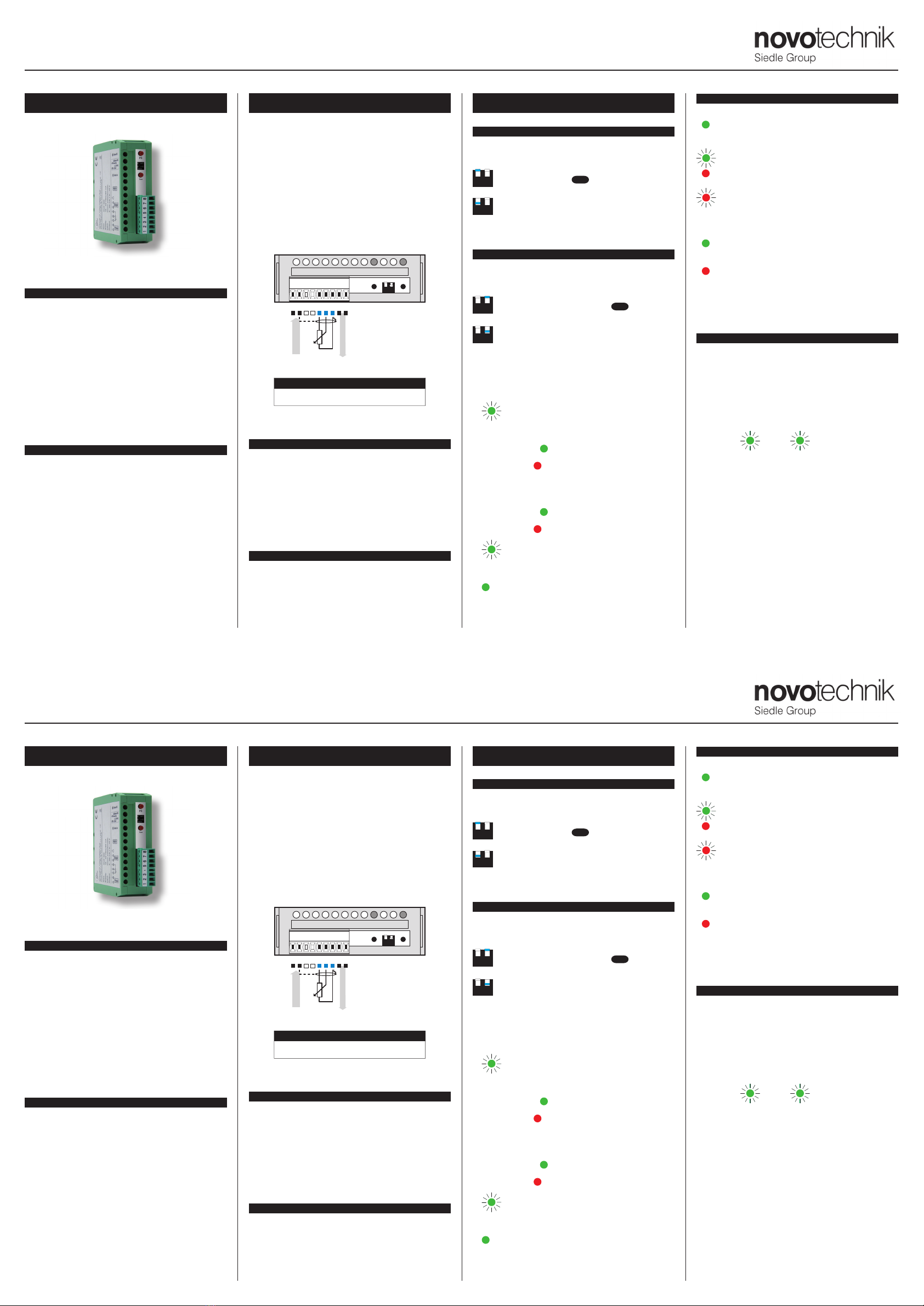
The type of analogue output can be selected by the first switch on
the front panel.
12
Output 4…20 mA DEF
12
Output 0…10 V
TEACH - IN
The Teach-in function is used to set the output range. To acti-
vate it, the second switch needs to be in a specified position.
12
Teach-in function is blocked DEF
12
Teach-in function activated
Teach-in
• flip the second switch into the „ON“ position
•LED „Lo“ starts flashing
• move the lin. pot slider into its minimum working range
(electrical signal is at its minimum)
• press button „Lo“ > LED „Lo“ is illuminated in green
if during the calibration process the electrical working range is reduced
by > 80 % , the red LED „Hi“ starts flashing
• LED „Lo“ is flashing
• move the linpot slider into its maximum working range
(electrical signal is at its maximum)
• press button „Hi“ > LED „Hi“ is illuminated in green
if during the calibration process the electrical working range is reduced
by > 80 % , the red LED „Hi“ starts flashing
•LED „Lo“ is flashing
• by flipping the second switch into the „OFF“ position you end the
calibration mode and enter the measuring mode
• LED „Lo“ is illuminated in green
LED SIGNALLING
LED „Lo“
transmitter is on
when button „Lo“ is pressed > calibration is „OK“
(in teach-in mode)
transmitter is in the calibration mode
measured value/input signal is out of the calibration
range
transmitter is in the calibration mode, but out of
range
LED „Hi“
when button „Hi“ is pressed > calibration is „OK“
(in teach-in mode)
range of calibration values is <= 19% of the range
(Accuracy and stability of the transmitted signal cannot be
guaranteed)
when button „Lo“ is pressed > calib. out of range
when button „Hi“ is pressed > calib. out of range
RESTORE FACTORY SETTINGS
This is how to return to the original manufacturer’s settings especially
when making a mistake during
the set up process.
• The device must be in powered off state
(No supply voltage attached).
• Switch dipswitch no. 2 to „ON and connect power supply while
pressing both push buttons simultaneously
•LEDs „Lo“ and „Hi“ are flashing alternatively
for approx. 3 seconds to indicate the process of restoration of
manufacturer’s settings
• To complete the restoration process, turn dipswitch no. 2
back to „OFF“
MUP 400
FAST DIGITAL TRANSMITTERS TO DIN RAIL
Power supply
Analog output
12 45678Lo Hi
12
+
---
+
+
Compensation of conduct up to 500 Ohm
! Analog output (4…20 mA)
2. CONNECTION
The power input leads should not be in the proximity of the incoming
low-potential signals.
Contactors, motors with larger input power and other efficient elements
should not be in the proximity of the instrument.
The lead into the input of the instrument (the measured quantity)
should be in sufficient distance from all power leads and appliances.
Provided this cannot be secured, it is necessary to use shielded leads
with connection to ground.
The instruments are tested in compliance with standards for use in
industrial areas, yet we recommend to abide by the above mentioned
principles.
SAFETY INSTRUCTIONS
Please,readthe enclosed safety instructions carefully and observethem!
These instruments should be safeguarded by either individual or shared
fuses (circuit breakers) with respect to their actual power consumption!
For safety information the EN 61 010-1 +A2 standard must be observed.
This instrument is not explosion-safe!
Our products are regularly not approved for aeronautic or aerospace
applications and are not allowed to be used in nuclear or military, in
particular ABC-relevant applications.
For more information see our Terms and Conditions.
TECHNICAL DATA
Transmitters of the MUP 400 series conform to the European regulation
89/336/EWG and the Ordinance168/1997 Sb.
They are up to the following European standards:
EN 61326-1
The instrument is suitable for non-restricted use in agricultural and
industrial areas.
1. DESCRIPTION
DESCRIPTION
The MUP 400 model range are very fast digital transmitters to DIN
rail with a Teach-in function.
MUP 400 Linear poten. analog output
(4…20mA or 0…10V )
The instrument is based on a single chip microcontroller, 24-bit A/D
and16-bit D/A converter, which ensures excellent accuracy, stability
and easy operation of the instrument.
The transmitter is in a plastic DIN box with a terminal board to rail
of 35 mm in width.
OPERATION
The instrument is controlled by two push buttons on the front panel.
The mode of the output signal and the access to the teach-in mode is
realised by a switch at the rear.
All settings are stored in the EEPROM memory (they are retained
even after the instrument is switched off).
3. SETTING
TYPES OF ANALOGUE OUTPUT
The type of analogue output can be selected by the first switch on
the front panel.
12
Output 4…20 mA DEF
12
Output 0…10 V
TEACH - IN
The Teach-in function is used to set the output range. To acti-
vate it, the second switch needs to be in a specified position.
12
Teach-in function is blocked DEF
12
Teach-in function activated
Teach-in
• flip the second switch into the „ON“ position
•LED „Lo“ starts flashing
• move the lin. pot slider into its minimum working range
(electrical signal is at its minimum)
• press button „Lo“ > LED „Lo“ is illuminated in green
if during the calibration process the electrical working range is reduced
by > 80 % , the red LED „Hi“ starts flashing
• LED „Lo“ is flashing
• move the linpot slider into its maximum working range
(electrical signal is at its maximum)
• press button „Hi“ > LED „Hi“ is illuminated in green
if during the calibration process the electrical working range is reduced
by > 80 % , the red LED „Hi“ starts flashing
•LED „Lo“ is flashing
• by flipping the second switch into the „OFF“ position you end the
calibration mode and enter the measuring mode
• LED „Lo“ is illuminated in green
LED SIGNALLING
LED „Lo“
transmitter is on
when button „Lo“ is pressed > calibration is „OK“
(in teach-in mode)
transmitter is in the calibration mode
measured value/input signal is out of the calibration
range
transmitter is in the calibration mode, but out of
range
LED „Hi“
when button „Hi“ is pressed > calibration is „OK“
(in teach-in mode)
range of calibration values is <= 19% of the range
(Accuracy and stability of the transmitted signal cannot be
guaranteed)
when button „Lo“ is pressed > calib. out of range
when button „Hi“ is pressed > calib. out of range
RESTORE FACTORY SETTINGS
This is how to return to the original manufacturer’s settings especially
when making a mistake during
the set up process.
• The device must be in powered off state
(No supply voltage attached).
• Switch dipswitch no. 2 to „ON and connect power supply while
pressing both push buttons simultaneously
•LEDs „Lo“ and „Hi“ are flashing alternatively
for approx. 3 seconds to indicate the process of restoration of
manufacturer’s settings
• To complete the restoration process, turn dipswitch no. 2
back to „OFF“
MUP 400
FAST DIGITAL TRANSMITTERS TO DIN RAIL
Power supply
Analog output
12 45678Lo Hi
12
+
---
+
+
Compensation of conduct up to 500 Ohm
! Analog output (4…20 mA)
5. INSTRUMENT DIMENSIONS4. TECHNICAL DATA
Input
Lin. potentiometer: 0,5…100 kOhm
Pot. power supply: 2,5 V,±0,2 %
Unlock:5…24 VDC
Instrument accuracy
TC: 10 ppm/°C
Accuracy: ±0,01 % of range
Rate: 7 500 meas./s
Overload capacity: 10x (t < 30 ms); 2x
Watch-dog: reset after 400 ms
Functions: Teach-in
Calibration: at 23°C and 40 % r.h.
Analog output
Type: programmable with resolution of 16 bit, type and range are
selectable
Non-linearity: 0,01 % of the range
TC: 10 ppm/°C
Rate: response to change of value < 0,2 ms
Voltage: 0…10 V, max. load 1 kOhm
Current: 4…20 mA, compensation of conduct up to 500 Ohm
Ripple: 5 mV of residual corrugation upon input signal 10 V
Power supply
18…30 VDC, ±10%, max. 2,5 W
10…30 VDC, ±10%, max. 2,5 W, isolated*
Mechanic properties
Material: PA 66S, incombustible UL 94 V0, green
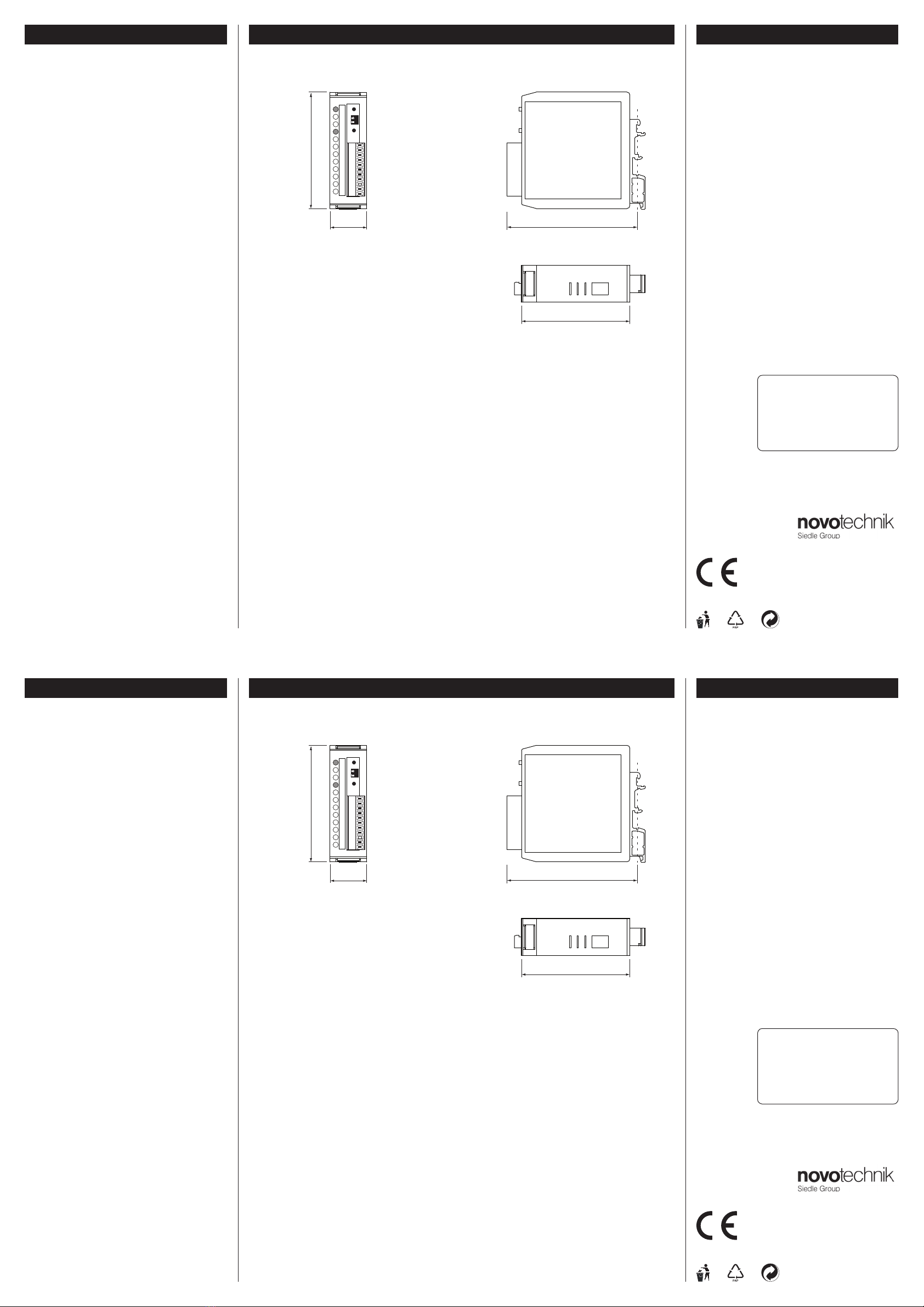
Dimensions: 90,5 x 79 x 25 mm
Installation: to DIN rail, width 35 mm
Operating conditions
Connection: connector terminal board - conductor section up to 1,5 mm2
Stabilizat. period: within 15 minutes after switch-on
Working temp.: -20°…60°C
Storage temp.: -20°…85°C
Cover: IP 20 (NEMA 1)
El. safety: EN 61010-1, A2
Dielectric strength: 1,5 kV after 1 min between supply and input/ouput
Insulation resist.: for pollution degree II, measuring cat. III.
power supply > 550 V (ZI), 255 V (DI)
EMC: EN 61326-1
6. CERTIFICATE OF GUARANTEE
Product: MUP 400
Manufact.No.: . . . . . . . . . . . . . . . . . . . .
Date of sale: . . . . . . . . . . . . . . . . . . . .
For this instrument applies a guarantee period of 24 months of the
date of sale to the user.
Defects occuring during this period due to manufacturing error or due
to material faults shall be eliminated free of charge.
For instrument quality, function and construction the guarantee shall
apply provided the instrument was connected and used accurately in
compliance with the instructions for use.
The guarantee does not apply to defects caused by:
- mechanical damage
- transportation
- intervention of unqualified person including the user
- irreversible event
- other unprofessional interference
The manufacturer performs guarantee and post-guarantee repairs
unless provided for othervise.
Installation to DIN rail of 35 mm width
79 mm
25 mm
74 mm
Lo Hi
12
90,5 mm
Side viewFront view
Stamp, signature
Novotechnik Messwertaufnehmer OHG
Postfach 4220, 73745 Ostfildern (Ruit)
Horbstraße 12, 73760 Ostfildern (Ruit)
Telefon +49 711 4489-0
Telefax +49 711 4489-118
www.novotechnik.de
TECHDOK - MUP 400 - 2016 - 1v4 - en
*see the order code
5. INSTRUMENT DIMENSIONS4. TECHNICAL DATA
Input
Lin. potentiometer: 0,5…100 kOhm
Pot. power supply: 2,5 V,±0,2 %
Unlock:5…24 VDC
Instrument accuracy
TC: 10 ppm/°C
Accuracy: ±0,01 % of range
Rate: 7 500 meas./s
Overload capacity: 10x (t < 30 ms); 2x
Watch-dog: reset after 400 ms
Functions: Teach-in
Calibration: at 23°C and 40 % r.h.
Analog output
Type: programmable with resolution of 16 bit, type and range are
selectable
Non-linearity: 0,01 % of the range
TC: 10 ppm/°C
Rate: response to change of value < 0,2 ms
Voltage: 0…10 V, max. load 1 kOhm
Current: 4…20 mA, compensation of conduct up to 500 Ohm
Ripple: 5 mV of residual corrugation upon input signal 10 V
Power supply
18…30 VDC, ±10%, max. 2,5 W
10…30 VDC, ±10%, max. 2,5 W, isolated*
Mechanic properties
Material: PA 66S, incombustible UL 94 V0, green
Dimensions: 90,5 x 79 x 25 mm
Installation: to DIN rail, width 35 mm
Operating conditions
Connection: connector terminal board - conductor section up to 1,5 mm2
Stabilizat. period: within 15 minutes after switch-on
Working temp.: -20°…60°C
Storage temp.: -20°…85°C
Cover: IP 20 (NEMA 1)
El. safety: EN 61010-1, A2
Dielectric strength: 1,5 kV after 1 min between supply and input/ouput
Insulation resist.: for pollution degree II, measuring cat. III.
power supply > 550 V (ZI), 255 V (DI)
EMC: EN 61326-1
6. CERTIFICATE OF GUARANTEE
Product: MUP 400
Manufact.No.: . . . . . . . . . . . . . . . . . . . .
Date of sale: . . . . . . . . . . . . . . . . . . . .
For this instrument applies a guarantee period of 24 months of the
date of sale to the user.
Defects occuring during this period due to manufacturing error or due
to material faults shall be eliminated free of charge.
For instrument quality, function and construction the guarantee shall
apply provided the instrument was connected and used accurately in
compliance with the instructions for use.
The guarantee does not apply to defects caused by:
- mechanical damage
- transportation
- intervention of unqualified person including the user
- irreversible event
- other unprofessional interference
The manufacturer performs guarantee and post-guarantee repairs
unless provided for othervise.
Installation to DIN rail of 35 mm width
79 mm
25 mm
74 mm
Lo Hi
12
90,5 mm
Side viewFront view
Stamp, signature
Novotechnik Messwertaufnehmer OHG
Postfach 4220, 73745 Ostfildern (Ruit)
Horbstraße 12, 73760 Ostfildern (Ruit)
Telefon +49 711 4489-0
Telefax +49 711 4489-118
www.novotechnik.de
TECHDOK - MUP 400 - 2016 - 1v4 - en
*see the order code


