Funktionseinstellung (IMS-Ai-Uni/24VDC)
Mit DIP-Schaltern (S1) lässt sich die Übertra-
gungscharakteristik einstellen (siehe auch dazu
Tab. 1 und Fig. 3). Bei jedem Ausgang kann ein
Dead-zero-Signal (DZ) in ein Live-zero-Signal
(LZ) gewandelt werden und umgekehrt.
LZ Eingehende Signale mit
0...20 mA bzw. 0...10 V werden
in 4...20 mA gewandelt
DZ Eingehende Signale mit
4...20 mA werden in 0...20 mA
bzw. 0...10 V gewandelt
1 : 1 Die Signale werden ohne Beein-
flussung übertragen
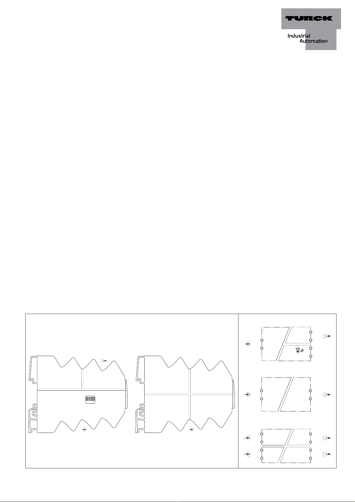
Installation und Montage (Fig. 4)
Das Gerät ist aufschnappbar auf Hutschiene
(EN 50022).
Sorgen Sie für eine ausreichende Wärmeabfuhr.
Führen Sie die Montage und Installation den
gültigen Vorschriften entsprechend durch.
Dafür sind Sie als Betreiber verantwortlich.
Schützen Sie das Gerät ausreichend gegen
Staub, Schmutz, Feuchtigkeit und andere
Umwelteinflüsse.
Auch gegen energiereiche Strahlung, Risiken
mechanischer Beschädigung, unbefugter
Veränderung und zufälliger Berührung müssen
Vorkehrungen getroffen werden.
Führen Sie sämtliche Installationen EMV-ge-
recht durch.
IMS-Ai-Uni/24VDC / IMS-Ai-DLi-DLi/L / IMS-Ai-DLi-22-DLi/L
Function adjustment (IMS-Ai-Uni/24VDC)
The transfer characteristics can be adjusted
(see also table 1 and Fig. 3) with DIP switches
(S1). At each output a dead-zero signal (DZ)
can be converted into a live-zero signal (LZ) and
vice versa.
LZ Incoming signals with
0...20 mA or 0...10 V are
converted into 4...20 mA
DZ Incoming signals with
4...20 mA are converted into
0...20 mA or 0...10 V
1 : 1 The signals are transferred without
any modification
Mounting and installation (Fig. 4)
The device can be snaped on DIN rails
EN 50022).
It must be ensured that heat is conducted away
from the device. Mounting and installation must
be carried out in accordance with the applica-
ble regulations. The operator is responsible for
compliance with the regulations.
The device must be protected against dust,
dirt, moisture and other environmental influ-
ences as well as against strong electromagnetic
emissions. It should also be protected against
the risks of mechanical damaging, unauthorised
access and incidental contact.
All installations must be carried out observing
the regulations of EMC protection.
Réglage des fonctions (IMS-Ai-Uni/24VDC)
Les commutateurs DIP (S1) en face frontale per-
mettent de régler la caractéristique de transmis-
sion. (voir aussi tableau 1 et Fig. 3). Un signal
dead-zéro (DZ) peut être converti en un signal
live-zéro (LZ) à chaque sortie et inversement.
LZ Les signaux intenses de
0...20 mA ou 0...10 V sont
convertis en 4...20 mA
DZ Les signaux intenses de
4...20 mA sont convertis en
0...20 mA ou 0...10 V
1 : 1 Les signaux sont transmis sans
influence
Montage et installation (Fig. 4)
L‘appareil est encliquetable sur rail symétrique
(EN 50022).
Une évacuation suffisante de la chaleur est
nécessaire. Le montage et l’installation doivent
être effectués conformément aux prescriptions
locales valables, dont le respect est la respon-
sabilité de l’exploitant.
L‘appareil doit être suffisamment protégé
contre les poussières, la pollution, l‘humidité
et les autres influences d‘environnement, ainsi
que contre le rayonnement fort, les risques de
dommages mécaniques, la modification non-
autorisée et les contacts accidentels.
Toutes les installations doivent être effectuées
conformément à la CEM.
D201341 0508 *D201341ßß0508*
Tab. 1 Übertragungscharakteristik (IMS-Ai-Uni/24VDC)/transfer characteristics (IMS-Ai-Uni/24VDC)/caractéristique de transmission (IMS-Ai-Uni/24VDC)
è0...20 mA 4...20 mA 0...10 V
ç
0...20 mA/0...10 V 1 : 1 DZ ➞LZ 1 : 1
4...20 mA LZ ➞DZ 1 : 1 LZ ➞DZ
0...20 mA
0...20 mA
0...20 mA
4...20 mA
4...20 mA
4...20 mA
0...10 V
0...10 V
0...10 V
0...10 V
0...20 mA
4...20 mA
0...10 V
0...20 mA
4...20 mA
0...10 V
0...20 mA
4...20 mA
In ut Out ut
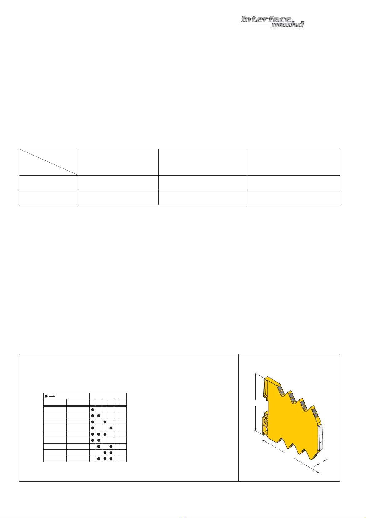
Switch ON S1
123456
Fig. 3 Einstellung der DIP-Schalter (IMS-Ai-Uni/24VDC)
Adjustment of the DIP-Switches (IMS-Ai-Uni/24VDC)
Réglage des commutateurs DIP (IMS-Ai-Uni/24VDC)
Fig. 4
90
92,5
6,2
Irrtümer und Änderungen vorbehalten / Subject to change without notice / Sous réserve de modifications •© Hans Turck GmbH & Co. KG 2008
Hans
T
urck
GmbH
&
Co.
KG
•Witzlebenstraße 7 •45472 Mülheim/Ruhr •Germany •Tel. +49 (0) 208/4952-0 •Fax +49 (0) 208/4952-264 •[email protected] •www.turck.com