3 TY-KJ16-001A Rev.2
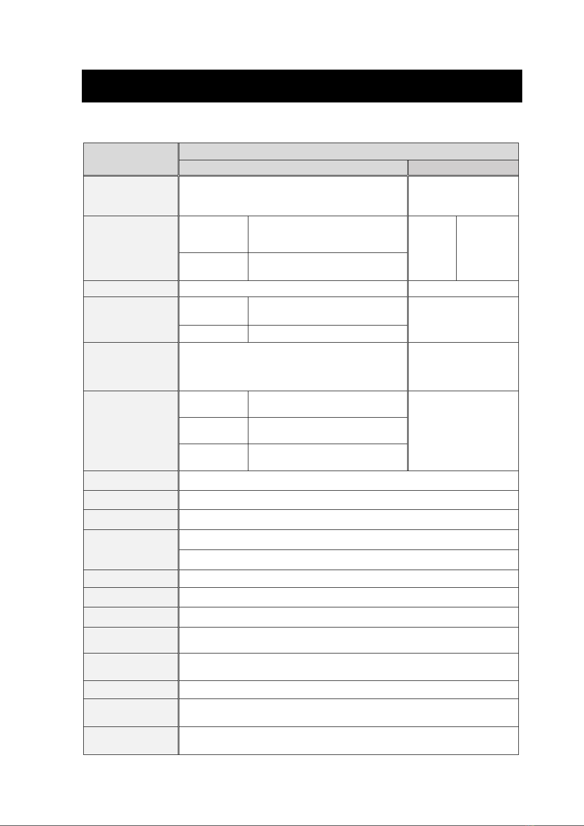
■Precautions for Handling Product
●Do not give excessive load, vibration, and shock. Damage to the
product and release of a measured object may be caused, which
results in injury or damage to the surrounding environment.
●Repeated applied pressure should be within the rated pressure
range. Do not apply pressure over the maximum allowable
pressure. Damage to pressure elements may be caused, which
results in injury or damage to the surrounding environment.
●Do not use this product for measured objects corrosive to
materials of wetted parts and gas contact parts.
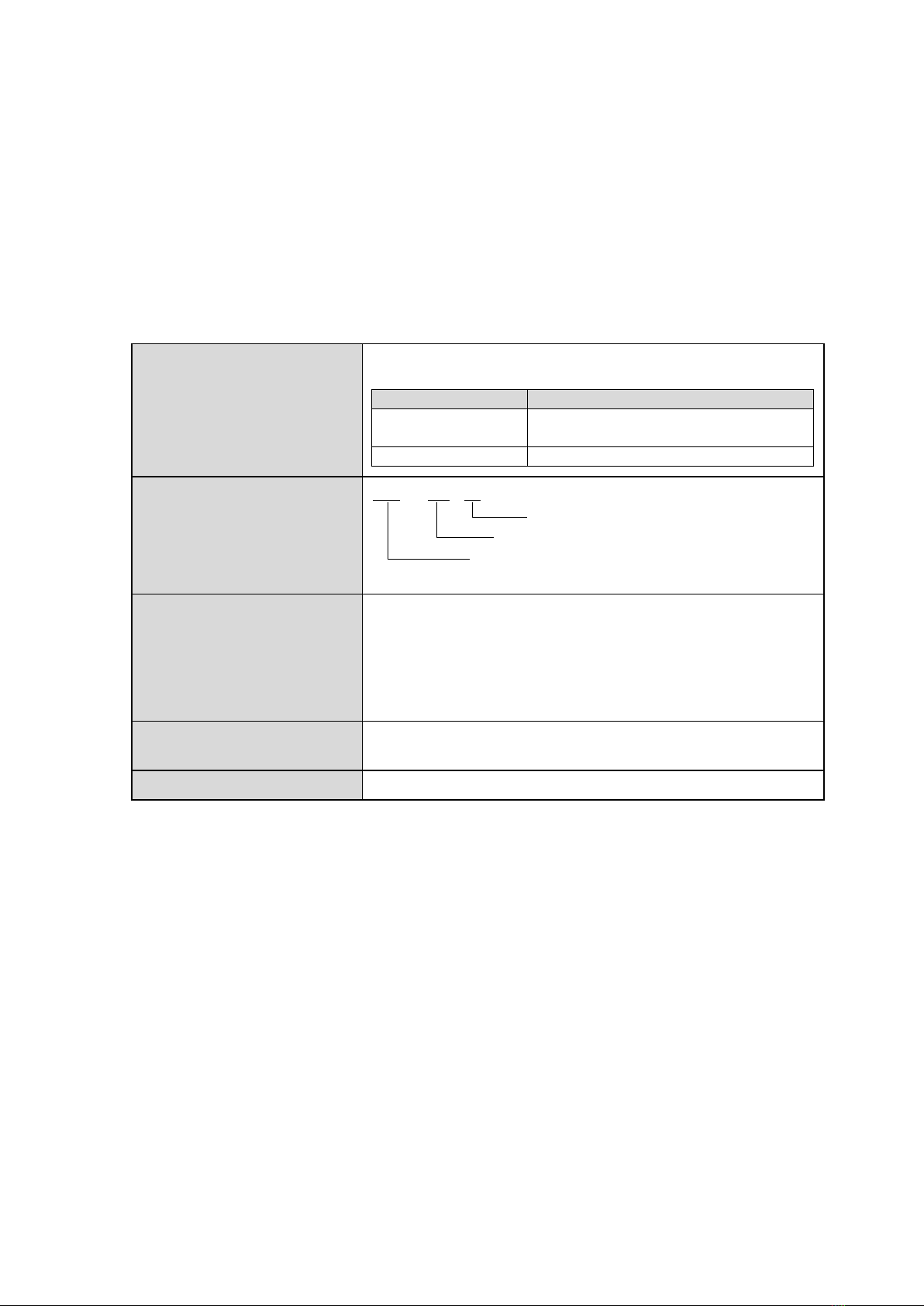
●This product is explosion-proof.
Do not use, install, store, or perform work that degrades the
explosive-proof performance in the environments listed below.
1) Installation that degrades the explosive-proof performance of
the intrinsically safe circuit
• A place with an ambient temperature of above 60 °C*1
• A place exposed to direct sunlight*1
• A place exposed to water such as rain*2
• A place where atmosphere contains moisture, salt, or
sulfur content*2
2) Wiring that degrades the explosive-proof performance of the
intrinsically safe circuit*3
3) Product inspection in a hazardous area*4
●Do not use non-designated batteries and power supply.
Use of them causes failures, fires, or electric shocks.
●If failures or malfunctions of this product may threaten human
life directly or cause harm to human bodies, do not use the
product.
●Do not modify this product. Disassembly or modification of the
product, or modification to add new functions may cause harm
to human bodies.
●When a measuring object is oxygen, use a degreased product.
General products may have oil remaining inside, which may cause
the risk of ignition or explosion when oil reacts to oxygen.
●Conduct wiring correctly according to the wiring nameplate or
the wiring procedure described in the user's manual. Incorrect
wiring may cause failures or fires.
●Use the product within the operating temperature range.
Otherwise, the product fails or is damaged, which causes injury
or damage to the surrounding environment.
* These precautions are selected from our common safety precautions for all products that correspond to
this product. KJ16-specific precautions are further described in detail in the following sections.
WARNING