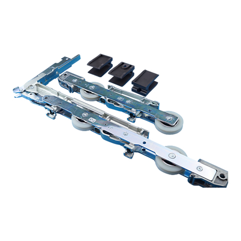
Siegenia PSK PORTAL 160 PLUS LM User manual

22.11.2013 Page 1
PSK PORTAL 160 PLUS LM
Parallel tilt & slide (PSK) hardware
For light metal profiles a cavity of 21 mm
Assembly instructions
H48.PSKLMS001EN
Technical specifications and colours are subject to change
Table of contents
Size range............................................................. Page 1 Vertical section, top....................................................................Page 11
Layout of fittings.................................................... Page 2 Horizontal section (l)..................................................................Page 12
List of fittings part1 ............................................... Page 3 Horizontal section (II) ................................................................Page 13
List of fittings part2 ............................................... Page 4 Frame: frame part dimensions ...................................................Page 14
Important instructions, abbreviations................... Page 5 Window frame: mounting the running and guiding rail ..........Page 15
Design variations.................................................. Page 6 Vertical section, bottom..............................................................Page 16
Fitting diagram scheme C (I) ............................... Page 7 Preparing the sash frame...........................................................Page 17
Fitting diagram scheme C (II) .............................. Page 8 Sash: ZV assembly .....................................................................Page 18
Scheme C.............................................................. Page 9 Sash frame: mounting the PSK components .............................Page 19
Hinging and unhinging the stay arms ................. Page 10 Inserting the sliding sashes and adjustment possibilities..........Page 20
The size ranges mentioned above apply for the PSK-PORTAL 160 PLUS LM fitting from SIEGENIA.
Also effective are the specifications of the profile manufacturers or system owners, especially with regard to
possible restrictions on sash dimensions, sash weight and lock spacing.
Observe any special manufacturing specifications or processing guidelines explicitly.
Size range
Sash width (mm) 700 to 1,6501)
Sash height (mm) 850 to 2,400
Exterior width of frame (mm) Depends on the profile system,
determined by the sash width,
for scheme A: max. 3,460
Rebate thickness (mm) 7 to 12
Sash weight (kg) Max. 160
Total frame to sash clearance (mm) 118
1) For sash widths < 960 mm, the sash height must not be greater than 2.5x the sash width.

H48.PSKLMS001EN/22.11.2013 Page 2
Layout of fittings
1a
2
5
27
12
11
15
33 22
34
12 15
13
4
3
26
12
11
18
17
16
12
12
11
38
88
9
39
23
24
29
36 12
13
77
14
14
32 31 30
12
13
12
13
39
28
37
35
6
25
21
10
7
1010
1b
1a Handle Si-line PSK
1b Handle LM Globe PSK
2Bogie wheels V
3Bogie wheels H
4Supporting part S LM right
5Supporting part S LM left
6Cheese head screw M5 x 18
7Flowdrill screw M5 x 20
8Slider
9Key
10 Clamping piece EUL
11 Corner drive VSU
12 Striker
13 Slider MV
14 Tilt lock
15 Tilt locking part
16 Cheese head screw M5 x 12
17 Mishandling device LM
18 Coupling bracket LM
21 Cover rail L
22 Connecting rod
23 Guiding rail
24 Cover rail F
25 Running rail
26 Cover cap L right
27 Cover cap L left
28 Cover cap F right
29 Cover cap F left
30 Stop
31 Stop body
32 Stop sleeve
33 Locking part
34 Supporting piece L
35 Tilt stay
36 Cover rail K LM
37 Cover cap K LM right
38 Cover cap K LM left
39 Distance piece
For list of fittings, see pages 3 and 4.
PSK PORTAL 160 PLUS LM

H48.PSKLMS001EN/22.11.2013 Page 3
Quantity/Scheme Material no.
Item A G C K Description silver white brown
generally required
10...1 0...1 0...2 0...2 Handle Si-line PSK LM MHSS2000-52501_ 875445 875476
0...1 0...1 0...2 0...2 Handle LM Globe PSK MHGS2000-52501_ MHGS2000-50401_ MHGS2000-53301_
no illus.
0...1 0...1 0...2 0...2 Handle PSK lockable See LMde1337 in the Aluminium planning manual
1112
Crt. bg. wh. PSK 160 LM
PLUS
right
lef t
PMKF7031-10001_
PMKF7032-10001_
21122
Bogie wheels V right front PLWJ0011-10001_
(PSK 160 Plus) left front PLWJ0012-10001_
31111
Bogie wheels H right rear PLWJ0021-10001_
(PSK 160 Plus) left rear PLWJ0022-10001_
41111Supporting part S LM right 316212-100
51111Supporting part S LM left 316211-100
6551010Cheese head screw M5 x 18 824337
712 12 24 24 Flowdrill screw M5 x 20 317276-001
no illus.
30 30 60 60 Flowdrill screw M4 x 20 317277-001
1122Bag accessories PSK PORTAL PMZJ0030-00001_
82244Slider PFZJ0020-09901_
91122Key PORTAL 719381
1122ZV LM PSK VAR. SET MMZV0040-10001_
10 3366Clamping piece EUL 859322
11 3366Corner drive VSU 819272
12 881616Striker 859322
13 4488Slider MV 849149
14 2244Tilt lock 819173
15 2244Tilt locking part 819197
0...1 0...1 0...1 0...2 Coupling set FBS-G 9 mm MMKL0030-10001_
0...1 0...1 0...1 0...2 Coupling set FBS-G 10 mm MMKL0010-10001_
0...1 0...1 0...1 0...2 Coupling set FBS-G ORH 12 mm MMKL0040-10001_
16 2222Cheese head screw M5 x 12 859322
17 1111Mishandling device LM 819272
18 1111Coupling bracket 849149
--1-
Coupling set LM-D MMKL0020-10001_
19 --2-Cheese head screw M5 x 12 859322
20 --1-Coupling bracket 849149
7 - 10
X
12
Design variations for coupling set
FBS-G (16 - 18)
ORH XMaterial no.
7 - 10 mm ≤8.5 mm MMKL0030-10001_
7 - 10 mm ≤7.5 mm MMKL0010-10001_
12 mm ≤7 mm MMKL0040-10001_
For layout of fittings, see pages 2, 7 and 8.
List of fittings part1PSK PORTAL 160 PLUS LM

H48.PSKLMS001EN/22.11.13 Page 4
Item
Quantity/Scheme
Description
Material no.
AG1)
1) For scheme G, design profile set only for 2/3 of total frame width
C2)
2) For scheme C, symmetrical design; point of separation must be between the sliding sashes
K3)
3) For scheme K, symmetrical design
Basic Material no. silver RAL 9003
white
RAL 8022
brown
dependent on sash width (FB) and frame width (RAB)
1122
Profile set PSK LM PLUS
Size Length FB RAB
(in mm) (in mm) (in mm)
Sz. 87/200 700 to 900 to 2,000
Sz. 107/240 901 to 1,100 2,001 to 2,400
Sz. 130/286 1,101 to 1,300 2,401 to 2,860
Sz. 160/346 1,301 to 1,650 2,861 to 3,460
PMPF7050
PMPF7060
PMPF7070
PMPF7080
...-52501_
...-52501_
...-52501_
...-52501_
...-50201_
...-50201_
...-50201_
...-50201_
...-51201_
...-51201_
...-51201_
...-51201_
21 1122
Cover rail L
Sz. 87 865
Sz. 107 1,065
Sz. 130 1,295
Sz. 160 1,550
PPAJ0130
PPAJ0140
PPAJ0150
PPAJ0160
-52501_
-52501_
-52501_
-52501_
50201_
50201_
50201_
50201_
51201_
51201_
51201_
51201_
22 1122
Connecting rod
Sz. 87 585
Sz. 107 785
Sz. 130 1,015
Sz. 160 1,270
714782
714751
714768
714775
23 1122
Guiding rail
Sz. 200 2,000
Sz. 240 2,400
Sz. 286 2,860
Sz. 346 3,460
890165
890196
890226
890257
24 1122
Cover rail F
Sz. 200 2,000
Sz. 240 2,400
Sz. 286 2,860
Sz. 346 3,460
889862
889916
889961
890011
25 1122
Running rail
Sz. 200 2,000
Sz. 240 2,400
Sz. 286 2,860
Sz. 346 3,460
PPLJ0130-52401_
PPLJ0140-52401_
PPLJ0150-52401_
PPLJ0160-52401_
1122
Bag Cover cap set PSK LM PLUS PMZF0010 -02501_ ...-00201_ ...-01201_
26 1122
Cover cap L right PKAF7011 -02501_ 00201_ 01201_
27 1122
Cover cap L left PKAF7012 -02501_ 00201_ 01201_
28 1122
Cover cap F right PKAJ0041 -02501_ 889770 889800
29 1122
Cover cap F left PKAJ0042- -02501_ 889824 889855
1122
Bag accessories
Running rail PSK PLUS PMZJ0050 -100011 ...-100011 ...-01201_
30 1122
Stop 358850-001 358850-001 358850-004
31 1122
Stop body 381290-001 381290-001 381290-002
32 1122
Stop sleeve 381290-001 381290-001 381290-002
33 1122
Locking part 358850-001 358850-001 358850-004
34 1122
Supporting piece L 381290-001 381290-001 381290-002
dependent on sash width (FB) and frame width (RAB)
35 1122
Tilt stay PSK 160
Size Length FB
(in mm) (in mm)
87 620 700 to 900
107 820 901 to 1,100
130 1,020 1,101 to 1,300
160 1,220 1,301 to 1,650
716526
716533
716540
716557
1122
Bag cover rail K LM
PSK 160
Size FB
(in mm)
87 700 to 900
107 901 to 1,100
130 1,101 to 1,300
160 1,301 to 1,650
PMPF7090
PMPF7100
PMPF7110
PMPF7120
...-52501_
...-52501_
...-52501_
...-52501_
...-50201_
...-50201_
...-50201_
...-50201_
...-51201_
...-51201_
...-51201_
...-51201_
36 1122
Cover rail K LM
Sz. 87 940
Sz. 107 1,140
Sz. 130 1,370
Sz. 160 1,670
PPAJ0130-
PPAJ0140-
PPAJ0150-
PPAJ0160-
52501_
52501_
52501_
52501_
50201_
50201_
50201_
50201_
51201_
-51201_
-51201_
-51201_
37 1122
Cover cap K LM
right
714782
714751
714768
714775
38 1122
Cover cap K LM
left
890165
890196
890226
890257
39 1122
Distance piece K PSK LM
889862
889916
889961
890011
For layout of fittings, see pages 2, 7 and 8.
List of fittings part2PSK PORTAL 160 PLUS LM

H48.PSKLMS001EN/22.11.2013 Page 5
Important Instructions
– Please pay attention to our “Hardware for Sliding Doors and Windows” product information.
– For the PSK PORTAL 160 Plus LM fitting from SIEGENIA the size ranges detailed on page 1 apply.
Furthermore, the specifications provided by the profile manufacturers or system owners also apply, especially any information regarding
possible restrictions on sash dimensions, sash weight and lock spacing.
Observe any special manufacturing specifications or processing guidelines explicitly. The specifications given for screw-in speeds and torques
must be adhered to.
– If the parallel tilt & slide element is subjected to excessive strain, the sash can, in the worst case, jump and fall out of its guide and, in doing so,
cause serious injuries.
If it is expected that the parallel tilt & slide element will be subject to excessive strain from being closed with force (use in schools,
nursery schools, etc.), appropriate measures must be taken to prevent this from happening.
For example:
– move the stop to reduce the opening width or
– install a lockable handle to prevent unauthorised use.
In case of doubt, be sure to contact your SIEGENIA sales consultant.
– The fittings specified in these assembly instructions are electro-galvanised and finished using a special technique; they
comply with DIN EN 1670. They must not be used in environments where the air contains aggressive or corrosive components, or salt.
– Select your complete set of fittings only from the SIEGENIA range of fittings. Damage could otherwise occur, for which we accept no liability.
– All fittings must be properly mounted as per the description on pages 10 to 20. Do not overtighten the screws.
– The parallel tilt & slide elements may be surface treated only before the fittings are assembled. Treating these surfaces at a later stage can
reduce the functional capacity of the fittings. In such cases we are not obliged to provide a guarantee.
– When inserting blocks, be sure to observe technical guideline no. 3 published by the German Glazing Trade
[Glaserhandwerk], “Blocking glazing units” [Klotzung von Verglasungseinheiten].
– Never use acid cure sealants as they may cause the fittings to corrode.
– Keep the sliding bump (on the running rail) and all rebates free from deposits and dirt, especially from remnants of cement and plaster. Avoid
exposing the fittings directly to water and do not let cleaning agents come into contact with the fittings.
– Attach the instruction label (sliding direction DIN left
or DIN right) to the integrated parallel tilt & slide sash in a clearly
visible location.
The instruction label is located in “Carton PSK 160 LM.”
Remove the applicable segment from the respective label and
stick it to the window sash.
Disclaimer of liability
We assume no liability for loss of function of or damage to the fittings (or to the fitted parallel tilt & slide
elements) resulting from insufficient tendering, failure to follow these assembly instructions or force being applied to the fittings
(e.g. through improper use).
Hebelstellung PZ mit Hebel innen und außen
Handle position PZ with handle inside and outside
Position de avec poignée
intérieure et extérieure
poignée à cylindre
PSK PORTAL
DIN rechts
DIN right
DIN droit
04 87
Bitte den passenden Aufkleber ablösen und gut sichtbar am Parallel-Schiebe-Kippflügel anbringen.
Please remove suitable sticker and affix it in a clearly visible way to the sash of the installed parallel-tilt-sliding unit.
Retirer l´auto-collant pertinent et le placer bien visiblement sur le vanail coulissant.
Hebelstellung Standard
Handle position basic
Position standard del poignée
Hebelstellung wie Dreh-Kippbes hlag
Handle position as turn and tilt
Position de la poignée selon OB
Schiebestellung
Sliding position
Position coulissante
Verschlußstellung
Locked position
Position fermée
Kippstellung
Tilt position
Position pivotante
Schiebestellung
Sliding position
Position coulissante
Verschlußstellung
Locked position
Position fermée
Kippstellung
Tilt position
Position pivotante
Schiebestellung
Sliding position
Position coulissante
Verschlußstellung
Locked position
Position fermée
Kippstellung
Tilt position
Position pivotante
Hebelstellung PZ mit Hebel innen und außen
Handle position PZ with handle inside and outside
Position de avec poignée
intérieure et extérieure
poignée à cylindre
PSK PORTAL
DIN links
DIN left
DIN gauche
Material-Nr. 7004 88
Bitte den passenden Aufkleber ablösen und gut sichtbar am Parallel-Schiebe-Kippflügel anbringen.
Please remove suitable sticker and affix it in a clearly visible way to the sash of the installed parallel-tilt-sliding unit.
Retirer l´auto-collant pertinent et le placer bien visiblement sur le vanail coulissant.
Hebelstellung Standard
Handle position basic
Position standard del poignée
Hebelstellung wie Dreh-Kippbes hlag
Handle position as turn and tilt
Position de la poignée selon OB
Schiebestellung
Sliding position
Position coulissante
Verschlußstellung
Locked position
Position fermée
Kippstellung
Tilt position
Position pivotante
Schiebestellung
Sliding position
Position coulissante
Verschlußstellung
Locked position
Position fermée
Kippstellung
Tilt position
Position pivotante
Schiebestellung
Sliding position
Position coulissante
Verschlußstellung
Locked position
Position fermée
Kippstellung
Tilt position
Position pivotante
FGuidingrail
FB Sash width
FFB Sash rebate width
FFH Sash rebate height
FH Sash height
G Handle height
HRear
LBogiewheels
MMiddle
MV Centre lock
OKFF Finished floor level
PZ Profile cylinder
RAB Exterior width of frame
RAH Exterior height of frame
RFB Frame rebate width
SHeavyversion
S-ES Steel-enhanced security
SW Key dimension
ORH Over rebate height
VFront
VS Locking side
VSU Locking side, bottom
ZV Central locking part
Abbreviations
The following abbreviations are used in these assembly instructions:
Important instructions, abbreviationsPSK PORTAL 160 PLUS LM

H48.PSKLMS001EN/22.11.13 Page 6
1) For max. sash profile - installation depth up to 100 mm , use rose Si-line FAVORIT (40b).
over 100 mm , use rose PSK EUROLINE (40a).
2) For installation dimensions and ordering information, see assembly instructions LMde1361/LMde1364 in the Aluminium planning manual.
Item Quan-
tity Description Material no.
40a 1 Rose PSK EUROLINE silver for profile installation depth over 73 mm PHZE0010-52401_
1
Rose PSK EUROLINE brown (RAL 8022) for profile installation depth over 73 mm PHZE0010-51201_
1
Rose PSK EUROLINE white (RAL 9003) for profile installation depth over 73 mm PHZE0010-50201_
40b 1 Rose Si-line FAVORIT silverfor profile installation depth up to 73 mm 869826
1
Rose Si-line FAVORIT dark bronze for profile installation depth up to 73 mm 869833
1
Rose Si-line FAVORIT white for profile installation depth up to 73 mm 862605
41 1 Removable handle Si-line white for profile installation depth up to 73 mm ZHAN0010-50201_
42 1 Gear set M6 MMGI0090-10003_
43 2 Oval head countersunk screw M5 x 40 shortened by customer 800829
44 2 Countersunk screw M5 x 35 included in pack unit gear M6 –
40a 41
40b
43
44
42 2)
Scheme A
DIN left or DIN right
Scheme G
1 sliding sash/2 stationary sashes*
1 sliding sash/1 stationary sash*
2 sliding sashes/2 stationary sashes*
2 sliding sashes/1 stationary sash
Scheme C
Scheme K
*) Instead of stationary sashes, turning sashes are also possible.
Turning sashes are available only with rose PSK PORTAL
EUROLINE (40a) or rose Si-line FAVORIT (40b) and
removable handle (41).
100 1)
23 2)
5
12
23
2)
422)
Design variationsPSK PORTAL 160 PLUS LM

H48.PSKLMS001EN/22.11.2013 Page 7 H48.PSKLMS001EN/22.11.2013 Page 8
1010
Ø 5,2
S6 = G2 - 125
10
Ø 5,2
10
FB/2 - 18
FB - 160
FB/2 - 18
FB - 193
S7 = FB/2 - 265
Frame parts and dri e rod lengths for two sash Schema C
for other dimensions please see pages 14 and 18
1a Handle Si-line PSK
1b Handle LM Globe PSK
2Bogie wheels V
3Bogie wheels H
4Supporting part S LM right
5Supporting part S LM left
6Cheese head screw M5 x 18
7Flow drill screw M5 x 20
8Slider
9Key
10 Clamping piece EUL
11 Corner drive VSU
12 Striker
13 Slider MV
14 Tilt lock
15 Tilt locking part
16 Cheese head screw M5 x 12
17 Mishandling device LM
18 Coupling bracket LM
19 Cheese head screw M5 x 12
20 Coupling bracket LM
21 Cover rail L
22 Connecting rod
23 Guiding rail
24 Cover rail F
25 Running rail
26 Cover cap L right
27 Cover cap L left
28 Cover cap F right
29 Cover cap F left
30 Stop
31 Stop body
32 Stop sleeve
33 Locking part
34 Supporting piece L
35 Tilt stay
36 Cover rail K LM
37 Cover cap K LM right
38 Cover cap K LM left
39 Distance piece
1a
2
5
27
15
33 22
34
12 15
13
4
3
26
12
11
18
17
16
12
11
37
8 8
9
39
23
36 12
13
7
14
14
32 31 30
7
12
13
12
13
39
28
37
35
6
25
21
38
36
1a
12
19
20
8
39
6
39
8
9
12
13
29
38
35
11
13
12
12
13
12
11
12
11
26
7
4
7
7
5
7
323130
34
3
22
15
15 12
13
27
11
14 14
10
10
10 10
10
10
21
7
24
7
1b 1b
For list of fittings, see pages 3 and 4.
Fitting diagram scheme C (I)PSK PORTAL 160 PLUS LM Fitting diagram scheme C (I)PSK PORTAL 160 PLUS LM Fitting diagram scheme C (II)PSK PORTAL 160 PLUS LM

H48.PSKLMS001EN/22.11.2013 Page 9
min. 4
2. 1.
2 sliding sashes/2 stationary sashes
Important: Main and secondary sashes must be labelled
accordingly to prevent faulty operation.
The sliding sashes may be operated only in the
order specified below.
To open: main sash first [1.],
then secondary sash [2.]
To close: secondary sash first [2.],
then main sash [1.]
For layout of fittings, see pages 7 and 8.
Scheme CPSK PORTAL 160 PLUS LM

H48.PSKLMS001EN/22.11.2013 Page 10
1. Insert stay arm (a) into slider (8) as shown in illustration opposite.
2. Make sure you hear the top hinge pin (b) click into place in slider (8).
3. Pull gently on stay arm (c) to make sure that the top hinge pin
is securely in place in slider.
Snap in stay arm of tilt stay (35) into slider (8).
1. Insert key (9) into designated opening on slider (8)
(d) and turn 90 degrees.
2. Pull stay arm down in direction of arrow (e).
Note: The stay arm safety device in the slider (8) may be
opened only by using the SIEGENIA key (9).
Unhinging the stay arms
Sequence for securing (hinging the stay arm)
Disassembling the stay arm
If top hinge bolt is not locked in
place,
there is a risk of injury from a
falling window sash.
▲Snap in top hinge pin on stay arm in slider (8).
(a)
Klick !
8
(b)
(c)
(Stay arm)
(Slider)
(Top hinge pin)
(d)
(e)
For inserting the sliding sashes, see page 20.
9
8
23
Hinging and unhinging the stay armsPSK PORTAL 160 PLUS LM

H48.PSKLMS0001EN/22.11.2013 Page 11
16
21,5
14
+2
--1
4x..
RAH
FH
For vertical section, bottom, see page 16.
Vertical section, topPSK PORTAL 160 PLUS LM

H48.PSKLMS001EN/22.11.2013 Page 12 H48.PSKLMS001EN/22.11.2013 Page 13
RAB
FB
Scheme A
Illustration shows DIN left.
DIN right is a mirror image of this
illustration.
Horizontal section (l)PSK PORTAL 160 PLUS LM Horizontal section (II)PSK PORTAL 160 PLUS LM

H48.PSKLMS001EN/22.11.2013 Page 14
128 85
99
173
13585
handle position G1 -76
FB/2 - 18
FB/2 - 22
FH/2 - 10
Illustration shows DIN left.
DIN right is a mirror image of
this illustration.
All dimensions (in mm) and specifications for:
Aluminium windows
Euro - groove in frame 10 to 14 mm
Fitting cavity 21+1 mm
For dimensions of secondary sashes, scheme C, see page 7.
Frame: frame part dimensionsPSK PORTAL 160 PLUS LM

H48.PSKLMS001EN/22.11.2013 Page 15
4x..
6
29
18
(20) 16
4x..
Funktionsmaß
14+2
--1
461)
Mounting the running rail and guiding
rail
ACut guiding rail (23) and running rail (25) to
length.
BPosition and secure both parts as per the dis-
played dimensions.
CPush both sliders (8) into guiding rail (23).
DCut cover rail F (24) to length and
clip on.
EPut on lateral cover caps F (28 and 29).
FPlace load-bearing, end-to-end support under-
neath running rail (25).
(See illustration opposite or illustration on page
16.)
GPosition locking part (33) and tighten using SW
4 hexagon socket head wrench
(torque 4 - 4.5 Nm).
HInsert stop body (31) and stop sleeve (32) into
stop (30) according to sliding direction DIN left
or DIN right.
IInsert stop (30) into running rail (25) and tighten
slightly.
Note: Do not securely tighten stop (30)
until sliding sash is inserted (see
page 20).
Length of guiding rail and cover rail = frame rebate
width + 6 mm
33
30
23 24
23
25
Length of running rail = frame rebate width + 34 mm
Attach load-bearing, end-to-end running rail support
when assembling the fitting.
32 31
25
Dimensions for 6-mm sash overlap on frame
equates to being “flush with sash outer edge.”
1) Note: If dimension 16 mm
(on page 19) is increased
or decreased,
dimension 46 increases or
decreases
accordingly.
Frame rebate width
Window frame: mounting the running and guiding railPSK PORTAL 160 PLUS LM

H48.PSKLMS001EN/22.11.2013 Page 16
OKFF
40
6
920
29
35
15
18
118
4x..
5x..
Tragfähige, durchgehende
Unterfütterung der Laufschiene
schon bei Beschlagmontage
anbringen!
For vertical section, top, see page 11.
Apply the lining to the running rail
when assembling the hardware!
Vertical section, bottom
PSK PORTAL 160 PLUS LM

H48.PSKLMS001EN/22.11.2013 Page 17
Ø 5,2
Ø 9
5,2
14,5
17
11,5
98
78
101
16 16
==
Griffsitz G1 ³ 350
(min. FH/3)
Griffsitz G2 ³ 350
(min. FH/3)
22
21
+1
Mark the middle of the sash and attach
tilt stay accordingly (observe markings).
Ø4.5
Ø5.2
Ø4.5
Ø4.5
All dimensions (in mm) and specifications for:
Aluminium windows
Euro - groove in sash 15/20 mm
Fitting cavity 21+1 mm
Rebate width 22 mm
Preparing the sash framePSK PORTAL 160 PLUS LM

H48.PSKLMS001EN/22.11.2013 Page 18
10
S1 = G1 - 248 S2 = G2 - 248
Ø 5,2Ø 5,2
S3 = FB/2 - 95
Verschluss-
stellung
S5 FB/2 - 218 S5 FB/2 - 218
Kipp-
stellung
Schiebe-
stellung
S4 FH/2 - 222 S4 FH/2 - 222
Mounting the central locking part on the sash
Torque 2.5 ± 0.25 Nm for grub screws, coupling screws and cheese head screws.
ARework operating rods S1 - S5 according to specifications and open operating rod guiding groove.
BSlide in operating rod S3 with Schieber MV (13) horizontally from the top.
CSlide in Kippriegel (14) operating rod S5 with Schieber MV (13), operating rod S5 and Kippriegel (14)
horizontally from below.
DSlide in operating rod S1, Kupplungslasche (18), operating rod S2 and Eckumlenkung VSU (11) vertically from the top.
Couple Eckumlenkung VSU (11) with operating rod S3 and secure using clamping piece EUL (10).
ELoosen coupling screw on Eckumlenkung VSU (11). Slide in Eckumlenkung VSU (11) vertically
from below.
FCouple Eckumlenkung VSU (11) with Kippriegel (14) and secure using clamping piece EUL (10).
GConnect Eckumlenkung VSU (11) and operating rod S1 to coupling screw.
HSlide in Schieber MV (13), operating rod S4, Schieber MV (13), operating rod S4 and Eckumlenkung VSU (11)
from below.
ICouple Eckumlenkung VSU (11) with Kippriegel (14) and secure using clamping piece EUL (10).
JScrew mishandling device LM (17) on rebate using cheese head screws M5 x 12 (16) for the handle (1a/1b). Pay
attention to inclusion of handle catch in Kupplungslasche (18).
1311
14 14
18
11
17
16
13
11
For dimensions of secondary sashes, scheme C, see page 7.
13
13
10 10
10
For layout of fittings, see pages 2, 7 and 8.
1a/1b
Sash: ZV assemblyPSK PORTAL 160 PLUS LM

H48.PSKLMS001EN/22.11.2013 Page 19
1616
Mounting the tilt stay
Torque 2.5 ± 0.25 Nm for cheese head screws and flow drill screws
Fix distance pieces (39) in the correct screw positions by clipping them onto tilt
stay (35). Screw tilt stay (35)
onto sash frame above the provided drilling mounting holes using
cheese head screws M5 x 18 (6).
BCut cover rail K (36) to length, place onto tilt stay (35) from above and snap on.
Slide on cover caps K (37 and 38) onto the side.
Mounting the bogie wheels
CSlide on supporting parts (4and 5), according to their application
DIN left or DIN right, into bogie wheels V (2) and bogie wheels H (3).
DScrew tight bogie wheels V (2) and bogie wheels H (3) using
flow drill screws M5 x 20 (7).
ECentre supporting piece L (34) for cover rail L (21) and screw on.
FAttach connecting rod (22) on bogie wheels V (2), mark off on marking from bo-
gie wheels H (3) and cut to length.
Insert connecting rod (22) into bogie wheels H (3) and secure using hexagon
socket screw (torque 10 - 11 Nm).
For this use a SW 4 hexagon wrench.
Insert connecting rod (22) into bogie wheels V (2).
Fix (secure) bogie wheels H (3) into locking position. Ensure the parallel
position of bogie wheels.
Secure connecting rod (22) into bogie wheels V (2) also using hexagon socket
screw (torque 10 - 11 Nm).
GAfter sash frame is inserted into window frame (see page 20), snap on cover rail
L (21) and slide on cover caps L (26 and 27).
5
22
26
27
2
35
38
6
37
36
39
A
B
C
4
3
34
Length = FB - 94
21
D D
E
F
GG
Length = FB - 34
Length = FB - 385
C7
Sash frame: mounting the PSK componentsPSK PORTAL 160 PLUS LM

H48.PSKLMS001EN/22.11.2013 Page 20
LowerRaise
+4 mm
–2 mm
25
Inserting the sliding sashes
APlace stay arms of tilt stay (35) into tilt position.
Place sash frame onto running rail (25) at an incline and
snap coupling bolt of the stay arms into slider (8).
Confirm that the snapped-in coupling bolt is secure by pulling
briefly on the stay arm.
BSecure stop (30). To do this, slide sash into the desired
final position and screw tight stop (30) using SW 4 hexagon socket head
wrench (torque of 4 - 4.5 Nm).
CCheck that all fittings work.
Use the adjustments if necessary.
Adjustment possibilities
If necessary, the function of the tilt stay (35) and height of the parallel tilt
& slide sash can be adjusted after the glass pane is installed.
The locking effect and pressing pressure of the tilt stay can be set using
the SW 4 hexagon socket head wrench.
The height can be adjusted at the front (2)and rear (3) of bogie wheels
using the SW 8 hexagon socket head wrench. The bogie wheel height
adjustment (+4/–2 mm) is self-locking.
Note:Locking part (33) can be moved for a central sash
run-in.
2
Adjusting the height on the
bogie wheels
Setting the locking effect
of the tilt stay
Setting the pressing pressure
of the tilt stay
8
Note: For hinging and unhinging the
stay arms, see page 10.
SIEGENIA KG – Hardware and ventilation technology
Am Fohlengarten 6 - 54411 Hermeskeil - Germany
Tel.: +49 6503 917-0 - Fax: +49 6503 917-100
PSK PORTAL 160 Plus LM Einhängen und Aushängen der Scherenarme
Montage der Beschlagteile an der BSO und BSU
PSKde7010
Seite 10
1. Scherernarm
(a)
wie in nebenstehender Abbildung in Gleiter (
8
)
einschieben.
2. Auf das Einrasten (Klick) des Scherenlagerbolzens
(b)
im Gleiter (
8
)
ist unbedingt zu achten.
3. Durch kurzes Ziehen am Scherenarm
(c)
ist der feste Sitz
des Scherenlagerbolzens im Gleiter zu überprüfen.
Scherenarm der Kippschere (35) in Gleiter (8) einrasten
1. Schlüssel (
9
) in vorgesehene Öffnung des Gleiters (
8
)
einstecken
(d)
und um 90° drehen.
2. Scherenarm nach unten in Pfeilrichtung ziehen
(e)
.
Hinweis:
Das Öffnen der Scherenarmsicherung im Gleiter (
8
)
darf nur mit dem SIEGENIA-AUBI Schlüssel (
9
) erfolgen.
Aushängen der Scherenarme
Reihenfolge beim Sichern (Einhängen des Scherenarmes)
Demontage des Scherenarmes
Bei nicht eingerasteten Schereren-
bolzen.
Verletzungsgefahr durch heraus-
fallenden Fensterflügel!
➢Scherenlagerbolzen am Scherenarm im
Gleiter (
8
) einrasten.
(a)
Klick !
8
(b)
(c)
(Scherenarm)
(Gleiter)
(Scherenlagerbolzen)
(d)
(e)
Einsetzen Schiebeflügel siehe
Seite 20. Druckdatum 12.02.2011
9
8
23
+
+
+
+
+
Flüg l
DIN r chts
Rahmn
Inserting the sliding sashes and adjustment possibilitiesPSK PORTAL 160 PLUS LM
Table of contents
Other Siegenia Indoor Furnishing manuals