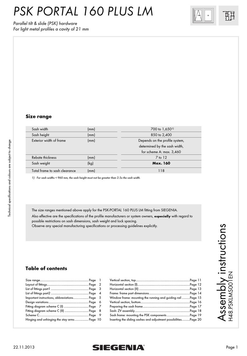
Siegenia Portal HS300 User manual

P
O
RTA
L
HS 300 lift-slide hardware
for REHAU SYNEGO profile system
with ECO PASS threshold.
H
S
30
0
Window systems
Door systems
Comfort systems
ASS
EMBLY IN
S
TR
UC
TI
O
N
S


PORTAL HS 300 REHAU SYNEGO Anschlaganleitung
03.2018 3/52H48.HSKFS0032EN
Contents
1 GENERAL INFORMATION ........................4
1.1 Target group of this documentation ......................... 4
1.2 Intended use .............................................................. 4
1.3 Safety notes............................................................... 4
1.4 Extreme weather conditions...................................... 4
1.5 Directives of the Trade Organisation for Locks and
Fittings (Gütegemeinschaft Schlösser und Beschläge
e. V.)........................................................................... 5
1.6 Handle operation...................................................... 5
1.7 Dimensions................................................................. 5
2 PROCESSING SPECIFICATIONS ................7
2.1 Size ranges................................................................ 7
2.2 Scheme versions........................................................ 7
3 OVERVIEW OF HARDWARE COMPONENTS
...............................................................8
3.1 Standard components scheme A ............................. 8
3.2 Hardware list standard components........................ 9
3.3 Thresholds................................................................10
3.4 Hardware list threshold........................................... 11
3.5 Barrier-free components.......................................... 13
3.6 Accessories for ECO PASS threshold ....................14
3.7 Hardware components for sashes up to 400 kg ..15
3.8 SOFT CLOSE hardware components..................... 16
3.9 Hook bolt gear........................................................17
3.10 Handle overview.....................................................18
3.11 Base profile.............................................................. 20
3.11.1 Height information for base profile ................................ 20
4 INSTALLATION ......................................21
4.1 Installation of corner drive......................................21
4.1.1 Milling .............................................................................. 21
4.1.2 Corner drive and connecting rod ................................... 21
4.1.3 Installation of bogie wheels............................................ 22
4.2 Gear.........................................................................23
4.2.1 Milling and drilling .......................................................... 23
4.3 Fixing gear............................................................... 24
4.4 Hook bolt gear........................................................25
4.5 Milling and drilling..................................................25
4.6 Hook bolt gear locking piece.................................26
4.7 Adjustment of hook bolt locking piece................... 27
4.7.1 Sash adjustments
.......................................................................................... 27
4.7.2 Adjusting the compression on locking piece.................. 27
4.8 Gear locking parts ..................................................28
4.9 SOFT CLOSE ........................................................... 29
4.9.1 Positioning the SOFT CLOSE trigger .............................. 29
4.10 SOFT CLOSE ........................................................... 30
4.11 Pre-tensioning the SOFT CLOSE.............................30
4.12 Inserting the SOFT CLOSE sliding sash .................31
4.13 Scheme C ................................................................32
4.13.1 Positioning locking part G............................................... 32
4.13.2 Components of the profile manufacturer ....................... 33
5 ASSEMBLY OF THRESHOLD ....................34
5.1 Sealing wedges.......................................................34
5.2 Screwing on end caps ............................................34
5.3 Drilling template ECO PASS threshold...................35
5.4 Frame corner connector..........................................35
5.5 Running rail..............................................................36
5.6 Seal REV ..................................................................36
5.7 Support rail..............................................................37
5.8 MP sealing piece.....................................................37
5.9 Sealing pad............................................................. 38
5.10 Threshold scheme D................................................39
5.10.1 Support rail B190 S107.5 ............................................. 39
5.10.2 MP EP sealing piece groove........................................... 39
5.10.3 Positioning distance plates.............................................. 40
5.10.4 Standard supporting rail ................................................. 40
5.10.5 Additional running rail and filler profile ......................... 41
5.10.6 Flat seal Scheme D.......................................................... 42
6 ACCESSORY COMPONENTS THRESHOLD43
6.1 Fixing sequence.......................................................43
7 PROFILE CROSS-SECTIONS.....................44
7.1 Horizontal cross-section .......................................... 44
7.2 Vertical cross-section bottom...................................47
7.3 Vertical cross-section top......................................... 48
8 JIGS......................................................49
9 LIABILITY ..............................................50
9.1 Intended use ............................................................ 50
9.2 Product liability........................................................ 50
9.3 Disclaimer of liability............................................... 50
9.4 Environmental protection ........................................50
9.5 Feedback on documentation..................................50

Anschlaganleitung PORTAL HS 300 REHAU SYNEGO
03.2018H48.HSKFS0032EN
4/52
1 General information
1.1 Target group of this documentation
This documentation is intended for use by specialists only. All work
described in this document is to be performed by experienced
professionals with training and practice in the assembly,
installation and maintenance of PORTAL hardware. Safe and
proper assembly of PORTAL hardware is not possible without
expert knowledge. Keep these assembly instructions in a safe
place.
1.2 Intended use
• PORTAL HS hardware for use in windows or patio doors with
profile system REHAU SYNEGO.
• Sash weight max. 300kg.
• The lift-slide PORTAL HS hardware is intended for use in fixed
buildings.
• The PORTAL HS lift-slide hardware allows the horizontal
opening and closing of doors and patio doors from profiles
for lift and slide elements.
• The lift and slide elements must be installed vertically, in no
circumstances in a sloping position.
• PORTAL HS elements may not be installed without providing
appropriate drainage and weather protection.
• Seal the threshold components and seal between the
threshold and masonry or facade observing the applicable
rules in the trade (Fachhandwerk) as set down in DIN18195
section 5 paragraph 8. 1. 5.
1.3 Safety notes
• Maintenance must be carried out on the PORTAL HS
hardware at least once a year.
• See maintenance instructions
• The hardware components described in these assembly
instructions are manufactured from steel, zinc plated and then
treated with a special process.
• The hardware components must not be used:
– in wet rooms
– in environments where the air contains aggressive or
corrosive components
– in environments where the air contains salt.
Please contact your SIEGENIA sales consultant in such
situations
• Your complete set of hardware should solely be composed of
SIEGENIA hardware components. Otherwise damage could
occur, for which we accept no liability.
• All hardware components must be mounted properly. Do not
overtighten the screws!
• The lift and slide elements may only be surface treated before
the hardware components are assembled. Treating these
surfaces at a later stage can reduce the functional capacity of
the hardware components. In such cases we are not obliged
to honour any warranty.
• When block setting, please observe technical guideline no. 3
from the German Glazing Trade [Glaserhandwerk], “Blocking
glazing units” [Klotzung von Verglasungseinheiten].
• Never use acid curing sealants as they may cause the
hardware components to corrode.
• Keep the running rail and all rebates free from dirt and debris,
especially from deposits of cement and plaster. Avoid
exposing the hardware directly to water and do not let
cleaning agents come into contact with the hardware.
• Attach the operating sticker (slide direction DIN left or DIN
right) in a visible position on the installed lift & slide sash. The
operating sticker is located in the basic carton HS- 300 T.
1.4 Extreme weather conditions
The PORTAL HS hardware must receive special protection in the
case of extreme prevalent weather conditions e.g. gales or storms
in the direct vicinity of the coast. PORTAL HS hardware must be
sealed against the permeation of foreign bodies. Foreign bodies
e.g. sand and building dust lead to an abrasive impact on the
hardware surface and to further damage to to the hardware
components. The permeation of foreign bodies must be prevented
by the application of suitable seals in the profile system or
geometric profile design. Especially in the case of externally
running sashes, it is essential to ensure that the external hardware
components must be protected against gales and storms.
Maintenance must be carried out twice a year if the hardware
components are exposed to extreme weather.
• The hardware should be freed of foreign bodies by blow out
or suction methods. Treat the bogie wheels and corner drive
on the locking side in the same way.
• Apply a non-acidic and non-resinous oil or care agent to the
surface of the hardware components.
For example:
"Korrosionsschutzspray KORRSHTZ-MITT-SPRAY-300ML
SABESTO" from Würth,
"ANTI-CORIT 5F SPRAY" from Fuchs-Schmierstoffe.
• Lubricate the drive rod of the gear via the holes in the gear
sleeve.
Verschlußstellung
Locked position
position fermée
Schiebestellung
Sliding position
position coulissante
Für Spaltlüftung Schiebeügel ca. 10 mm
vor geschlossener Position in Verschlußstellung
schalten. Nicht möglich bei Schema G!
For night vent drop sliding sash 10 mm before
locking position. Not possible with Scheme G!
Pour position aération, laisser descendre le vantail
coulissant en tournant la poignée dans la position
fermeture, et l’arrêter env. 10 mm avant la nde
course. Ne pas possible pour Schéma G!
10003
Spaltlüftungsposition
night vent positon
position ventilation à fente
Verschlußstellung
Locked position
position fermée
Schiebestellung
Sliding position
position coulissante
Spaltlüftungsposition
night vent positon
position ventilation à fente
Für Spaltlüftung Schiebeügel ca. 10 mm
vor geschlossener Position in Verschlußstellung
schalten. Nicht möglich bei Schema G!
For night vent drop sliding sash 10 mm before
locking position. Not po ssible with Scheme G!
Pour position aération, la isser descendre le vantail
coulissant en tournant la poignée dans la position
fermeture, et l’arrêter env. 10 mm avant la n de
course. Ne pas possible pour Schéma G!
1000 4

PORTAL HS 300 REHAU SYNEGO Anschlaganleitung
03.2018 5/52H48.HSKFS0032EN
1.5 Directives of the Trade Organisation for
Locks and Fittings (Gütegemeinschaft
Schlösser und Beschläge e. V.)
The directives of the Trade Organisation for Locks and Fittings
(Gütegemeinschaft Schlösser und Beschläge e. V.) provide
comprehensive information on the correct operation and
maintenance of hardware for windows and patio doors. We
deem these directives to be binding.
You can find the latest versions of the directives, in a range of
languages here:
http://www.beschlagindustrie.de/ggsb/richtlinien.asp
VHBH – Hardware for windows and patio doors
Guidelines/notes on the product and on liability
VHBE – Hardware for windows and patio doors
Guidelines and notes for end users
1.6 Handle operation
Lift and slide the sliding sash.
Lower the sliding sash. Locking position.
1.7 Dimensions
All dimensions are nominal values and include the general
tolerances (formerly "dimensional variations"). All nominal values
are given in mm.

Anschlaganleitung PORTAL HS 300 REHAU SYNEGO
03.2018H48.HSKFS0032EN
6/52

PORTAL HS 300 REHAU SYNEGO Anschlaganleitung
03.2018 7/52H48.HSKFS0032EN
2 Processing specifications
2.1 Size ranges
Profile design White Coloured
Scheme AC AC
Frame width (RAB) to 6064 to 10000 to 5064 to 6800
Frame height (RAH) 1283–2731 1283–2631 1283–2731
Sliding sash width (FBS) 738–3000 738–2500
Sliding sash height (FH) 1152–2600 1152–2500
Gear backset 37.5
Sash weight max. 400 kg
Ratio sash height (FH) / sash width (FB) > 2.25 : 1
• Furthermore, the information from REHAU SYNEGO, in particular with regard to potential
limitations in sash dimensions and sash weight, applies here
• To comply with the requirements of EN13126-16, a handle length of 225 mm must be used.
• From sash weights of 200 kg, we recommend the use of the PORTAL HS comfort gear 200 PZ - PGKB2070-52401_ or PGKB2080-
52401_.
• The components of the lift and slide element must be stored at room temperature (20°C) for 24 hours before processing.
• We recommend the use of stainless steel screws for the mounting of components to the ECO PASS threshold.
• The threshold must be shimmed at intervals of 300 mm to be pressure-tight and sound-absorbing.
• We recommend using the following elastic adhesives and sealants: e.g. from OTTO Chemie - OTTOSEAL® S 72 or from Collano
Adhesives AG - Collano® A 1970 or equivalent.
2.2 Scheme versions
DIN left or DIN right
Scheme A
Scheme C
Scheme D
Sash determination according to the specifications of the profile manufacturer
The corresponding construction drawings are available.

Anschlaganleitung PORTAL HS 300 REHAU SYNEGO
03.2018H48.HSKFS0032EN
8/52
3 Overview of hardware components
3.1 Standard components scheme A
Pic. 1: Hardware overview scheme A
10
9
12
19
13
2
3
88
3
21
15
22
6
5
18
14
17
5
5
7
7
7
7
16
11* 11*
1
4
20
see
handle selection
* Number of pieces depends on sliding sash width (FBS)
see
handle selection

PORTAL HS 300 REHAU SYNEGO Anschlaganleitung
03.2018 9/52H48.HSKFS0032EN
3.2 Hardware list standard components
Item Pieces for
scheme Material description Material number
ACD
1 1 2 Basic carton PORTALHS Scheme A consisting of: PMKB0300-10001_
1 1 1 2 Corner drive VSU HS 300 TS
2 1 1 2 Bogie wheels HS 300 TS
3 1 1 2 Brush seal
— 1 — Basic carton PORTALHS Scheme C consisting of: PMKB0310-10001_
4 — 1 — Corner drive VSU HS 300 TS
2— 1 — Bogie wheels HS 300 TS
3— 1 — Brush seal
1 — 2 Accessories HS300 PVC A REHAU SYNEGO Scheme A PMZB4380-10001_
—1—
Accessories HS300 PVC C REHAU SYNEGO
consisting of:
Scheme C PMZB4420-10001_
5 1 1 2 Locking part, top A0006 for schemes A and C
6 1 1 2 Locking part, bottom A0006 for schemes A and C
7 2 2 4 Packer HS 1 mm for schemes A and C
4 — 8 Countersunk tapping screw PH 4.8 x 60 for locking parts scheme A
— 4 — Countersunk tapping screw PH 4.8 x 80 for locking parts scheme C
8 2 4 4 Dowel pin 6 x 16 for corner drive and bogie wheels
9 1 2 2 Closing cap RAL 7001 grey
10 1 2 2 Countersunk screw PZD M5 x 13 for gear and corner drive
11 2 4 4 Top guide REHAU SYNEGO for individual component, see - dependent on FBS
8 16 16 Countersunk tapping screw B 4.8 x 65 for gear
1 2 2 Countersunk tapping screw B 4.8 x 50 for corner drive
5 10 10 Countersunk tapping screw B 4.8 x 38 for corner drive and bogie wheels
12 — 1 — Locking part G for scheme C 2nd sash
13 — 1 — Countersunk screw PH M6x 20
14 — — 1 Gasket bridge 98/12 PDIB0350-09901_
dependent on sliding sash width (FBS)
15 1 2 2 Connecting rod Ø 10 mm
Length
1015
1398
1898
FBS
738–1600
1601–2400
2401–3000
714768
PVSE0060-10001_
PVSE0050-10001_
11 1-2 2-4 2-4 Top guide REHAU is additionally required 1 piece for 1501–2500
2 piece for 2501–3000 PZUB1060-02101_
Depending on sash height (SH)
16
122
Gear
PORTALHS300 PZ
Size
170
220
260
FH
1152–1788
1789–2288
2289–2583
PGKB0010-52401_
PGKB0020-52401_
PGKB0030-52401_
122
Comfort gear
PORTALHS300 PZ 220
260
1789–2288
2289–2583
PGKB4070-52401_
PGKB4080-52401_
dependent on frame width (RAB)
17 1 1 2 Guiding rail REHAU SYNEGO
Required for use of SOFT CLOSE
Length
3500
4500
6700
7000
PPFB1040-52401_
PPFB1050-52401_
PPFB1060-52401_
PPFB1070-52401_
18 1 2 2 End cap guiding rail REHAU SYNEGO for guiding rail
from SIEGENIA PKZB0010-02102_
11—Bag stop
consisting of:
for scheme C RAL 9003 white
RAL 7035 grey
RAL 9005 black
821237
PMZB0140-021010_
831922
19 11—Stop
20 1 1 — Countersunk tapping screw B 4.8 x 70
21 1 1 — Cover cap
for anti-intruder elements
5 2 2 4 Locking part, top A0006 719213
7 2 2 4 Packer HS 1 mm 721285
4—8 Countersunk tapping screw 4.8 x 60 for locking parts scheme A 856185
—4—Countersunk tapping screw 4.8 x 80 for locking parts scheme C 900053
22 1 2 2 Anti-drill guard E 721216

Anschlaganleitung PORTAL HS 300 REHAU SYNEGO
03.2018H48.HSKFS0032EN
10/52
3.3 Thresholds
Scheme A
*Left shown, right is a mirror image
23
24
33
31
25
34*
36
2735
28 28
29 29
30
30
31
32
Pic. 2: Threshold Scheme A
Scheme C
23
24
33
31
25
34 37
36 36
27 2735 35
28 28
29 29
30
30
31
32
Pic. 3: Threshold Scheme C
Scheme D
*Left shown, right is a mirror image
23
24
33
31
26
25 27 39 39
38 38
40
4544*
41
43
28 28
29 29
30
30
31
32
42*
Pic. 4: Threshold scheme D

PORTAL HS 300 REHAU SYNEGO Anschlaganleitung
03.2018 11/52H48.HSKFS0032EN
3.4 Hardware list threshold
Item Pieces for
scheme Material description Material number
ACD
dependent on frame width (RAB)
23 1 1 1 Threshold EP R190
Length (mm)
3000
3500
4000
4500
5000
5700
6700
7000
PPBB1900-52401_
PPBB1910-52401_
PPBB1920-52401_
PPBB1930-52401_
PPBB1940-52401_
PPBB1950-52401_
PPBB1960-52401_
PPBB1970-52401_
24 1 1 1 Optional
ECOPASS flat threshold B203 R
3000
3400
4000
4500
5000
5700
6700
7000
PPBB1340-52401_
PPBB1350-52401_
PPBB1360-52401_
PPBB1370-52401_
PPBB1380-52401_
PPBB1390-52401_
PPBB1400-52401_
PPBB1410-52401_
25 1 1 2 Running rail 2/10
3500
4000
4500
5000
5700
6700
7000
PPLB6610-52401_
PPLB6620-52401_
PPLB6630-52401_
PPLB6640-52401_
PPLB6650-52401_
PPLB6660-52401_
PPLB6670-52401_
26 – – 1 Running rail 5/10
3500
4000
4500
5000
5700
6700
7000
PPLB5020-52401_
PPLB6100-52401_
PPLB5030-52401_
PPLB6110-52401_
PPLB6120-52401_
PPLB5060-52401_
PPLB5070-52401_
27
1 2 – Support rail R112
1500
2000
2500
3500
4500
6700
7000
PPZB4610-02101_
PPZB4620-02101_
PPZB4630-02101_
PPZB4640-02101_
PPZB4650-02101_
PPZB4660-02101_
PPZB4670-02101_
– – 1 Support rail B190 S107.5
1500
2000
2500
3500
4500
6700
7000
PPZB6180-02101_
PPZB6190-02101_
PPZB6200-02101_
PPZB6210-02101_
PPZB6220-02101_
PPZB6230-02101_
PPZB6240-02101_
28 2 2 2 Sealing wedge top black
orange
Standard
for use in weather bar in AMEX groove
PZUB6010-00003_
PZUB6110-00003_
29 2 2 2 Sealing wedge bottom grey Not possible with use of sealing plate PZUB6040-00003_
111Frame corner bracket REHAU SYNEGO
consisting of: PMRB0380-02101_
30 2 2 2 Sealing element R190
31 2 2 2 Seal REV for recess running rail REV
32 1 1 1 End cap, left for threshold EP
33 1 1 1 End cap, right for threshold EP
11–Sealing element MP REHAU SYNEGO left
consisting of: PMRB0412-02101_
34 1 1 Sealing piece MP links between sliding and fixed sash
35 1 1 End seal B190 Between support rail and threshold
36 1 1 Sealing pad REHAU SYNEGO between profile and sealing piece
11–Sealing piece MP REHAU SYNEGO right
consisting of: PMRB0411-02101_
37 1 1 Sealing piece MP right between sliding and fixed sash
31 1 1 End seal B190 Between support rail and threshold
32 2 1 Sealing pad REHAU SYNEGO between profile and sealing piece
––1Accessories distance plate B190
consisting of: PMZB7270-02102_
38 ––1 Distance plate B190 milling version Bag of 10
––1 Distance plate seal supporting rail Bag of 20

Anschlaganleitung PORTAL HS 300 REHAU SYNEGO
03.2018H48.HSKFS0032EN
12/52
Item Pieces for
scheme Material description Material number
ACD
––1Accessories distance plate attachment REHAU SYNEGO
consisting of: PMZB7630-02102_
39 ––1 Distance plate attachment REHAU SYNEGO Bag of 10
––1 Distance plate seal supporting rail Bag of 20
40 – – 2 Standard supporting rail
Length (mm)
1500
2500
3500
6700
PPTB0950-52401_
PPTB0960-52401_
PPTB0970-52401_
PPTB0980-52401_
41 – – 1 Filler profile EP Length (mm)
3500 PPZB6250-02101_
––1Sealing piece MP EP B190 left groove REHAU SYNEGO
consisting of: PMRB4132-02101_
42 – – 1 Sealing piece MP REHAU SYNEGO with groove left
43 – – 1 End seal B190 with groove
44 – – 1 Large sealing pad Scheme D REHAU SYNEGO left
45 – – 1 Small sealing pad Scheme D REHAU SYNEGO
––1Sealing piece MP EP B190 right groove REHAU SYNEGO
consisting of: PMRB4131-02101_
46 – – 1 Sealing piece MP REHAU SYNEGO with groove right
43 – – 1 End seal B190 with groove
47 – – 1 Large sealing pad Scheme D REHAU SYNEGO right
45 – – 1 Small sealing pad Scheme D REHAU SYNEGO

PORTAL HS 300 REHAU SYNEGO Anschlaganleitung
03.2018 13/52H48.HSKFS0032EN
3.5 Barrier-free components
Pic. 5: Accessories for ECO PASS threshold
48
50
51 52
49
56
57
55
53
33
Item Pieces for
scheme Material description Material number
AC
1 1 Basic carton PORTAL HS 300 8.5 Scheme A PMKB1300-10001_
48 1 1 Corner drive VSU HS 300 - 8.5
49 1 1 Bogie wheels HS 300 TS - 8.5
31 1 Brush seal
—1
Basic carton PORTAL HS 300 8.5
consisting of: Scheme C PMKB1310-10001_
50 — 1 Corner drive VSU HS 300 - 8.5
49 — 1 Bogie wheels HS 300 TS - 8.5
3— 1 Brush seal
12
Bag of sash parts HS barrier-free 5mm
consisting of: PMZB0850-09701_
51 1 2 Distance plate corner drive VSU size 5
52 1 2 Distance plate bogie wheels size 5
5 10 Countersunk tapping screw B 4.8 x 40 for corner drive and bogie wheels
53 1 1 Running rail 2/5
Length (mm)
3000
3500
4500
5000
5500
6700
7000
PPLB6680-52401_
PPLB6690-52401_
PPLB6700-52401_
PPLB6710-52401_
PPLB6720-52401_
PPLB6730-52401_
PPLB6740-52401_
54 1 1 Running rail 5/5
3000
3500
4500
5000
5700
6700
7000
PPLB5180-52401_
PPLB6240-52401_
PPLB5190-52401_
PPLB6190-52401_
PPLB6200-52401_
PPLB6250-52401_
PPLB5200-52401_
55 1 1 Threshold ECOPASS B190
2000
2500
3500
4500
5000
6700
7000
PPTB0380-52401_
PPTB0390-52401_
PPTB0400-52401_
PPTB0410-52401_
PPTB0420-52401_
PPTB0430-52401_
PPTB0440-52401_
11
Carton compensation rail
consisting of: 4500 PPZB0250-52401_
56 1 1 Compensation rail with seal
57 1 - ... 1 - ... Bag drill screw T-STAR 15 x 3.9 Piece number dependent on length of
threshold PZUB0600-00001_

Anschlaganleitung PORTAL HS 300 REHAU SYNEGO
03.2018H48.HSKFS0032EN
14/52
3.6 Accessories for ECO PASS threshold
Pic. 6: Accessories for threshold
58
60
59
Item Pieces for
scheme Material description Material number
AC
58 1 1
Weather bar ECOPASS B20
Length (mm)
3500
4000
4500
5000
5700
6700
PPWB0080-52401_
PPWB0160-52401_
PPWB0010-52401_
PPWB0170-52401_
PPWB0180-52401_
PPWB0020-52401_
Weather bar ECOPASS B50
3500
4000
4500
5000
5700
6700
PPWB0070-52401_
PPWB0130-52401_
PPWB0030-52401_
PPWB0140-52401_
PPWB0150-52401_
PPWB0040-52401_
Weather bar ECOPASS B90
3500
4000
4500
5000
5700
6700
PPWB0090-52401_
PPWB0190-52401_
PPWB0100-52401_
PPWB0200-52401_
PPWB0210-52401_
PPWB0110-52401_
59 1 1 Sealing plate
3500
4000
4500
5000
5700
6700
PPAB0100-52401_
PPAB0200-52401_
PPAB0070-52401_
PPAB0210-52401_
PPAB0220-52401_
PPAB0080-52401_
60 1 1 ECO PASS flat threshold
for tread plate or to cover the joint on
two-part threshold
2000
2500
3500
4500
5000
6700
PPTB0240-52401_
PPTB0250-52401_
PPTB0260-52401_
PPTB0270-52401_
PPTB0280-52401_
PPTB0300-52401_

PORTAL HS 300 REHAU SYNEGO Anschlaganleitung
03.2018 15/52H48.HSKFS0032EN
3.7 Hardware components for sashes up to 400 kg
Use only after consultation with and release by profile manufacturer.
62616162
63 6363 63
Item Pieces for
scheme Material description Material number
AC
12
Accessories carton HS400
consisting of: PMKB2340-10001_
61 2 4 Bogie wheels M
62 2 4 Short connecting rod 160 mm
63 8 16 Grub screw M8 x 16
for barrier-free elements
63 6363 63
6262
64
65
64
65
Item Pieces for
scheme Material description Material number
AC
12
Accessories carton HS400 8.5
consisting of: PMKB1340-10001_
64 2 4 Bogie wheels M 8.5
62 2 4 Short connecting rod 160 mm
63 8 16 Grub screw M8 x 16
65 1 2 Distance plate corner drive VSU size 5 carton 10 piece PZUB0380-09902_

Anschlaganleitung PORTAL HS 300 REHAU SYNEGO
03.2018H48.HSKFS0032EN
16/52
3.8 SOFT CLOSE hardware components
Pic. 7: SOFT CLOSE hardware components
1718 18
11
67 67*
68* 68*66*68 6866
11
Item Pieces for
scheme Material description Material number
AC
12
SOFT-CLOSE HH/PVC
consisting of:
Sash weight
100 kg
101 kg–200 kg
201 kg–400 kg
PSCB0120-02101_
PSCB0130-02101_
PSCB0140-02101_
66 1 2 SOFT CLOSE HH/PVC
67 1 2 SOFT CLOSE trigger
22
Accessories HS-PVC SOFT CLOSE distance plate 3
mm
consisting of: PZUB0550-02111_
68 2 2 Distance plate 3 mm
* Optional - damping function while opening is possible. A second SOFT CLOSE HH/PVC must be mounted for this purpose.

PORTAL HS 300 REHAU SYNEGO Anschlaganleitung
03.2018 17/52H48.HSKFS0032EN
3.9 Hook bolt gear
69
70
70
72
72
71
71
Pic. 8: Gear overview
Item
Pieces for
scheme Locking
cylinder Material description Material number
A
69 1 Hook bolt gear HS300 PZ
Backset
37.5
PZ
Size
220
260
Sash height FH)
1786 - 2285
2286 - 2685
PGKB9020-52401_
PGKB9030-52401_
Hook bolt gear HS300 PZ
comfort gear
220
260
1786 - 2285
2286 - 2685
PGKB9060-52401_
PGKB9070-52401_
OZ
Hook bolt gear HS300 RZ
220
260
1786 - 2285
2286 - 2685
PGKB9120-52401_
PGKB9130-52401_
Hook bolt gear HS300 RZ
comfort gear
220
260
1786 - 2285
2286 - 2685
PGKB9160-52401_
PGKB9170-52401_
RZ
Hook bolt gear HS300 RZ
220
260
1786 - 2285
2286 - 2685
PGKB9220-52401_
PGKB9230-52401_
Hook bolt gear HS300 RZ
comfort gear
220
260
1786 - 2285
2286 - 2685
PGKB9260-52401_
PGKB9270-52401_
70 2 Frame part SHG PRSB0010-10001_
71 2 Packer SHG 22.5/6 mm PGZB0210-02301_
72 2 Screen SHG REHAU SYNEGO PGZB0300-02501_
4 Countersunk screw M5 x 40

Anschlaganleitung PORTAL HS 300 REHAU SYNEGO
03.2018H48.HSKFS0032EN
18/52
3.10 Handle overview
Item Pieces Material description Colour Material number
1 Carton handle Si-line PORTAL HS 300 RAL 9003 signal white PMHB0010-50201_
consisting of: RAL 8022 black brown PMHB0010-51201_
H1 1 Handle HS 300 Si-line
H1
H3
H4
H2
EV 1 silver PMHB0010-52401_
H2 1 Rose Si-line HS 300, inside
H3 1 Cover cap Si-line HS 300
H4 1 Sliding grip Si-line
1 Carton handle Si-line PORTAL HS 300 PZ for lockable elements - with
profile half cylinder inside
RAL 9003 signal white PMHB0020-50201_
consisting of: RAL 8022 black brown PMHB0020-51201_
H1 1 Handle HS 300 Si-line
H1
H5
H4
H2
EV 1 silver PMHB0020-52401_
H2 1 Rose Si-line HS 300, inside
H3 1 Sliding grip Si-line
H5 1 Cover cap Si-line HS 300 PZ
1Carton handle Si-line PORTAL HS 300 RZ
A0089 for lockable elements - with profile half cylinder
inside
for subsequent retrofitting with RZ
RAL 9003 signal white PMHB0110-50201_
consisting of: EV 1 silver PMHB0110-52401_
H1 1 Handle HS 300 Si-line
H1
H3
H6
H3 1 Cover cap Si-line HS 300
H6 1 Rose Si-line HS 300 RZ inside
1 Cover cap RZ A0089 for lockable elements - with profile half cylinder
inside
for subsequent retrofitting with RZ
RAL 9003 signal white PMHB0060-50201_
consisting of: EV 1 silver PMHB0060-52401_
H7 1 Cover cap Si-line HS 300 RZ A0089
H1
H7
H6
1Carton handle Si-line PORTAL HS 300 RZ
inside
for lockable elements - with profile half cylinder
inside and outside only in conjunction with handle
Si-line HS 300 PZ outside
RAL 9003 signal white PMHB0050-50201_
consisting of: RAL 8022 black brown PMHB0050-51201_
H1 1 Handle HS 300 Si-line
H1
H5
H2
EV 1 silver PMHB0050-52401_
H2 1 Rose Si-line HS 300, inside
H5 1 Cover cap Si-line HS 300 PZ
1Carton handle Si-line PORTAL HS 300 PZ
outside
for lockable elements - with profile half cylinder
inside and outside only in conjunction with
handle Si-line HS 300 PZ outside
RAL 9003 signal white PMHB0040-50201_
consisting of: RAL 8022 black brown PMHB0040-51201_
H1 1 Handle HS 300 Si-line EV 1 silver PMHB0040-52401_
H5 1 Cover cap Si-line HS 300
H8 1 Rose Si-line HS 300 outside
1 Carton handle Si-line PORTAL HS 300 RZ
for lockable elements - with profile half cylinder
inside and outside only in conjunction with
handle Si-line HS 300 PZ inside
RAL 9003 signal white PMHB0130-50201_
inside A0089 consisting of: EV 1 silver PMHB0130-51401_
H1 1 Handle HS 300 Si-line
H1
H7
H6
H6 1 Rose Si-line HS 300, inside
H7 1 Cover cap Si-line HS 300 RZ A0089
1 Carton handle Si-line PORTAL HS 300 RZ
for lockable elements - with profile half cylinder
inside and outside only in conjunction with
handle Si-line HS 300 PZ inside
RAL 9003 signal white PMHB0120-50201_
outside A0089 consisting of: EV 1 silver PMHB0120-51401_
H8
H1
H5

PORTAL HS 300 REHAU SYNEGO Anschlaganleitung
03.2018 19/52H48.HSKFS0032EN
Item Pieces Material description Colour Material number
H1 1 Handle HS 300 Si-line
H7 1 Cover cap Si-line HS 300 RZ A0089
H9 1 Rose Si-line HS 300 outside
1 Carton pop up handle HS 300 inside RAL 9003 signal white PHIB0050-00201_
consisting of: RAL 8022 black brown PHIB0050-01201_
H10 1 Pop up handle HS 300 inside with 40 mm spindle
length
EV 1 silver PHIB0050-02501_
Carton pop up handle HS 300 inside RAL 9003 signal white PHIB0090-00201_
consisting of: RAL 8022 black brown PHIB0090-01201_
H11 1 Pop up handle HS 300 inside with 100 mm
spindle length
EV 1 silver PHIB0090-02501_
1 Bag of accessories HS 200/300 handle for lockable elements - with
profile half cylinder inside
consisting of:
H12 1 Square spindle ¨10 mm
H13 2 Countersunk screw M5 x ....
H14 1 Stud bolt M 6 x 8
1Bag of accessories HS 200/300 handle Length of square spindle: 100 mm
Countersunk screw M5 x 85
PMZB0250-10001_
for sash timber thickness 78 mm
1Bag of accessories HS 200/300 handle Length of square spindle: 120 mm
Countersunk screw M5 x 90
PMZB0260-10001_
for sash timber thickness 82 mm
1 Escutcheon HS 200/300 RAL 9003 signal white PHZB0030-50201_
consisting of: RAL 8022 black brown PHZB0030-51201_
H15 1 Escutcheon Si-line outside EV 1 silver PHZB0030-52501_
H16 2 Sleeve nut M 5
For handle fixation without sliding grip or
escutcheon
800287
H9
H1
H7
H10 H11
H13
H12
H14
H15
H16

Anschlaganleitung PORTAL HS 300 REHAU SYNEGO
03.2018H48.HSKFS0032EN
20/52
3.11 Base profile
If a support for the ECO PASS threshold is necessary, only base
profiles from SIEGENIA may be used for this purpose.
No warranty is assumed if other base profiles are used.
3.11.1 Height information for base profile
During assembly of the base profile, the threshold must be laid
levelly or lined, especially in the area of a potentially existent joint.
The length of the support profile must at least match the width of
the base profile.
Material description Material number
Base profile
Possible
system versions
B171
B182
B190
B194
B203
B207
Possible heights
40 mm
60 mm
80 mm
100 mm
120 mm
140 mm
160 mm
On request
Reinforcement: ECO PASS
Height
2 mm
3 mm
4 mm
PBZB0130-00006_
PBZB0140-00006_
PBZB0150-00006_
Table of contents
Other Siegenia Indoor Furnishing manuals
Popular Indoor Furnishing manuals by other brands

JWA
JWA Cobb 75101 Assembly instruction

Gautier
Gautier Galipette 839 manual

Pedrali
Pedrali MATRIX TMA instructions

BLACK RED WHITE
BLACK RED WHITE Azteca S205-SFW1K/4/15 Assembly instructions

Wholesale Interiors
Wholesale Interiors BBT6423 Assembly instructions

Safavieh Furniture
Safavieh Furniture FOX6017A quick start guide

Original Tractor Cabs
Original Tractor Cabs SUNSHADE 30481 Parts List & Assembly Instructions

Coaster
Coaster 601514 Assembly instructions

Wilson & Fisher
Wilson & Fisher MONTERRA 850091 quick start guide

WB Mfg
WB Mfg DT-45A Assembly instructions

Argos
Argos Virgo Multi Media Storage Shelf Assembly instructions

Abble
Abble 300525 quick start guide