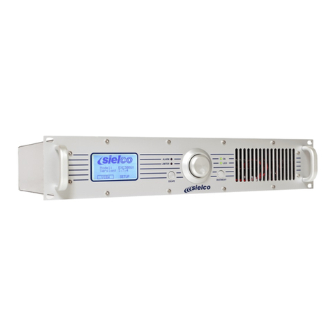
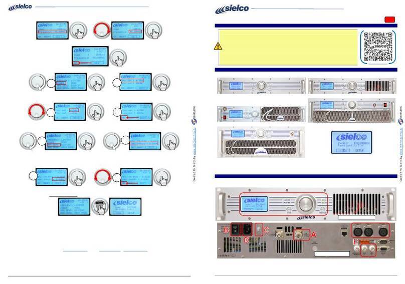
sielco EXC19 Operating instructions

Rev. 1.5 - 05/16
SIELCO srl - Via Toscana, 57/59 - 20090 BUCCINASCO (Mi) - ITALY - tel. 02 - 45713300 - www.sielco.org
EXC/RTX19
SHF BROADCAST STL
1300 ÷ 2500 MHz
USER AND MAINTENANCE MANUAL

SIELCO srl - Via Toscana, 57/59 - 20090 BUCCINASCO (Mi) - ITALY - tel. 02 - 45713300 - www.sielco.org
EXC/RTX19 - USER & MAINTENANCE MANUAL - rev.1.5 - 05/16
Page 2
CONTENTS
1R&TTE DECLARATION OF CONFORMITY (DoC).................................................3
2INTRODUCTION ...........................................................................................................4
3GENERAL DESCRIPTION ...........................................................................................5
4TECHNICALFEATURES ..............................................................................................6
4.1 TRANSMITTER REVIEW ......................................................................................6
4.2 RECEIVER REVIEW ...............................................................................................8
4.3 TECHNICAL SPECIFICATIONS ..........................................................................10
5REMOTE CONTROL FUNCTIONS ..........................................................................12
6BATTERY OR D.C. SUPPLY .......................................................................................14
7SERVICE AND MAINTENANCE ..............................................................................17
8GUARANTEE ................................................................................................................17
9SERVICE MANUAL.....................................................................................................18
8.1 TRANSMITTER INTERNAL DESCRIPTION ...............................................18
8.2 RECEIVER INTERNAL DESCRIPTION ........................................................19
10 STL MANAGING FIRMWARE..................................................................................20
10.1 INTRODUCTION ...............................................................................................20
10.2 PASSWORD ORGANIZATION ........................................................................21
10.3 FACTORY DEFAULTPASSWORDS ...............................................................22
10.4 MENU AND COMMANDS DESCRIPTION ..................................................23
10.5 TRANSMITTER MENU ...................................................................................24
10.6 TRANSMITTER SETUP MENU ......................................................................29
10.7 FACTORY MENU ..............................................................................................35
10.8 RECEIVER MENU ............................................................................................36
10.9 RECEIVER SETUP MENU ...............................................................................39
11 TRANSMITTER INTERNAL MODULES & ELECTRICAL DIAGRAMS...........43
12 RECEIVER INTERNAL MODULES & ELECTRICAL DIAGRAMS....................59

SIELCO srl - Via Toscana, 57/59 - 20090 BUCCINASCO (Mi) - ITALY - tel. 02 - 45713300 - www.sielco.org
EXC/RTX19 - USER & MAINTENANCE MANUAL - rev.1.5 - 05/16
Page 3
EU Declaration of Conformity (DoC)
Prot. 16/105/2016
We, SIELCO s.r.l, via Toscana 59 - 20090 - BUCCINASCO (MILANO) - ITALIA
declare under our sole responsibility that the product:
Apparatusproduct: STL Audio Radio Link analog transmitter and receiver
tradename: SIELCO or SIEL
type or model: EXC19 and RTX19
withthe variants:
EXC19/13, EXC19/15, EXC19/16, EXC19/17, EXC19/18, EXC19/23, EXC19/24
RTX19/13, RTX19/15, RTX19/16, RTX19/17, RTX19/18, RTX19/23, RTX19/24
To which this declaration relates is in conformity with the essential requirements and other
relevant requirements of the R&TTE Directive (1999/5/EC).
The product is in conformity with the following standards and/or other normative documents:
HEALTH & SAFETY (Art. 3(1)(a)): EN 60215: 1989+A1 : 1992+A2 : 1994
EMC (Art. 3(1)(b)): EN 301 489-1 V1.9.2, EN 301 489-9 V1.4.1
SPECTRUM (Art. 3(2)): EN 300 454-2 V1.1.1
OTHER (inc. Art. 3(3) and voluntary specs: notapplicable
Limitationofvalidity(ifany) Equipment Class 2, subject to restriction of use
Supplementaryinformation:
Notifiedbody involved: 2051 - NEMKO SpA, via Del Carroccio, 4 - Biassono (MB) - Italy
Technicalfile heldby: SIELCO Srl, via Toscana 59 - 20090 Buccinasco (MI) - Italy
Signed for and on behalf of:
Placeof issue: Date of issue Name,function, signature
(yyyy/mm/dd) ing.SalvatoreCosentino
Buccinasco- Italy 2016/05/05 SIELCO technical Manager

SIELCO srl - Via Toscana, 57/59 - 20090 BUCCINASCO (Mi) - ITALY - tel. 02 - 45713300 - www.sielco.org
EXC/RTX19 - USER & MAINTENANCE MANUAL - rev.1.5 - 05/16
Page 4
EXC/RTX19
BROADCAST STL FAMILYSERIES
SHF 1300 ÷ 2500 MHz
INTRODUCTION
TheEXC/RTX19series stls are the result of experience gained by SIELCO (formerly SIEL)during
years of producing FM broadcast equipment, transmitters, stl and stereo encoders.
These radio links were specifically designed to comply with the latest international standards
and the requirements of advanced broadcasters, meeting tighter specifications than usually
required, at an affordable cost.
Great care was spent into producing a Hi-Fi-quality modulated signal, with low residual noise
and distortion. The RF signal is also free from spurious and harmonic components to a higher degree
than required by CCIR, European, USA and most other national standards.
To obtain this outstanding performance, SIELCO strongly recommend to rely on qualified
personnel to install and verify the equipment which makes up the radio station, i.e. the stl, the
transmitters and the power amplifiers, the corresponding antennas, cables and connectors. This will
assure to achieve the best performance and stability in time.
Tothis aim, SIELCOespecially recommendthattheir equipment shouldnot betamperedwith by
unskilled personnel and its after-sale service is available to customers for any technical problem.
Before proceeding to installation, please carefully read at least the general installation part of this
manual, to gain confidence with the equipment.
These equipment are very stable and changes to the internal pre-setting other than frequency and
few other options are not usually required but, if they are, once again they must be done by skilled
personnel, with proper instrumentation and service documentation. Improperly tampering with the
settings may harm the apparatus or jeopardize the guaranteed performance.
THIS EQUIPMENT COMPLIES WITH ALL RELEVANT EMI/EMC AND SAFETY
REQUIREMENTS, ETSI EN300454-1/2 AND ETS301489-01/11 STANDARDS.
NO INTERNAL ADJUSTMENT OR PRESETTING IS REQUIRED DURING NORMAL
OPERATIONS. THEAPPARATUS SHALLBEPROPERLYEARTHEDAND BE OPERATED
WITH ALL THE COVERS CLOSED TO PREVENT ELECTRICAL HAZARDS AND
COMPLY WITH EMC STANDARDS.
——— MAINS VOLTAGE MAY KILL ———

SIELCO srl - Via Toscana, 57/59 - 20090 BUCCINASCO (Mi) - ITALY - tel. 02 - 45713300 - www.sielco.org
EXC/RTX19 - USER & MAINTENANCE MANUAL - rev.1.5 - 05/16
Page 5
GENERAL DESCRIPTION
The EXC19 transmitter and its companion RTX19 receiver are the core of a high quality,
synthesised studio-to-transmitter link (stl), to be used for broadcast repeaters in conjunction with
any standard FM or AM transmitter. Design of this apparatus derives from the extablished EXC/
RTX18 series stl whose main circuitry is still extensively used here with new controllers and more
advanced oscillators in a modern and attractive "slim" case.
They allow the reception of mono or stereo signal and its retransmission without using any
additional stereo-coder on the receiving end: in both cases the LF output signal from the receiver
must be sent to the stereo input (linear or not pre-emphasised) of the local FM rebroadcast
transmitter.
The stl is built for several different frequency slots in the SHF range. While the exterior
cabinet, the controls, the basic circuitry and the performances are the same, some internal
components vary as required to cover this wide frequency band. Usually these components are
the local oscillator, the power amplifier and the input/output filters
In the whole SHF range the internal modules are the same, with some tuning adjustments.
The factory adjusted frequency slots are 10 to 50 MHz wide and must be specified in the order.
In the preset sub-range, the frequency and power of the transmitter may be freely changed on
the field. The receiver on the contrary requires some more adjustment for wider frequency
displacement: in fact the adoption of a very narrow, low loss microwave input filter permitted
to achieve the best possible rejection of interfering signals in the band at the expense of some
frequency agility. So nearly 8-10MHz may be used without any retouching but wider variation
up to 50-60MHz will require retuning of the input filter.
Being the apparatuses completely digitally controlled, they are extensively on field program-
mable by front panel or remotely in every respect. The alphanumeric display permits easy and
accurate metering, adjustment and continuous monitoring of modulation levels, power, operation
and internal parameters. All these information are externally available on the same RS232 I/O port
that may be used to remotely control the transmitter. In addition to the serial I/O, some signals and
controls are available on a parallel I/O socket for easy interfacing with others analog controllers
or supervisory systems. A powerful 3-levels password management permits a very high degree
of security and privacy as may be required in different situations.
The LF input and output levels are precisely adjustable over a broad range, by means of
0.5dB stepwise variable attenuators. The transmitter has also an auxiliary input, specifically
designed for RDS and SCA encoders. A modulation monitor output permits to control other
transmitters or STL's with the same internally processed high-quality mpx signal. Furthermore,
the system is optimised to be compatible with external digital companding encoder/decoders
and to provide RDS and SCA signals, with almost no attenuation.
Optional top-quality stereo encoder/decoder boards may be factory installed on the transmitter/
receiver or field retrofitted with minimum required technical skill. The powerful internal software
and monitoring functions recognise their presence and enable the functions. A universal switch-
mode power supply permits operation in the extended 95-250 Vac range with no intervention and
a 24 V back-up battery input is provided too.

SIELCO srl - Via Toscana, 57/59 - 20090 BUCCINASCO (Mi) - ITALY - tel. 02 - 45713300 - www.sielco.org
EXC/RTX19 - USER & MAINTENANCE MANUAL - rev.1.5 - 05/16
Page 6
TECHNICAL FEATURES
TRANSMITTER REVIEW
Thetransmitter and receiver set arefitted inthe samesized cabinet andare verysimilar on thefront
view.Aventilationgridcharacterizestheformertopermita lightaircirculationtoenhance heatexchange
in the power stage.
Both the equipment are clean and easy to control from the front panel through a single knob.
The wide alphanumeric display and a simple self-explanatory menu drives navigation through the
various options. A single fast push on the jog knob acts as an "Enter" or confirmation while pushing
for a longer time is interpreted as "Escape".
Some leds signal at a glance proper functioning and warning states. Two red led signal warning
status, "Alarm" and "Limiter". A bi-stable yellow/green led signals "On the air" while a fourth
one signals "PLL Lock": both these two should be green in correct operation.
A RF Monitor output connector is located also on the front panel for easy test on the field

SIELCO srl - Via Toscana, 57/59 - 20090 BUCCINASCO (Mi) - ITALY - tel. 02 - 45713300 - www.sielco.org
EXC/RTX19 - USER & MAINTENANCE MANUAL - rev.1.5 - 05/16
Page 7
+
2A max
3 Signal -
2 Signal +
1 Ground RIGHTAES/EBU LEFT
MADE IN ITALY
MPXMONITOR
MODULATION
AUX
RS232
REMOTE
2051
24V
RF OUTPUT
50 OHM
POWER
110-240V~
50-60Hz 70VA
FUSE T 2 A L 250V
All equipment inputs and outputs but RF monitor are allocated on the rear panel. They are:
-Themains supply IEC320-type outlet whichincorporates the fuseholder, themains switch, an
additional earth screw for system earthing and a 24V-battery backup socket pair.
-The RF antenna connector, N-type
-The L & R audio channels input sockets on balanced XLR-type connectors (L input is used
only with internal Stereo Encoder option).
-The wide-band external processed stereo or composite signal input on a grounded
unbalanced BNC connector
-A frequency limited (20k
÷
100kHz) auxiliary channel input on a grounded, unbalanced BNC
connector for a RDS or SCA signal.
-A LF modulation output for monitoring, RDS external synchronisation or re-broadcasting
purpose, BNC-type
-A RS232 Dsub9 female remote serial control port, inverted wired.
-A parallel control port, Dsub9 male type
No internal or external preset is needed to correctly perform on 110 - 240V~ mains range
Transmitter block diagram

SIELCO srl - Via Toscana, 57/59 - 20090 BUCCINASCO (Mi) - ITALY - tel. 02 - 45713300 - www.sielco.org
EXC/RTX19 - USER & MAINTENANCE MANUAL - rev.1.5 - 05/16
Page 8
Like the Transmitter, the Receiver front panel accommodates the single control knob, the
display, four leds for immediate status control and a single output connector for IF monitoring.
Here too regular operation is signallized by green leds: "PLL Lock" and "Field". This latter
is a bi-stable and lights in yellow when RF field is too low or absent. As in the Transmitter red
leds signals improper operation. The first one, "Modulation", is activated by low or absent
modulation; the last one is the general "Alarm" led.
RECEIVER REVIEW

SIELCO srl - Via Toscana, 57/59 - 20090 BUCCINASCO (Mi) - ITALY - tel. 02 - 45713300 - www.sielco.org
EXC/RTX19 - USER & MAINTENANCE MANUAL - rev.1.5 - 05/16
Page 9
FUSE T 2A L 250V
POWER
MONITOR
110-240V~
50-60Hz 40VA 50 OHM
RF INPUT
1 Ground
2 Signal +
3 Signal -
STEREO
RIGHT LEFT MONO
RS232
2051
MADE IN ITALY
REMOTE
MPX+MPX-
10-75000 Hz
N+1 CONTROL
+
1A max
24V
Receiver rear panel
Receiver block diagram
The Receiver I/O connectors on the rear panel are:
-Themainssupply IEC320-type outlet which incorporates thefuse holder, the mainsswitch, an
additional earth screw for system earthing and a 24V-battery backup socket pair.
-The RF antenna connector, N-type
-The main composite signal output (Mpx+, Mpx-) on two BNC-type connectors in antiphase,
permitting direct drive of two separate transmitters or one in balanced mode.
-Abuffered LF monitor, BNC-typeconnector thatmay beinternally connectedas an additional
composite or wide-band or mono signal output.
-The filtered/de-emphasised mono signal on a balanced male XLR-type connector.
-The L & R audio channels output sockets on balanced XLR-type connectors (only with
internal Stereo Decoder option).
-A RS232 Dsub9 female remote serial control port, inverted wired.
-A parallel control port, Dsub9 male type
-An optional "N+1" parallel control port on a DB9 female type connector.

SIELCO srl - Via Toscana, 57/59 - 20090 BUCCINASCO (Mi) - ITALY - tel. 02 - 45713300 - www.sielco.org
EXC/RTX19 - USER & MAINTENANCE MANUAL - rev.1.5 - 05/16
Page 10
TECHNICALSPECIFICATIONS
-Factory preset frequency ranges
1350÷1375 Mhz 1370÷1390 Mhz
1429÷1433MHz 1510÷1530MHz
1660÷1670MHz 2367.5÷2372.5MHz
2440÷2.450MHz 2468.1÷2483.3MHz
Other sub-ranges on request
-Modulation: FM, 75 kHz peak dev.
180kF3E mono
256kF3E stereo
-Synthesis step: 25kHz
-Composite Mpx output response:
15 Hz ÷ 67 kHz +0.1/-0.5dB
<-6 dB @ 100 kHz
<-20 dB @ 125 kHz
-Monitor output wide-band response:
15 Hz ÷ 100 kHz +0.1/-1.5dB
-3 dB typ. @ 125 kHz
-6 dB typ. @ 160 kHz
-Mono/stereo decoded response:
30 Hz ÷ 15 kHz ±0.2dB
-S/N ratio (30÷20000Hz rms):
>75 dB, 80 typ. mono
>72 dB, 76 typ. stereo
-Modulation distortion (100% dev.):
@ 1 kHz/
mono ≤0.1% 0.05% typ.
stereo, 1ch ≤0.30% 0.20% typ.
@ 30÷7500 Hz
mono ≤0.25% 0.12% typ.
stereo, 1ch ≤0.30% 0.20% typ.
-Stereo crosstalk (typical):>50 dB (400÷10000 Hz)
>40 dB (100÷15000 Hz)
-I/O lines: Alarm, RF/LF disable, Low RF field
remote control/lock
RS232 for monitoring and control
-Mains requirements:
110 - 240 V~ 50/60 Hz
24V=
-Operating temperature range:
0÷35° C recomm.
-10÷45 °C max.
EXC19 TRANSMITTER ONLY
-Frequency error: <2,5 ppM
-Frequency drift: <1 ppM/year
-RF output power: 0.5 ÷5W
-Max allowed reflected power: 2W
-RF harmonic products: <-60 dBc
-RF spurious products: <-70 dBc, -80 dBc typ.
-RF output: 50 ohm, N connector
-Audio/Mpx input level: -3.5 ÷ +12.5dBm
@ ± 75kHz deviation
-Audio/Mpx input:
10k ohm/600 ohm, bal./unbalanced
-Common mode rejection:
>50 dB, >60dB typ. (20÷15000 Hz)
-Audio input connectors: female XLR type
-Auxiliary channel input level:
-12.5 ÷ +3.5dBm @±7.5 kHz dev.
-24 ÷ -8dBm @±2 kHz dev.
-Aux channel input: 10k ohm / BNC-type
-Monitor LF output:
0 ÷ +10 dBm @ ±75kHz dev.
-Pre-emphasis time constant: 0/50/75 µs ±2%

SIELCO srl - Via Toscana, 57/59 - 20090 BUCCINASCO (Mi) - ITALY - tel. 02 - 45713300 - www.sielco.org
EXC/RTX19 - USER & MAINTENANCE MANUAL - rev.1.5 - 05/16
Page 11
-S/N noise ratio (30÷20000Hz rms):
>77 dB, 82 typ. (mono)
>74 dB, 77 typ. (stereo)
-Modulation distortion, 30÷15000 Hz:
<0.02% @ 75kHz dev.
-Stereo crosstalk: >50 dB (100÷5000 Hz)
>45 dB (50÷15000 Hz)
-Audio channels response:
30 Hz ÷ 15 kHz ±0.1dB
-Out of band audio attenuation:
>50 dB @ F≥19 kHz
-Deviation limiter: 0 ÷ +7.1 dB, adjustable
-Mpx composite response:
10 Hz÷100kHz ±0.1dB
-Auxiliary channel response:
10÷ 100 kHz ±0.2dB
-I/O lines: RF disable, RF power, On-the-Air,
Alarm.
RS232 control and monitoring
-Mains absorption: 45 Wmax @ 110 - 240 V~
-Battery absorption:≤1.8A @ 24 Vdc (Po= 5W)
-Dimensions, without handles: 19" 1 un. std. rack
483 x 43.5 x 320 mm
RTX19 RECEIVER ONLY
-Noise figure: ≤9 dB
-Image frequency rejection: ≥60 dB 70 typ.
-Dynamic selectivity: >+10dB typ @ δF=300 kHz
>+35dB typ @ δF=500 kHz
>+45dB typ @ δF=1.0 MHz
-AM suppression: >45 dB
-Usable input level: -90 ÷ -10dBm
(7µV÷70mV)
-Sensitivity (typical): Sin= -90dBm (7µV) mono
(S/N=60dB) Sin= -70dBm (70µV) stereo
-IF monitor output: 10.7 MHz / 0dBm
-Wide-band demodulated output response:
15 Hz ÷ 120 kHz +0.1/-3dB
-Wide-band demodulated output level: +6dBm
-MPX output level: -1.5 ÷ +12 dBm,
0.5dB/step
-Mpx output response:
15 Hz ÷ 67 kHz +0.1/-0.5dB
-mono or stereo decoded response:
30 Hz ÷ 15 kHz ±0.1dB
-Out-of-band mono or stereo audio response:
>50 dB @ F≥19 kHz
-De-emphasis time constant: 0/50/75µs ±2%
-S/N ratio (30÷20000 Hz. rms):
>72 dB, 76 typ. mono
>70 dB, 73 typ. stereo
-Modulation distortion @ 1kHz / 100% dev.:
mono ≤0.1% 0.05% typ.
stereo, 1ch ≤0.30% 0.20% typ.
-Stereo crosstalk: >50 dB (100÷5000 Hz)
>45 dB (50÷15000 Hz)
-I/O lines: LF disable, Low RF field,
Alarm.
RS232 control and monitoring
-Mains absorption: 15 Wmax @ 110 - 240 V~
-Battery absorption: ≤0.4A @ 24 V=
-Dimensions, without handles: 19" 1 un. std. rack
483 x 43.5 x 320 mm

SIELCO srl - Via Toscana, 57/59 - 20090 BUCCINASCO (Mi) - ITALY - tel. 02 - 45713300 - www.sielco.org
EXC/RTX19 - USER & MAINTENANCE MANUAL - rev.1.5 - 05/16
Page 12
REMOTE CONTROL FUNCTIONS
Both the Stl transmitter and receiver are completely presettable and controllable by the front
panel keyboard and display. The same functions are remotely possible through the serial RS232
port, which is located on the rear of each equipment. To control the equipment is anyway
required some purposely developed software which is not available at the present as a standard
option. Some simple demonstration program may be given only as a start point to development.
In addition to the serial port, a parallel one is provided on the rear, on which are wired some
signal and control wires. Both the 2 ports are described in the following paragraphs.
RS232 port
The RS232 port manages only Tx, Rx and Return data signals, with no handshake. Being the two
former signals inverted wired to the port, it needs a simple straight wired serial cable with
appropriate connectors to connect to a PC. Usually a female DB9 or DB25 female goes to the PC
port and a male DB9 connector at the transmitter end. Appropriate software is needed for
communication: simple tests may be performed with standard Windows "Hyperterminal". Do not
connect the cable with either transmitter or PC on.
Parallel remote control port
This port accommodates some lines for simple direct control / monitor on a DB9 male connector.
Many lines may be optionally assigned to differnt functions and logic polarity may be reseversed
from a dedicate setup menu. Default assignation is:
TRANSMITTER:
-Pins 1, 5, 8 Ground.
-Pin 2, On The Air output. Open collector transistor circuit with a resistive pull-up: a +12V/
10kΩsignals that the transmitter delivers substantial RF power. It is not granted that the
output power is exactly as preset.
-Pin 3, Direct power output. A signal proportional to direct power is present, with a pseudo
square law. Range is 0-5Vdc / 1kΩimpedance. Full power voltage usually ranges 3,5 to 4 V.
-Pin 6, RF enable input. Base input of a common emitter transistor with a resistive pull-up.
A shorted circuit to ground disables RF. Maximum voltage and current available are roughly
+10V and 1mA.
-Pin 7, Alarm output. Open collector transistor circuit with a resistive pull-up: logic low
signal means alarm condition. Correct functioning is signalled by +12V with10kΩ
impedance. Maximum current sinking capability <10mA.
-Pins 4 & 9: future upgrades

SIELCO srl - Via Toscana, 57/59 - 20090 BUCCINASCO (Mi) - ITALY - tel. 02 - 45713300 - www.sielco.org
EXC/RTX19 - USER & MAINTENANCE MANUAL - rev.1.5 - 05/16
Page 13
RECEIVER:
-Pins 1 & 5 Ground.
-Pin 2, “modulation ok” output. Open collector transistor circuit with a resistive pull-up:
a low logic state signals modulation is present on the received signal. On the contrary, a
high logic state, + 12V / 10kΩ, warns on modulation loss. As alternate function the pin
may be assigned to signal “remote lock”status.
-Pins 3 & 8, “field good”. The insulated contacts of a relay are wired to these pins: the
relay is default driven by the received RF. When the field trespass the preset threshold, the
relay is excited. The contacts may be chosen through an internal bridge to be "normally
open (n.o.)" or "normally closed (n.c.)". Factory default is "n.o.". Alternatively the relay
may be assigned to “Alarm”
-Pin 6, "LF disable" input. Base input of a common emitter transistor with a resistive pull-
up. A shorted circuit to ground disables main LF outputs. Maximum voltage and current
available are nearly +10V and 1mA. Alternate function is “Remote lock”: when choosen,
a shorted circuit disables front panel setup functions.
-Pin 7, Alarm output. Open collector transistor circuit with a resistive pull-up: a logic low
signal means alarm condition. Correct functioning is signalled by +12V with10kΩ
impedance. Maximum current sinking capability <10mA. This pin may be alternatively
assigned to signal “Field good”
-Pins 4 & 9: future upgrades
Transmitter serial and parallel
remote control I/O ports
Receiver serial and parallel
remote control I/O ports

SIELCO srl - Via Toscana, 57/59 - 20090 BUCCINASCO (Mi) - ITALY - tel. 02 - 45713300 - www.sielco.org
EXC/RTX19 - USER & MAINTENANCE MANUAL - rev.1.5 - 05/16
Page 14
BATTERY OR D.C. SUPPLY
The EXC/RTX19 include a low voltage d.c. power supply input with battery management,
to permit continuous d.c. power supply or back-up in case of mains failure. This input, whose
nominal voltage is 24 V negative grounded, accepts a dc supply which may range 22 ÷ 28 V
in absence of mains supply. It delivers a regulated +27.6V to permit battery charging, when
mains supply is present.
Front panel switch do not acts on d.c. supply, which is always on when applied to its
terminals on the rear panel. There is no switch in series to this supply but only a diode and a
self-reset fuse to protect from polarity reversal.
Voltage higher than 28Vdc applied to or current sunk from this input for different
purpose than battery charging may seriously impair the equipment power supply.
Notes on battery and wiring
Any kind of battery may be used, provided it has the correct voltage ( 24 V, nominal) and
an adequate capacity. Price / performance considerations may suggest plumb batteries, regular
or sealed.
We suggest using sealed batteries for small systems, 20 to 40 A/hour rated. Higher capacities,
like 40 ÷ 100 A/hour and more, may be achieved at low cost from car-type batteries: in this
case always install the batteries in a well vented place, because acid gas produced during
battery charging may damage the electronic equipment.
EXC19 and RTX19 battery inputs may be wired together to the same battery array, provided
they both are internally preset to 27.6V, as regular. In this case the power supplies appear to
be in parallel (with some redundancy) and they both charge the battery array at a higher rate.
Plumb batteries are usually made up to 12 V nominal voltage, so two batteries are required
in series. Wire them with proper section wire: 1 sq. mm is usually enough to connect them to
the transmitter and/or the receiver; bigger sections may be used in case of long wiring.
Install batteries capable of sustaining the system for the maximum foreseen period of
mains failure. Avoid to completely discharging the batteries or permanent damage may
occur to them. Even if the battery manager disconnects the battery when the voltage is
lower than 22V, a small test current, nearly 10-15mA is sunk by the circuitry in absence
of mains power. This current is capable to deeply discharge the battery array in case of
prolonged mains absence. Always remove the battery array if the system is off-line

SIELCO srl - Via Toscana, 57/59 - 20090 BUCCINASCO (Mi) - ITALY - tel. 02 - 45713300 - www.sielco.org
EXC/RTX19 - USER & MAINTENANCE MANUAL - rev.1.5 - 05/16
Page 15
Battery life
A discussion of correct installation and maintenance of the battery system goes beyond the
purpose of this manual: we suggest not to underestimating the problem and to refer to specialised
literature and to the suggestions of qualified battery manufacturers.
Our advises may be summarised in the followings:
-Use batteries whose capacity is at least 2.5 ÷ 10 times higher than the maximum expected
power absorption, on prolonged mains loss.
-Never permit batteries to undergo below minimum safe voltage, on prolonged discharges.
Following these rules, battery life expectation may range from 2 to 5 years, depending on
duty factor and temperature (low temperature decreases the capability but increases the life).
Back-up and recharge time
An estimate of the backup time, i.e. the capability of the batteries to power up the equipment
in case of mains failure, may be done by considering that:
-The manufacturers usually specify the nominal capability of a battery, discharged in a
period of 10 or 20 hour.
-For discharge faster than 10 hour, the capability will be reduced. For slower discharges,
it may be increased. Typical values are 70 % for discharge in 2 hours and 110 %, for
discharges in 50 hours.
-The capability will diminish with time and usage: typical derating may be 10÷30 % /
year.
-Taking in count all previously said, with a real capability which is derived from the
nominal one with the suggested corrections, the backup time is given by the capacity in
A/hour divided the absorption of the equipment which makes up the load, in A.
-The supplied recharge current delivered by the equipment is nearly 0.5-1.0 A by the
EXC19 and 1.5-2.0A by the RTX19, when the batteries are almost discharged.
-While the charge voltage is roughly constant, the charge current is not. The charge time
may be rather long, even some day, especially in case of deep discharge and heavy load
on the equipment.

SIELCO srl - Via Toscana, 57/59 - 20090 BUCCINASCO (Mi) - ITALY - tel. 02 - 45713300 - www.sielco.org
EXC/RTX19 - USER & MAINTENANCE MANUAL - rev.1.5 - 05/16
Page 16
As reference we give the following table with an estimate of the maximum backup time for
some combinations of equipment and batteries, which is valid only for new, fully charged
batteries. The current absorption for EXC19 transmitter is typical for a 2400MHz version @
5W output power.
EXC19 RTX19 EXC19 + APPARATUS
RTX19 TYPE
Mean absorbtion 1.8 0.45 2.25 [A]
Backup time with
20 A/hour battery 11 44 9[hour]
Backup time with
40 A/hour battery 23 95 19 [hour]
Backup time with
100 A/hour battery 55 250 47 [hour]

SIELCO srl - Via Toscana, 57/59 - 20090 BUCCINASCO (Mi) - ITALY - tel. 02 - 45713300 - www.sielco.org
EXC/RTX19 - USER & MAINTENANCE MANUAL - rev.1.5 - 05/16
Page 17
SERVICE AND MAINTENANCE
The STL Transmitter is cooled by a light forced air flux and may require some internal cleaning
after some years of continuos service internally and especially on the ventilation fan. A soft brush
or compressed air is recommended to this aid, after having removed the apparatus from mains. The
Receiver is natural convection cooled and do not requires any internal cleaning. Both the apparatus
may be externally cleaned with a wet cloth always after they have been removed from mains.
It is very important to install the apparatus on a stable stand/rack, in such a way to permit good
ventilation. Other than this, because of the high-quality materials used in their manufacture, if it
is correctly installed in an adequately protected environment it will not require special
maintenance for quite some time.
After a few years of continuous service, it is recommended that the apparatus is overhauled in
the factory or in a specialised laboratory, where the characteristics can be checked against the
initial ones and re-calibration can be done when needed. Internal presets are extremely stable and
we don not recommend tampering with them if not in specially equipped laboratories.
Never change the internal calibrations to avoid altering the transmitter and receiver
declared performances.
It is especially important that the power supply be over-hauled when the apparatus have been
working for years at high temperatures, over 30 / 35 °C. Ventilation fan in the Transmitter may also
require to be replaced after 20-30000 hours.
GUARANTEE
Like all SIELCO's solid state equipment, the STL carries a one-year guarantee on all their
components with the exclusion of the final RF power transistor, which may be damaged by faulty
output connections.
This guarantee is null and void if the apparatus is tampered with or if failure is due to improper
use, wrong installation or external causes, such as mains overvoltage.
This guarantee covers work done exclusively in our laboratories and in those of our agreed
representatives.
The goods shall be delivered carriage prepaid to the laboratory and shall bereturned freight
forward.
This guarantee does not cover any consequential damage due to non-operation or faulty
operation.

SIELCO srl - Via Toscana, 57/59 - 20090 BUCCINASCO (Mi) - ITALY - tel. 02 - 45713300 - www.sielco.org
EXC/RTX19 - USER & MAINTENANCE MANUAL - rev.1.5 - 05/16
Page 18
SERVICE MANUAL
THIS SECTION IS ONLY AIMED TO GENERAL EXPLANATION, REFERENCE AND
SERVICE PURPOSE BY SKILLED PERSONNEL. AS EXPLAINED IN THE PREVIOUS
SECTIONS, INTERNAL ADJUSTMENTS ARE NOT REQUIRED DURING NORMAL
OPERATION. TAMPERING WITH INTERNAL SETTINGS VOIDS THE WARRANTY,
MAY HARM THE APPARATUS AND JEOPARDIZE THE GUARANTEED PERFORMAN-
CE. COMPONENT VALUES SHOWN MAY ACTUALLY VARY FOR PRODUCTION
REQUIREMENTS.
DUE TO THE TECHNOLOGY USED, MOST MODULES AND ESPECIALLY THOSE
IN SMT ARE NOT INTENDED TO BE REPAIRED IN CASE OF FAILURE AND MUST
BE REPLACED WITH NEW ONES.
INTERNAL TRANSMITTER DESCRIPTION
The EXC19 transmitter comprises 7 internal modules, as can be seen in the drawing “General
view” and in the "General wiring diagram", both comprised in this manual. Some of these
modules vary according to the preset frequency range.
-The CPU controller and display board
-The LF and RF control main-board
-The stereo-encoder module (optional)
-The synthesised oscillator module, 1300 ÷ 2600 MHz version
-The RF power amplifier, 1300 ÷ 2600 MHz
-The regulated power supply
-The auxiliary regulator and battery charger board
For the detailed description of each module on the following pages, refer to the corresponding
electrical diagram, in the relevant section of the manual.
WARNING !
I

SIELCO srl - Via Toscana, 57/59 - 20090 BUCCINASCO (Mi) - ITALY - tel. 02 - 45713300 - www.sielco.org
EXC/RTX19 - USER & MAINTENANCE MANUAL - rev.1.5 - 05/16
Page 19
INTERNAL RECEIVER DESCRIPTION
The RTX19 receiver comprises as much as 8 internal modules, as can be seen in the drawing
“General view” and in the "General wiring diagram". As in the case of the transmitter, some
of these modules vary according to the preset frequency range. All possible modules are:
-The regulated power supply
-The auxiliary regulator and battery charger board
-The CPU controller and display board
-The synthesised local oscillator module, 1400 ÷ 2600 MHz version
-The LNA, FI amplifier and FM demodulator board
-The LF interface and control main-board
-The RF input filter
-The stereo-decoder module (optional)
The first 4 modules are identical to those of the transmitter and their description is not replied.
For the rest of them refer to the corresponding electrical diagram, in the relevant section of
the manual.
While the CPU control board is identical to that of the transmitter, the internal microcontroller
incorporates its own different firmware for this task.

SIELCO srl - Via Toscana, 57/59 - 20090 BUCCINASCO (Mi) - ITALY - tel. 02 - 45713300 - www.sielco.org
EXC/RTX19 - USER & MAINTENANCE MANUAL - rev.1.5 - 05/16
Page 20
TX/RX19 - rev. 1.00
BROADCAST STL MANAGEMENT FIRMWARE
INTRODUCTION
A modern microcontroller (µCU) controls all internal functions of the EXC/RTX19 stl family as required
by customer's preset, supervises the equipment and manages all the necessary tasks of measure, process
and remote control.
The internal microcontroller software or "firmware", is periodically revised to correct possible
defects or to incorporate new functions and peripheral module control. The firmware updating can
be done only at factory or at specially equipped laboratories by flashing a new progam over the old
one on the microcontroller without substituing any component. A special interface is required.
The EXC19 stl transmitter and the RTX19 receiver adopt different, incompatible firmware, because
of the different tasks required. Hence, particular care must be paid to install a correctly programmed
µCU for the transmitter or the receiver (TX19 or RX19 firmware).
With the exception of some specific transmitter or receiver menus, the user interface is identical for
both. The same applies to most of display functions and the operating system. As far as possible
great care was spent to simplify the software operations, to make it intuitive and not to change the
basic functions in case of new added features.
NOTE: new software releases may be provided to take advantage of experience and to add new
functions. Factory supplied equipment incorporate the latest stable firmware available at the time
being. The customer of an equipment which do not incorporate the latest release do not need to
change it unless there are explicit functional defects or needing of the new functions added.
SIELCO WILL NOT IN ANY CASE BE RESPONSIBLE OF POSSIBLE DAMAGES DUE TO
THE DIFFERENT OPERATING MODE OF THE EQUIPMENT DUE TO CHANGE OF ITS
INTERNAL CPU AND FIRMWARE RELEASE. WARRANTY, IN THIS CASE, IS LIMITED
TO SUBSTITUTION OF THE CPU CONSIDERED AS NOT-FUNCTIONAL OR TO ITS
REFUND.
This manual suits for next models
1
Table of contents
Other sielco Transmitter manuals
Popular Transmitter manuals by other brands
CYP
CYP CH-352TX Operation manual

RKI Instruments
RKI Instruments 65-2320RK Operator's manual

Audio Technica
Audio Technica ESW-T211 Installation and operation

Becker
Becker Centronic EC548 Plus Assembly and operating instructions

Shure
Shure ADX1M user guide

Becker
Becker Centronic SunWindControl SWC442-II Assembly and operating instructions
