sielco EXC GX Series Operating instructions

SIELCO Headquarter:
Via Toscana, 57/59 - 20090 - Buccinasco (MI)
Tel. +39-02-45713300 Fax +39-02-45713351
FM super-compact transmitter series
User and maintenance manual
Version 1.0 – 01/2019

User Manual Page 2 of 71
Preliminary notes
We used the utmost care in making a complete manual with detailed, precise, and updated information; however, the contents herein
cannot be regarded as binding towards our company.
SIELCO, in their constant commitment to improve the quality of their products, reserve the right to vary the device’s technical features
without prior notice. For updates, please visit our web-site www.sielco.org or contact our local dealer or agent.
The manufacturer will not be held responsible for any consequences caused by errors or improper handling and over which he has no
direct control.
The described options may vary from model to model to meet the specific requirements of our customers.
All rights reserved. No part of this document may be reproduced in any form or by any means, including recording or photocopy without
Sielco’s prior written authorization.
Via Toscana 57/ 59 - 20090 Buccinasco (Milano) - Italy
Tel +39-02-45713300
Fax +39-02-45713351
E-mail: [email protected]
Sito: www.sielco.org
For further information about how SIELCO ensures compliance with EC regulations, refer to Chap. 4.
CE Conformity declaration here enclosed comprises all the models in the actual
EXCxxGT/GX family. Specific declarations for each model may be requested to SIELCO
in any moment.
This label indicates the express declaration by SIELCO that the product associated with this manual conforms to Directive
2014/30/EU (low voltage), 2014/53/EU (RED), 2014/35/EU (EMC)

User Manual Page 4 of 71
Summary
1 INTRODUCTION ........................................................................................................................6
2 USED SYMBOLS..................................................................................................................7
3 SAFETY FIRST! ........................................................................................................................8
3.1 Symbols used................................................................................................................................8
3.2 Warnings .......................................................................................................................................8
3.3 Warning instruction......................................................................................................................11
4 SIELCO PRODUCTS AND ADDED VALUE....................................................................................12
4.1 Full conformity to EC regulations ................................................................................................12
4.2 Quality in series manufacturing...................................................................................................12
4.3 Overdesigning for performance...................................................................................................12
4.4 Savings on all fronts....................................................................................................................12
5 IDENTIFYING YOUR MODEL......................................................................................................13
5.1 Dual identification........................................................................................................................13
5.2 Default screen .............................................................................................................................13
5.3 External cabinet...........................................................................................................................13
6 EQUIPMENT DESCRIPTION, COMMANDS AND INPUTS................................................................14
6.1 Location of parts..........................................................................................................................14
6.2 List of commands and inputs.......................................................................................................19
7 INSTALLATION .......................................................................................................................21
7.1 Check the supplied parts.............................................................................................................21
7.2 General safety rules ....................................................................................................................21
7.3 Placement of the device..............................................................................................................21
7.4 Wiring the device.........................................................................................................................22
8 AUDIO OPERATING MODES AND ASSOCIATED LF CONNECTIONS ...............................................26
8.1 Mono transmission from a mono signal ......................................................................................26
8.2 Mono transmission from a stereo signal .....................................................................................26
8.3 Stereo transmission from a stereo signal using the internal stereo encoder..............................26
8.4 Monophonic or stereophonic transmission from a multiplex signal.............................................26
8.5 Connection to LEFT, RIGHT, or MPX modulation connectors....................................................26
8.6 Connection of the AES/EBU digital audio input (OPTIONAL).....................................................27
8.7 Connection to MPX input.............................................................................................................29
8.8 Changing the input impedance....................................................................................................29
8.9 Operating with the RDS and SCA encoders ...............................................................................30
8.10 Operating with internal RDS Generator board (optional)............................................................30
8.11 Operating with remote control with Ethernet/GSM adapter board (optional)..............................32
9 MENU AND NAVIGATION COMMANDS .......................................................................................33
9.1 Multifunction knob .......................................................................................................................33
9.2 ESCAPE button...........................................................................................................................33
9.3 Navigating the commands menu.................................................................................................34
9.4 Additional commands in the SETUP menu.................................................................................34
10BASIC OPERATIONS ...............................................................................................................36
10.1 Initial start-up and basic adjustments..........................................................................................36
10.2 Changing from stand-by to full operation ....................................................................................40
10.3 Changing from full operation to stand-by and vice-versa............................................................41
10.4 Turning off the transmitter...........................................................................................................41
11MENUS DESCRIPTION.............................................................................................................42
11.1 Default screen .............................................................................................................................42
11.2 VIEW menu.................................................................................................................................42
11.3 SETUP menu................................................................................................................................46
11.4 Hidden or Factory menus (under level 3 password) ...................................................................57
11.5 Output power reduction by remote input parallel connector .......................................................58

User Manual Page 5 of 71
12RFB-GX AMPLIFIER’S SERIES..........................................................................................61
12.1 Configuration of the equipment...................................................................................................61
12.2 Connecting amplifier and transmitter through the RS485 port....................................................63
12.3 Impostazioni indirizzi porta RS485..............................................................................................64
13MAINTENANCE,SOFTWARE UPGRADE AND WARRANTY ............................................................65
13.1 Maintenance................................................................................................................................65
13.2 Software upgrade........................................................................................................................65
13.3 Warranty......................................................................................................................................66
14TROUBLESHOOTING...............................................................................................................67
14.1 Error messages...........................................................................................................................67
15CIRCUIT DESCRIPTION............................................................................................................69
16TECHNICAL FEATURES ...........................................................................................................70
17OPTIONALS ...........................................................................................................................71

User Manual Page 6 of 71
1 INTRODUCTION
Congratulations on your purchase! The EXC(RFB/TX)xxGX transmitter/amplifier series is equipped with the most modern
technology available, to provide you with maximum performance at minimal performance cost, while fully conforming to technical
regulations. Flexibility, quality, compactness, and low electrical consumption make the devices in the EXC(RFB)xxGX series the
best offered on the market today. The transmitter/amplifier in the EXC(RFB/TX)xxGX series are available ranging from 30 W (for
common uses, such as an exciter) to 5 kW, ideal for N+1 systems and as a spare transmitter. These are just a few of the advanced
characteristics that make the EXC(RFB/TX)xxGX series truly unique:
•Super-compact size and reduced weight – The most powerful model is so compact that it can be entirely contained within a
standard 19” 4-unit rack.
•Low performance costs. The unique design reduces internal loss and allows the device to achieve an extremely high yield –
typically greater than 80% - minimizing electrical consumption and thus decreasing performance costs.
•Sturdy modular construction. Reliable modular construction minimizes and facilitates maintenance operations. In addition, it
ensures a greater average time between failures, as well as ease of maintenance.
•Easy to use and to configure. All the transceivers use the same control interface, which is equipped with a large LCD screen,
a multifunction knob, and few other buttons. This allows the user to easily set functions on the device, and to view the
operating parameters in the blink of an eye.
•Nominal RF output power over the full FM range particularly stable against time. The output power may be varied from a
minimum level and the operating frequency includes the full FM range, without retouching other parameters.
•Power section entirely modular and highly reliable. In the high-power versions, the stage of RF amplification is composed
of multiple internal subcompact modules produced from the latest advances in technology and working in perfect synergy.
Thanks to internal balancing circuits, when a failure occurs in one of the modules, the others are automatically rebalanced,
allowing for transmission at reduced power. Each module is easily identifiable, inspected, and removable without the assistance
of a welder, thanks to the reduced number of interconnections achieved using multi-polar connectors.
•RF output stage has a reverse intermodulation figure lower than the standard bipolar construction. Low enough to
approach that of tube equipment, due to the MOS-FET design.
•Low level of dissipation. The reduction in internal loss and overall elevated yield minimize the dissipation of heat; as a result,
the devices in the EXC(RFB)xxGX Series perform well even in challenging environmental conditions.
•Stable, reliable power supply. The entire line of transmitters integrates the use of power sources with active power factor
correction (PCF), as stipulated in recent regulations. As such, impact on the electrical power source is minimal, resulting in
greater reliability over the entire device.
•Easy diagnostics and easy-to-read parameters, thanks to a comprehensive metering and alarms section on the LCD
display. All parameters and alarms are easily accessible from remote posts via the remote control input, which allows the user
to change from stand-by to “on air” in a fraction of a second. Upon request, an external controller can be provided for long-
range use of the device from an office or from other service points.
Compliance with the strictest regulations. This device was designed in full compliance with CCIR, FFC, and other strict
international regulations, as well as the recent, strict EC anti-magnetic noise requirements. In addition, this device complies with EC
2014/30/EU (low voltage), 2014/53/EU (RED), 2014/35/EU (EMC) standards.
And that’s not all: Sielco products provide greater value added and incomparable quality. For further details, refer to Chap. 4.
Please note that the manufacturer, in its continuous attempt to further improve the quality this product, reserves the right to
change its technical features without prior notice.
Warning! Before initiating operations, it is essential to read this entire manual – with particular reference to Chap. 3 –
in order to avoid damage to objects or people.

User Manual Page 7 of 71
2 USED SYMBOLS
CONSULT DOCUMENTATION
~ALTERNATING VOLTAGE
IMAINS SWITCH ON
OMAINS SWITCH OFF
DANGER, HIGH RF VOLTAGE HAZARD
As for 2012/19/EU requirements this equipment cannot be discharged in the environment at its end of life but
must be given to the appropriate collection centers which will provide for recycling

User Manual Page 8 of 71
3 SAFETY FIRST!
3.1 Symbols used
For quick reference, we used symbols that attract immediate attention, and which simply and efficiently advise and inform the user.
The symbol of the open hand stresses a description of the highest importance concerning technical assistance,
dangerous situations, safety warnings, advice, and/or information of the highest importance. Where such symbol is
not heeded, serious problems/consequences may arise.
The written notebook represents practical, important advice that we recommend be followed in order to obtain the best possible
performance from the device.
The display messages (menu, options, etc.) are written in this font (Courier New).
Important sentences and words are underlined.
For ease of reference, cross references to sections, chapters, page numbers, diagrams, etc. may be indicated using the symbol.
For example: “3.1” means “refer to section 3.1”
3.2 Warnings
Before connecting or using this device, carefully read all instructions contained in this manual, in the order in which
they are written. Cross references to sections and chapters were created exclusively for ease of use. Keep this
manual in a safe place for future reference.
IMPORTANT: Improper use or installation of this device could cause serious damage to objects and people alike.
Therefore, it is essential to rely on an installer who has been previously authorized or approved by Siel, or by our local
representative, and that both the user and the installer read the entire manual before carrying out any operation.
All warnings included in this manual must be strictly followed to avoid damages to both the device and the operator.
Read and follow all instructions indicated on warning labels or affixed to the device and its accessories.
The EXC(RFB)xxGT Series family of transmitters and amplifiers has characteristics common to all its models.
However, each version is equipped with a different transmission power, and characteristics specific to the series or
options that make it unique. For this reason, it is important to verify the exact model of your device, as explained in
detail later in this manual.
Depending on the model used, the device may be of a weight such as does not permit it to be moved by a single
person and without the proper equipment. In this case, the transmitter should only be moved exclusively with the
proper equipment and having taken the proper precautions. The same is true for various internal parts. In case of
doubt, contact Sielco.
Do not turn on the device without having duly wired and connected it, as explained in Chap. 7.
Always follow the laws and regulations stipulated regarding the use of broadcast transmitters, as in effect in the
geographical area in which you are operating.
This manual describes in detail the menus that appear on the LCD display: as the software is continually updated, some of the
screens shown in the chapters below may be different than those that appear on your device. In case of doubt, contact Sielco.
3.2.a General safety recommendations
When connecting the equipment to the power supply, please follow these important recommendations:
•This product/system is intended to operate from a power source that will not apply more than 10% of the specified
voltage between the supply conductors or between supply conductors and ground. A protective-ground connection
by way of the grounding conductor in the power cord is essential for safe operation and to electrical shocks.
•This equipment is grounded through the grounding conductor of the power cord. To avoid electrical shock, plug the
power cord into a properly wired socket before connecting to the product input or output terminals.

User Manual Page 9 of 71
•Upon loss of the protective-ground connection, all accessible conductive parts (including parts that may appear to be
insulating) can render an electric shock.
•To avoid explosion, do not operate this equipment in an explosive atmosphere.
•To avoid personal injury, do not remove covers or panels. Do not operate the system without the covers and panels
properly installed.
3.2.b Good practices
In maintaining the equipment covered in this manual, please keep in mind the following, standard good practices:
•When connecting any instrument (wattmeter, spectrum analyzer, etc.) to a high frequency output, use the appropriate
attenuator or dummy load to protect the final stages of the amplifiers and the instrument input.
•When inserting or removing printed circuit boards (PCBs), cable connectors, or fuses, always turn off power from the
affected portion of the equipment. After power is removed, allow sufficient time for the power supplies to bleed down
before reinserting PCBs.
•When troubleshooting, remember that FETs and other metal-oxide semiconductor (MOS) devices may appear
defective because of leakage between traces or component leads on the printed circuit board. Clean the printed circuit
board and recheck the MOS device before assuming it is defective.
•When replacing MOS devices, follow standard practices to avoid damage caused by static charges and soldering.
•When removing components from PCBs (particularly ICs), use care to avoid damaging PCB traces.
3.2.c First aid in case of electrical shock
If someone seems unable to free himself under electric shock contact, turn the power off before rendering aid. A muscular spasm or
unconsciousness can make a victim unable to free himself from the electrical power.
If power cannot be turned off immediately, very carefully use a non-conducting material (such as wood, insulating material, or
clothing) to pull the victim free of the power. Carefully avoid touching the victim or his clothing until free of power.
DO NOT TOUCH VICTIM OR HIS CLOTHING
BEFORE POWER IS DISCONNECTED OR YOU
CAN BECOME A SHOCK VICTIM YOURSELF

User Manual Page 10 of 71
3.2.d Emergency resuscitation technique
Step 1
Check the victim for responsiveness. If there is no response, immediately call for medical
assistance, and then return to the person.
Step 2
Position the person flat on their back. Kneel by their side and place one hand on the forehead and
the other under the chin. Tilt the head back and lift the chin until teeth almost touch. Look and
listen for breathing
Step 3
If not breathing normally, pinch the nose and cover the mouth with yours. Give two full breaths.
The person's chest will rise if you are giving enough air.
Step 4
Put the fingertips of your hand on the Adam's apple, slide them into the groove next to the
windpipe. Feel for a pulse. If you cannot feel a pulse or are unsure, move on to the next step.
Step 5
Position your hands in the center of the chest between the nipples. Place one hand on top of the
other.
Step 6
Push down firmly two inches (3-4cm). Push on chest 15 times..
CONTINUE WITH TWO BREATHS AND 15 PUMPS UNTIL HELP ARRIVES
3.2.e Treatment for burns
•Continue treating victim for electrical shock.
•Check for points of entry and exit of current.
•Cover burned surface with a clean dressing.

User Manual Page 11 of 71
•Remove all clothing from the injured area but cut around any clothing that adheres to the skin and leave it in place.
Keep the patient covered, except the injured part, since there is a tendency to chill.
•Splint all fractures. Violent muscle contractions caused by the electricity may result in fractures.
•Never permit burned surfaces to be in contact with each other, such as: areas between the fingers or toes, the ears
and the side of the head, the under surface of the arm and the chest wall, the folds of the groin, and similar places.
•Transport to a medical facility.
3.3 Warning instruction
3.3.a Introduction
The equipment or the system that this manual is referred to, is developed, produced and tested following the relevant safety
standards EN 602125. The following safety instructions advice the operator about the dangerous operation concerning the
equipment. The user must read the safety instructions contained in the manual and they must follow them. As mentioned on the
safety rules qualified technical staff only can operate this equipment. Sielco srl declines any responsibility for damages caused by an
improper use or improper setting up performed by inexperienced staff, not qualified or operating with instruments or tools not in
compliance with safety set of rules.
The staff in charge, besides being technically qualified, must be trained in first aid in case of emergency or accident (reanimation,
heart massage, mouth to mouth respiration, etc.).
Before going on with the operations to be performed, it is necessary to know the position of the general electric switch and the one
of the extinguishers, which must be used very quickly if necessary.
3.3.b Checking of safety conditions
The following connections and verifications must be observed to guarantee the safety for the personnel:
•Correct connection with the antenna cable
•Correct connection with a mains line cable
•Correct connection with a ground cable (EARTH CONNECTION)
•Verification of the ambient (where the equipment is installed) compliance with the specification declared by the manufacturer:
altitude, humidity, temperature.
3.3.c AC / DC Line warning
This equipment works with dangerous high voltages and currents. Any voltage present inside this equipment can be potentially
dangerous for personnel. The technical staff designed for the service and repair operations must be qualified and they must take the
appropriate safety measures stated in safety rules.
3.3.d Service and operating warnings
The technical staff in charge of the service operations on the inside of the equipment with any cover removed must check that the
mains line is disconnected. After the service operation is completed, the covers must be correctly mounted before the connection
with the mains line. The high voltage is present on the mains stage of the equipment also when the mains switch is in the OFF
positions and the mains line cable is connected.
If it is really necessary, and after authorization of Sielco srl, very qualified technical staff only can work on or with live parts. In this
special case special safety precautions must be taken. Sielco srl declines any responsibility if any safety rule is not respected. The
replacement of the accessible fuse must be made with the transmitters turned off and using a fuse with the identical characteristics
only as specified by the manufacturer.
Care must be taken when the equipment is switched on, as dangerous R.F. high voltages are available both at the RF
output and inside the equipment.
The electromagnetic fields generated nearby an antenna and/or nearby its connecting cables may cause risks of fire, electric shock
or burns.
Before working inside the equipment, disconnect the power supply through an external switching breaker (Chapter 7). The
switches embedded in the unit do not guarantee complete separation from the mains: some circuits are stay live. High earth leakage
currents! Before connecting the power supply, a good ground connection must be provided.

User Manual Page 12 of 71
4 SIELCO PRODUCTS AND ADDED VALUE
4.1 Full conformity to EC regulations
As is well known, broadcast devices must conform to strict regulations in terms of quality, safety, and electromagnetic compatibility.
The latter aspect is of particular importance, as it ensures that the transmitter does not interfere with other devices and that it is not
interfered with. In ensuring electromagnetic compatibility, a number of extremely precise measurements are taken that are often
performed by people using inappropriate or uncertified devices; therefore, any results obtained under such conditions are unreliable.
For example, if a user is not equipped with an extremely expensive, large anechoic room duly certified by a competent body,
measurements may be rendered entirely useless.
Sielco is particularly careful about guaranteeing its clients conformity to regulations. To this end, after having taken measurements
during the research phase, Sielco uses a certified laboratory and an international certification body (Nemko, TUV and others) to
certify the full conformity of its products based on measurements taken according to regulations.
4.2 Quality in series manufacturing
A famous ad running since the 1980’s guarantees “reliable quality over time”. In order to ensure that each device produced in series
conforms to testing and validation regulations, Sielco has set up specific procedures designed to maintain the required standard.
4.3 Overdesigning for performance
Sielco understands that, in order to guarantee extended performance times without servicing, the parts most subject to stress must
be overdesigned. To this end, we have paid particular attention to creating the stages of RF power and the device’s power supplies,
designing them so they can provide and manage power levels much higher than the nominal values indicated in the specifications.
People with experience in this field will gain a full appreciation of this aspect after having read through the entire manual.
4.4 Savings on all fronts
Choosing a product merely because it costs less than another one doesn’t make sense if its performance costs are high. For this
reason, Sielco has undertaken to ensure that its products provide maximum return on the investment made in purchasing them. In
particular, the EXC-RFBxxGX series transmitters are distinguished by the following features:
•Savings in electrical consumption – the high yield allows for significant savings in terms of electrical energy consumed. In
terms of the RF power supplied, a smaller electrical bill “reimburses” the user a portion of the purchase cost – month after
month. This may seem insignificant, but if you compare our 5 kW transmitter/amplifier to the average comparable product
available on the market, the savings in electricity consumption cover the full cost of the device within just over three years.
•Economy of space – the exceptional compactness of EXC(RFB)xxGX transmitters/amplifiers significantly reduces bulk, and
therefore the rental on locations in which the transmitters are installed.
•Lower transportation costs – the light weight of EXC(RFB)xxGX transmitters/amplifiers also results in lower transportation
costs – an aspect that considerably lowers the total “keys in hand” cost.
•Less maintenance – the high energy yield also means less heat dissipation and less wear on components, minimizing service
calls and their associated expenses.

User Manual Page 13 of 71
5 IDENTIFYING YOUR MODEL
The EXC(RFB)xxGX Series family of transmitters/amplifiers has characteristics common to all of the models (for example, the
command menu, the primary controls, the primary connection inputs, etc.). However, the range of models is in continual evolution,
and each model is distinguished by a different transmission power and by characteristics specific to the series, or by optional
characteristics that make it unique. For this reason, it is important to verify the exact model of your device as follows.
This family is actually composed by many models whose numerals usually identifies nominal RF output power:
EXC30GT EXC50GX EXC100GX EXC120GX EXC150GX EXC250GX EXC300GX
EXC500GX EXC600GX EXC1000GX EXC1600GX EXC2000GX EXC3000GX EXC3500GX
EXC5000GX
Some different power models may be derived by these, being their power limited by either hardware or software means
5.1 Dual identification
Each -GX family model may be recognizes in two different ways:
Ciascun modello della famiglia GX può essere riconosciuto inequivocabilmente in due modi:
•By the default home screen as in the example below
•By an external label put on the rear panel which reports the model name in full and possibly in a supplementary label on the
right side of the equipment
In addition, either the home screen and the rear panel label report the Serial Number of the equipment, while the manufacture
address is only on the label
5.2 Default screen
Default screen immediately shows the equipment model as in the following picture:
As you may see this equipment is an EXC2000GX. For more details Chap. 4.1.
To avoid possible misunderstandings on this Manual it is necessary to clearly identify your exact model
5.3 External cabinet
Each model, according to its power level and other factors, may be produced in a specific 19” cabinet rack, which may have different
commands and inputs arranged differently than on other models. To avoid misunderstandings regarding the location of these parts,
refer to the following chapter, which illustrates the commands and inputs for each version.
User Manual Page 14 of 71
6 EQUIPMENT DESCRIPTION, COMMANDS AND INPUTS
The primary commands and connections for the EXC(RFB)xxGT Series are common to all the models. However, each version has
been created with a different unit rack and may be equipped with different functions and connections. This section allows you to
identify your device and the locations of its available commands and inputs.
In order to avoid misunderstandings when reading the user manual, it is important to confirm the exact model number
of your device, as indicated on the main screen, and to remember this model number (Chap. 4.1).
6.1 Location of parts
To identify the various parts of the transmitters according to the cabinet (in a 19” rack) on which they are mounted, refer to the image
corresponding to your device, and to the numbered list in section 0.
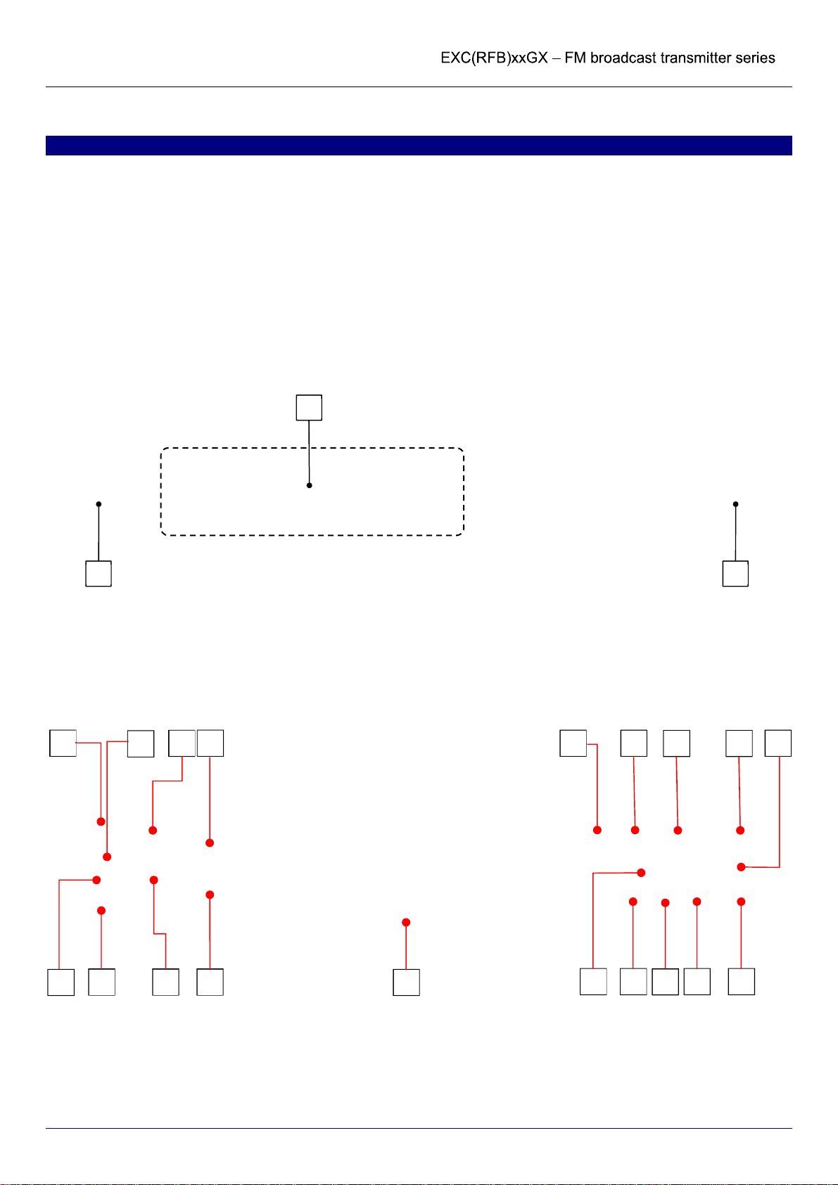
6.1.a EXC30GT Transmitter
Front
•Dimensions (LxHxD): 483 x 88 x 334 mm
•Weight: 7 kg
•Output connector: N
Rear
1
22
8
10 20
6 19
7 17 18
26 11 12 15
5 9
16
21
2225
24
User Manual Page 15 of 71
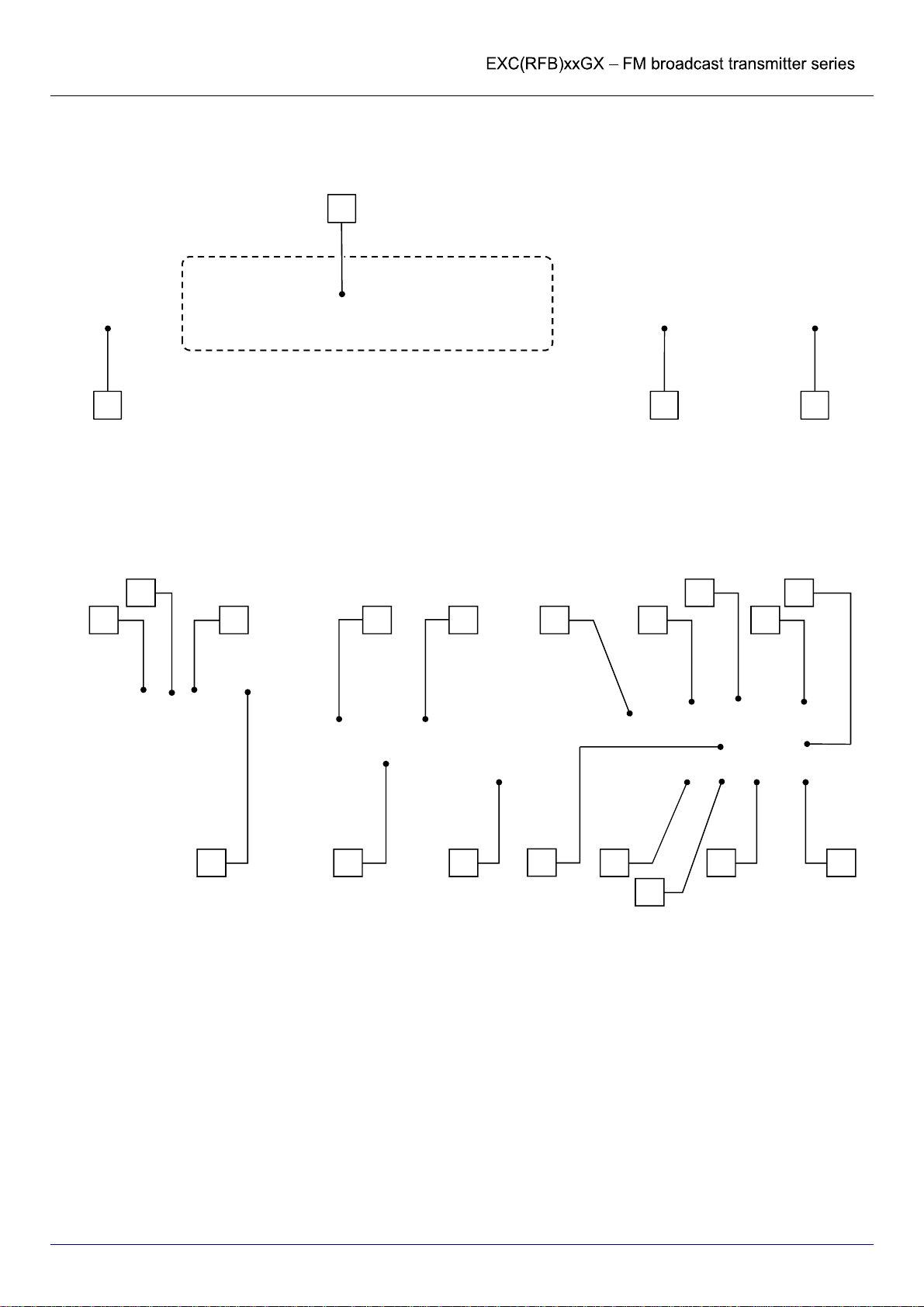
6.1.b EXC100-300GX Transmitters
Front
•Dimensions (LxHxD): 483 x 88 x 395 mm
•Weight: 8 kg
•Output connector: N
Rear
1
22 3
15
5
8 13
22
21
17
16
18
196
10
9
11
20257
24

User Manual Page 16 of 71
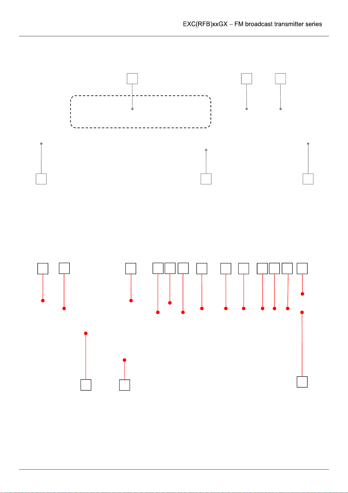
6.1.c EXC(RFB)500÷1600GX Transmitters and Amplifiers
Front
•Dimensions (LxHxD): 483 x 88 x 585 mm
•Weight: 12 kg
•Output connector: 7/16”
•Notes: these models internally differ for the type and/or number of output transistors/ RF power modules and/or the power
supply
Rear
1A
22
4
5 3
10
18
14 20/
23
22 21 15 16 17 19
713 8 249 27
User Manual Page 17 of 71
6.1.d EXC(RFB)2000GX Transmitter and Amplifier
Front
•Dimensions (LxHxD): 483 x 133 x 585 mm
•Weight: 21 kg
•Output connector: 7/16”
Rear
1A 4 5
3 22
8 25 15 16 17
20/
23
18
22
13
7
10
21
19
92427

User Manual Page 18 of 71
6.1.e EXC(RFB)3000-5000GX Transmitters and Amplifiers
Front
6.1.f
•Dimensions (LxHxD): 483 x 177 x 650 mm
•Weight: 30-33 kg
•Output connector: 7/8”
•Notes: these models internally differ for the type and/or number of the RF pallets / power supply modules. E.g.: EXC3000GX
(4/2), EXC3500GX (4/3), EXC5000GX (6/3). They all may be connected to single-phase or 3-phase mains network
Rear
2
1
2 3
4
10
147
21
5 22 19 25
18
20/
23 9 24
8
15 16 17

User Manual Page 19 of 71
6.2 List of commands and inputs
The commands and inputs that, according to your model, may be available on the device are listed below:
[1] Control panel 1 and 1A – allows the user to set device functions, and to view and set operating parameters. It is composed of
the following:
1
1A
•Liquid crystal display (LCD) – a graphics display that shows the operating parameters and functions selected via the multi-
function knob.
•ALARM indicator light (red) – this LED lights up in red if an alarm event occurs (e.g., output power or modulation too low).
•LIMITER indicator light (red) – this LED lights up in red to indicate that the maximum deviation limiter has activated due to an
audio signal that is too high.
•ON indicator light (yellow/green) – this LED lights up two ways:
•It lights up in yellow when the device is on stand-by
•It lights up in green when the device is in operation (powered up).
•LOCK indicator light (green) – this LED lights up in green to indicate that the internal frequency synthesizer is locked on the
set operating frequency.
•Multifunction knob (encoder) – allows the user to navigate the command menu in various ways:
•If turned – selects the various functions/operations for the device, or the parameter values to be set.
•If briefly pressed (like a button) when inside a menu – activates the option currently selected.
•When pressed longer (> 1 sec.) it act as ESCAPE button (see below)
•ESCAPE button – while navigating through a menu, pressing this button will return the user to the previous level. It may be
simulated by a long pressure on the multifunction knob. (see above)
•ON/STAND-BY button – starts the device or puts it on stand-by.
For further information regarding the use of navigation commands in the menu, see
8.1.
[2] Handles – allow the user to easily pick up the device to remove it from or insert it into a mobile rack.
[3] Front ventilation grill (only on some models) – allows the device to draw in cool air.
[4] Anterior RF MONITOR output (only on some models) – BNC-type connector for sourcing the low level RF signal; this function
is useful for connecting to external measurement units. The output level, depending on your model, ranges from 0 dBm to +15
dBm.
RF MONITOR output does not guarantee an output level that is perfectly constant as the frequency varies; as such, it cannot
be used for precision spectrum measurements.
[5] General power switch (POWER ON) – allows the user to turn the general system power on and off.
[6] Fuse holder (only on some models) – protective fuse holder for the power supply socket.

User Manual Page 20 of 71
[7] Power socket or cable – used to connect to a mains supply.
[8] Ground – used to ground the device, to ensure safe operation.
[9] Predisposition remote control antenna – input for an external GSM antenna (to be connected if the device is equipped with a
remote control option via the cellular phone network) (OPTIONAL).
[10] Antenna output socket/flange (RF OUTPUT) – this socket/flange is connected to an FM broadcasting antenna that can
tolerate the transmitter’s nominal power.
[11] Posterior RF MONITOR input (only on some models) – BNC-type connector for sourcing the low level RF signal. The signal
attenuation is typically ≈57 dB but may vary depending on models
[12] Heatsink (only on some models) – for dissipation of excess temperature during the transmitter power stages.
[13] Ventilation grill (only on some models) – for heat dissipation or, for models with forced air circulation, for expelling air brought
in through the front ventilation grill to cool the device.
[14] Cooling fan (only on some models) – expels air sucked in through the front ventilation grill used to cool the device.
[15] MODULATION MONITOR socket – BF modulation output socket to be used as a monitor, for synchronization of the RDS
encoder, or broadcast retransmission (BNC-type connector).
[16] AUX – auxiliary modulating channel input (RDS/SCA) at low frequency on a 20-100 KHz band (BNC-type unbalanced
connector with grounding shield) for connection to an RDS encoder. For details, see 0.
[17] MPX – externally created broadband stereo composite modulating signal input (BNC-type unbalanced connector with
grounding shield). For details, see 8.5.
[18] RS232 serial programming port – this female RS 232 Sub-D9 port with inverted cable allows the user to control the
transmitter via a computer or an external point-to-point control device. For details, see .
[19] REMOTE parallel control port – this 9-pin SUBD connector allows the user to remotely control the device or to perform other
functions via a suitable interface. For connections to this input, see chapter. For details, see 7.4.e.
On some models this general control port may be replaced by the dedicated RS232 control port of the RDS internal Generator
board if installed
[20] AES/EBU (female, optional) – input for AES/EBU digital LF modulation signal.
[21] LEFT – balanced input (female XLR) for modulation of the left audio channel. For details, see 8.5.
[22] RIGHT – balanced input (female XLR) for modulation of the right audio channel. This input can also accept a mono signal for
monophonic transmissions, as explained in Chap. 8.
[23] RF IN - female Nconnector, driver input from a low power exciter, provided only on RFBxxGX amplifiers
[24] RS485 serial port (only on some models or on request) – RS 485 serial port which allows the user to connect multiple
transmitters in series to an external controller, each of which is identified via a previously assigned logical address.
[25] Predisposition 10/100 T (only on some models) – input for LAN connection using 10/100 Base-TX standard Ethernet
(OPTIONAL).
[26] N+1 CONTROL (only on some models, on request) – 9 pins socket SUBD for remote control.
[27] RDS – (on request) 9 pole SUBD female connector for controlling an optional RDS internal Generator board. Whenever a
dedicated slot on the rear panel is absent, it may be placed instead of [19].
The central BNC pin of the MPX input [17] is physically in parallel to the + signal (pin 3) on the RIGHT XLR input for the right
channel [22]. As such, the connectors cannot both be used at the same time.
Other manuals for EXC GX Series
1
This manual suits for next models
22
Table of contents
Other sielco Transmitter manuals


