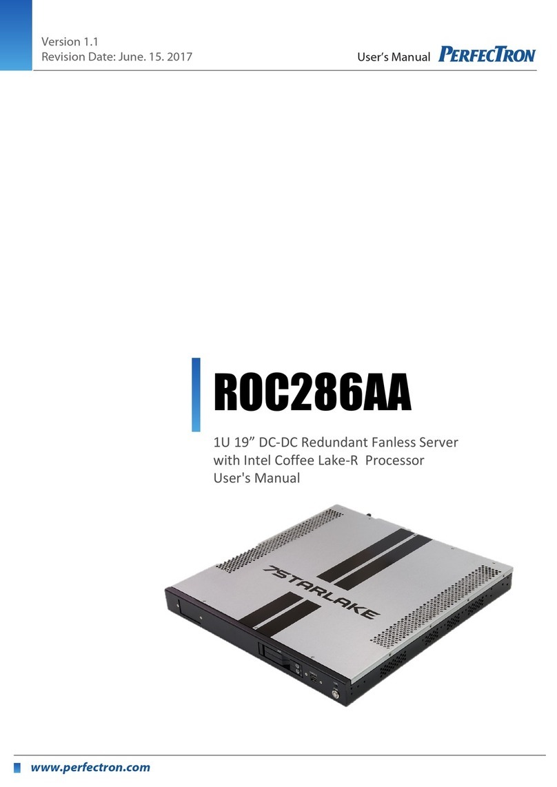
Siemens Nixdorf D853 User manual

PCPC
PCE-5S
The Intel Inside Logo is
a registered trademark
Technical Manual of Intel Corporation
Dieses Handbuch wurde auf Recycling-Papier gedruckt.
This manual has been printed on recycled paper.
Ce manuel est imprimé sur du papier recyclé.
Este manual ha sido impreso sobre papel reciclado.
Questo manuale è stato stampato su carta da riciclaggio.
Denna handbok är tryckt på recyclingpapper.
Dit handboek werd op recycling-papier gedrukt.
Published by
Siemens Nixdorf Informationssysteme AG
33094 Paderborn
81730 München
Order No.: A26361-K326-Z124-1-7619
Printed in the Federal Republic of Germany
AG 1194 11/94
A26361-K326-Z124-1-7619

Is there ...
... any technical problem or other ... anything you want to tell us
question you need clarified? about this manual?
Please send us your comments quoting
Please contact: the order number of the manual.
– one of our IT Service Shops
– your sales partner Siemens Nixdorf Informationssysteme AG
– your sales office User Documentation Department
BS2000 QM2, Otto-Hahn-Ring 6,
You will find the addresses of the 81730 München, Germany
IT Service Shops in the enclosed
warranty coupon booklet. Fax: (0 89) 6 36-4 04 43

Introduction
System unit
Interfaces, interrupts and
PCE-5S DMA assignment
Boards
Keyboard labeling
Technical Manual Index
November 1994 Edition
Your training needs . . .
The Siemens Nixdorf Training Centers offer you a wide range of
training courses in information technology and on IT products and
other subjects - onsite near to your workplace or offsite at one of our
training centers.
Contact us for information on consulting, course schedules and
selfstudy material.
Please write or fax:
Siemens Nixdorf Informationssysteme AG
Training Center, Beratungsservice
D-81730 München
Fax.: (089) 636-42945
Microsoft, MS and MS-DOS are registered trademarks and Windows is a trademark of
Microsoft Corporation.
Copyright Siemens Nixdorf Informationssysteme AG 1994.
All rights, including rights of translation, reproduction by printing, copying or similar methods,
even of parts, are reserved.
Offenders will be liable for damages.
All rights, including rights created by patent grant or registration of a utility model or design,
are reserved.
Delivery subject to availability; right of technical modifications reserved.

Contents
Introduction 1
Explanation of symbols 1
Safety 3
System unit 5
Opening the system unit 5
Removing top cover and side covers 6
Removing the front cover 9
Closing the system unit 10
Replacing the front cover 10
Replacing side covers and top cover 11
Installing and removing a board 15
Installing a board 15
Removing a board 17
Cabling of SCSI controller boards 19
Disk Array Controller on internal drives 19
Disk Array Controller on external drives 20
Standard SCSI controller on internal drives 21
Changing the processor board 22
Installing and removing memory modules 24
Removing the memory board 25
Installing memory modules 26
Removing memory modules 27
Installing the memory board 28
Installing and removing disk drives 29
Installing an accessible drive 29
Removing an accessible drive 34
Installing a non-accessible drive 37
Removing a non-accessible drive 40
Interrupts, DMAs, Interfaces 43
Interrupt and DMA assignment 43
Interrupt assignment 43
DMA assignment 43
Parallel interface (Centronics) 44
Keyboard interface 44
Serial interfaces 1 and 2 45
Mouse interface 45
SCSI interface 46
A26361-K326-Z124-1-7619
Contents
Boards 47
System board 47
Configuration options for the EISA slots 48
Terminating resistor for SCSI interface 1 48
DIP switches 48
Connection board 49
Connecting drives to SCSI controller 2 49
Keyboard labeling 51
Index 55
A26361-K326-Z124-1-7619

Introduction
This technical manual describes all the activities required to modify your PCE
hardware (e.g. installing boards or drives).
Modifications to the system unit very often require the system to be reconfigured
afterwards with the setup menu or the EISA configuration utility. Please read the
notes on this subject in the text. If certain system settings can be made using either
the setup menu or the EISA configuration utility, you should use the latter.
Some system extensions are supplied together with a floppy disk containing data
for the right board configuration. In such a case you must update your backup copy
of the Configuration Utility Disk (System Configuration Disk) before you install the
system expansion. Please read the section "Copy/update CFG. files" in the User
Guide of the EISA Configuration Utility.
Explanation of symbols
The meanings of the symbols and fonts used in this manual are as follows:
!Pay particular attention to texts marked with this symbol. They always
contain important information.
This symbol is followed by supplementary information, remarks and tips.
i
Texts which follow this symbol describe activities that must be performed in the
order shown.
This symbol means that you must enter a blank space at this point.
↵ This symbol means that you must press the Enter key.
Texts in this typeface are screen outputs from the PC.
Texts in this bold typeface are the entries you make via the keyboard.
Texts in italics indicate commands or menu items.
"Quotation marks" indicate highlighted text and names of chapters.
A26361-K326-Z124-1-7619 1

Safety
!Please note the information provided in the Operating Manual of the PCE.
Read these notes carefully and follow the instructions when you open your
PCE.
– The power switch does not disconnect the device from the line voltage. To do
this, you must pull out the power plug.
– Before opening the unit, first switch it off and then disconnect the power plug.
– No data transmission cable should be connected or disconnected during a
thunderstorm.
– Only qualified technicians may repair the device. Unauthorized opening or
incorrect repair may greatly endanger the user (electric shock, fire risk).
– Correct operation of the PC in accordance with IEC 950/EN60950 (cooling,
protection against fire, RFI suppression) is guaranteed only if the housing is
closed. Also put back the back cover for the slots.
– Install only system expansions that satisfy the requirements and rules governing
safety and electromagnetic compatibility and relating to telecommunications
terminal equipment. If you install other expansions, you may damage the
system or violate the safety regulations and regulations governing RFI
suppression. Information on which system expansions are suitable can be
obtained from the customer service or your sales office.
– The power supply unit (marked with a lightening flash symbol) should be
removed and replaced only by authorized specialists.
– If your PCE is equipped with a power outage fallback facility, the battery block
should be removed and replaced only by authorized specialists.
– Due to the danger of injury or electric shock, do not remove the rear part of the
casing.
– The warranty expires if the PCE is damaged during the installation or
replacement of system expansions.
A26361-K326-Z124-1-7619 3
Safety
!The real-time clock chip on the system board includes a lithium battery
which may be replaced only by authorized personnel. Incorrect handling
may lead to a risk of explosion.
The chip may be replaced only with an identical chip or with a type
recommended by the manufacturer.
The chip must be disposed of in accordance with local regulations
concerning special waste.
Modules with ESDs (electrostatic sensitive devices) may be identified by the
following label.
When you handle modules fitted with ESDs, you must observe the following points
under all circumstances:
– You must always discharge yourself (e.g. by touching a grounded object) before
working with modules containing ESDs.
– The equipment and tools you use must be free of static charges.
– Pull out the power plug before inserting or pulling out modules containing ESDs.
– Always hold modules with ESDs by their edges.
– Never touch pins or conductors on modules fitted with ESDs.
4A26361-K326-Z124-1-7619

System unit
Opening the system unit
Unlock the system unit.
Switch the PCE off.
Pull out the power plug.
If any cables attached to the system unit are obstructing you, pull out the
connectors on the system unit:
Unlock the cover at the rear of the system unit.
A26361-K326-Z124-1-7619 5
System unit Opening the system unit
12
Remove the cover at the rear of the system unit (1 + 2).
Pull out the connectors at the back of the system unit.
Removing top cover and side covers
Lift off the top cover.
6A26361-K326-Z124-1-7619

Opening the system unit System unit
1
2
Unscrew the screw 1.
If you are installing or removing a drive, also undo screw 2.
1
2
3
Pull off the first side cover upward at an angle (1 + 2 + 3).
If you are installing or removing a drive, also remove the second side cover by
pulling it upward at a slanting angle.
!Ensure that the two side covers are not confused.
A26361-K326-Z124-1-7619 7
System unit Opening the system unit
If you want to install or remove boards (e.g. expansion, memory or processor
boards), you must also remove the plastic side cover.
1
S1
2
If exist, pull the loudspeaker plug on the connection board (1).
Release the SCSI cable from the plastic cover (2).
1
2
Release the clamps (1), and remove the plastic cover (2).
8A26361-K326-Z124-1-7619

Opening the system unit System unit
Removing the front cover
You only need to remove the front cover if you are installing or removing a drive.
Press the four plastic retainers on the inside of the front cover upward at the
same time and tilt the cover forward as shown below.
1
2
2
Pull off the front cover upward at an slanting angle (1 + 2).
A26361-K326-Z124-1-7619 9
System unit Closing the system unit
Closing the system unit
To close the system unit, you must first replace the front cover if they have been
removed.
Replacing the front cover
1
2
1
Insert the lower plastic guides of the front cover into the openings in the system
unit (1).
Move the front cover up against the system unit until the four plastic retainers
latch (2).
10 A26361-K326-Z124-1-7619

Closing the system unit System unit
Replacing side covers and top cover
If you have installed or removed boards, you must first attach the plastic cover.
1
2
Insert the plastic cover as shown (1), and press in the left side until the clamps
latch (2).
1
2
S1
If exist, plug the loudspeaker cable into the connection board (1).
Attach the SCSI cable to plastic cover (2).
A26361-K326-Z124-1-7619 11
System unit Closing the system unit
!Ensure that the two side covers are not confused when they are installed.
3
2
1
Drop the side cover into the groove at a slanting angle (1).
Push the side cover up against the system unit (2), and lift the extensions of the
cover over the housing slots. Ensure that no cables are pinched.
Press the side cover downward (3).
1
2
Tighten screw (1).
12 A26361-K326-Z124-1-7619

Closing the system unit System unit
If you have also removed the second side cover, insert it likewise and fasten it
with screw (2).
Insert the top cover as shown and press it down into place.
Position the system unit at your workstation.
Plug in the cables of all units that were connected to the system unit.
2
1
Fasten the cover plate at the back of the system unit.
A26361-K326-Z124-1-7619 13
System unit Closing the system unit
Lock the cover plate at the back of the system unit.
Insert the power plug.
14 A26361-K326-Z124-1-7619

Installing and removing a board System unit
Installing and removing a board
Installing a board
Open the housing as described under "Opening the system unit".
Remove the screw and the rear slot cover plate.
!Do not dispose of the rear slot cover plate. If you remove the module again,
you must reattach the rear slot cover plate for cooling, protection against fire
and in compliance with the EMC regulations.
Take your board out of its packaging.
A26361-K326-Z124-1-7619 15
System unit Installing and removing a board
Push the board horizontally up against the system board at the rear. Ensure that
the metal bracket of the board is inserted between spring and slot.
Carefully press board into the slot.
Fasten the board in position with the screw you removed earlier.
Close the housing as described in "Closing the system unit".
Switch your PCE on.
Start the EISA configuration program to reconfigure your PCE. How to configure
the system is described in the User Guide of the EISA configuration program.
16 A26361-K326-Z124-1-7619

Installing and removing a board System unit
Removing a board
Open the housing as described under "Opening the system unit".
Remove the screw.
Pull the board out of the slot.
Place the board in its packaging.
!For cooling, protection against fire and in order to comply with EMC
regulations, you must refit the rear slot cover plate.
A26361-K326-Z124-1-7619 17
System unit Installing and removing a board
Replace the rear slot cover plate. Ensure that the rear slot cover plate is
inserted between spring and slot.
Fasten the rear slot cover plate with the screw you removed earlier.
Close the housing as described in "Closing the system unit".
Switch your PCE on.
Start the EISA configuration program to reconfigure your PCE. How to configure
the system is described in the User Guide of the EISA configuration program.
18 A26361-K326-Z124-1-7619

Disk Array Controller System unit
Cabling of SCSI controller boards
If the internal or external hard disk drives are not driven by the SCSI controllers
integrated on the system board but by a separate SCSI controller (standard SCSI
controller or Disk Array Controller), the following are changed: the cabling of the
hard disk drives, the allocation of the SCSI-ID and the position of the terminating
resistors. The following graphics show the three possible usages.
Disk Array Controller on internal drives
*) if available on DAC
Bay
6
5
4
1
2
3
SCSI-ID 0
resistor
installed
SCSI-ID 1
resistor
not installed
SCSI-ID 1
resistor
not installed
SCSI-ID 1
resistor
not installed
SCSI-ID 0
resistor
installed
SCSI-ID 0
resistor
installed
Channel 0 Channel 1
Channel 2
Disk Array Controller
Communicationchannel *
Channel 0
Overview: allocation of slot, SCSI-ID, SCSI channel and terminating resistor
A26361-K326-Z124-1-7619 19
System unit Disk Array Controller
Disk Array Controller on external drives
*) if available on DAC
Connector
panel
Channel 0 Channel 1
Channel 2
Disk Array Controller
Channel 0
Communicationchannel *
Overview: allocation of external connector and SCSI channel
20 A26361-K326-Z124-1-7619

Disk Array Controller System unit
Standard SCSI controller on internal drives
Bay
6
5
4
1
2
3
SCSI-ID 0
resistor
installed
SCSI-ID 1
resistor
not installed
SCSI-ID 3
resistor
not installed
SCSI-ID 4
resistor
not installed
SCSI-ID 5
resistor
not installed
SCSI-ID 2
resistor
not installed
SCSI connector
SCSI Controller
Overview: allocation of slot, SCSI-ID and terminating resistor
A26361-K326-Z124-1-7619 21
System unit Changing the processor board
Changing the processor board
Open the system unit as described under "Opening the system unit".
Pull the processor board out of the slot.
Place the processor board in its packaging.
Take the new processor board out of its packaging.
22 A26361-K326-Z124-1-7619

Changing the processor board System unit
Slide the processor board into the guides until it is up against the system board.
Carefully press the processor board into the slot on the system board until you
feel it engage.
Close the system unit as described in "Closing the system unit".
A26361-K326-Z124-1-7619 23
System unit Installing and removing memory modules
Installing and removing memory modules
In its basic configuration, the main memory has a capacity of 16 or 32 Mbytes and
can be expanded to 512 Mbytes by using 32-Mbyte-modules.
1
1 = memory bank
The memory board has 16 sockets for memory modules (SIMM - Single In-line
Memory Modules / PS/2 modules) which are divided into 8 memory banks with 2
sockets each. Memory modules have a capacity of either 8 or 32 Mbytes. A
memory bank must always be fully occupied and equipped with memory modules
of the same capacity. Thus, a memory capacity of 16 or 64 Mbytes is possible for
each memory bank, which permits a maximum memory expansion of 512 Mbytes.
The size of the memory modules may vary between memory banks. The 8 memory
banks can be equipped in any order. There may thus be unequipped memory
banks between equipped banks.
24 A26361-K326-Z124-1-7619

Installing and removing memory modules System unit
Removing the memory board
Open the housing as described in "Opening the system unit".
!Components may be damaged by static charges. Therefore, be sure to
follow the important guidelines at the beginning of this manual.
Pull the memory board from the slot.
A26361-K326-Z124-1-7619 25
System unit Installing and removing memory modules
Installing memory modules
When installing memory modules make sure that the memory modules already
installed do not hinder the installation of subsequent modules.
Insert the first memory module into its slot from the back at an angle of about
45˚.
Tilt the module carefully to the front until it snaps into place and is in a vertical
position in the socket.
Check that the memory module is securely in place in its socket.
The notches on the fastening clips must snap securely into place into the holes
on the memory module.
Repeat these steps for installing the second and each additional memory
module in its appropriate socket.
26 A26361-K326-Z124-1-7619

Installing and removing memory modules System unit
Removing memory modules
Memory modules must always be removed bank by bank, i.e. 2 modules at a time.
!Components may be damaged by static charges. Therefore, be sure to
follow the important guidelines at the beginning of this manual.
Press both fastening clips on the side of the socket outward using the tabs.
Tilt the memory module to the back and pull it out of its socket.
A26361-K326-Z124-1-7619 27
System unit Installing and removing memory modules
Repeat the steps for the second module of the memory bank/for the removal of
modules of other memory banks.
Installing the memory board
Slide the memory board into the guides until it is up against the system board.
Carefully press the memory board into the slot until you feel it engage.
Close the system unit as described in "Closing the system unit".
28 A26361-K326-Z124-1-7619

Installing and removing disk drives System unit
Installing and removing disk drives
In the system unit of the PCE, there is room for a total of ten drives.
All bays are of drawer design, thus simplifying installation and removal of the
drives. The top four bays (1 - 4) are intended for four accessible drives of half
height (slimline), either in 3 1/2" or 5 1/4" format. Instead of two half-height drives,
one full-height drive can be installed. The lower six bays (5 - 10) are intended for
non-accessible 3 1/2" SCSI drives.
When installing a SCSI drive (e.g. hard disk, streamer or CD ROM drive), first read
the documentation which comes with your SCSI drive.
An address (identification number or ID) must be set for each SCSI drive.
As standard, the terminating resistor is plugged in at the hard disk installed in the
lowest bay (ID=0).
!The address of the installed hard disk (ID=0) must not be modified since the
system BIOS requires this address for booting the system.
Installing an accessible drive
!SCSI drives in bays 1 - 4 may not have terminating resistors.
Open the system unit as described under "Opening the system unit".
Select an installation position appropriate for the drive (half-height, full-height).
A26361-K326-Z124-1-7619 29
System unit Installing and removing disk drives
Unscrew the mounting screws on the drawer containing the bay in question and
remove the associated metal plates.
Pull the drawer out of the system unit.
For each drive in bays 1 to 4, you require an adapter for connection to the system.
Floppy disk drives and SCSI drives require different adapters. A suitable adapter is
supplied with each drive.
30 A26361-K326-Z124-1-7619

Installing and removing disk drives System unit
Screw the adapter to the rear of the drawer as shown. Ensure that the adapter
is screwed in the right way round. The cables must always be on top, the
connector for the connection board at the bottom.
The drive is either installed as a "visible" or "concealed" drive. Installation depends
on whether the drive should be accessible from the outside (e.g. floppy disk drive,
CD-ROM) or not (hard disk).
Place the drive in the drawer.
Screw down the drive in accordance with the type of installation.
A26361-K326-Z124-1-7619 31
System unit Installing and removing disk drives
Connect the data cable to the drive. Ensure that the connector is plugged in the
right way round (coding).
Plug the power supply connector into the drive.
Slide the drawer into the system unit.
Attach the drawer and, if you have installed a drive to be concealed (non-
accessible), also screw down the metal plates previously removed.
32 A26361-K326-Z124-1-7619
This manual suits for next models
1
Table of contents
Other Siemens Nixdorf Computer Hardware manuals

