Siemens Nixdorf D842 User manual

PCPC
System board D842
ISA / PCI
Technical Manual
Dieses Handbuch wurde auf Recycling-Papier gedruckt.
This manual has been printed on recycled paper.
Ce manuel est imprimé sur du papier recyclé.
Este manual ha sido impreso sobre papel reciclado.
Questo manuale è stato stampato su carta da riciclaggio.
Denna handbok är tryckt på recyclingpapper.
Dit handboek werd op recycling-papier gedrukt.
Herausgegeben von/Published by
Siemens Nixdorf Informationssysteme AG
D-33094 Paderborn
D-81730 München
Bestell-Nr./Order No.: A26361-D842-Z120-1-7619
Printed in the Federal Republic of Germany
AG 0496 04/96
A26361-D842-Z120-1-7619

Is there ...
... any technical problem or other ... anything you want to tell us
question you need clarified? about this manual?
Please send us your comments quoting
Please contact: the order number of the manual.
– one of our IT Service Shops
– your sales partner Siemens Nixdorf Informationssysteme AG
– your sales office User Documentation Department
BS2000 QM2, Otto-Hahn-Ring 6,
You will find the addresses of the 81730 München, Germany
IT Service Shops in the enclosed
warranty booklet. Fax: ++49 89 / 6 36-4 04 43

Introduction
Important notes
System board D842 Settings in BIOS Setup
ISA / PCI Switch block and
jumper settings
Add-on modules
Interface assignment and
Technical Manual IRQs
Error messages
Index
April 1996 edition
Your training needs . . .
The Siemens Nixdorf Training Centers offer you a wide range of training courses in
information technology and on IT products and other subjects - onsite near to your
workplace or offsite at one of our training centers.
Contact us for information on consulting, course schedules and
selfstudy material.
Please write or fax:
Siemens Nixdorf Informationssysteme AG
Training Center, Beratungsservice
D-81730 München
Fax.: ++49 89 636-42945
Adaptec is a registered trademark of Adaptec Inc.
Intel and Pentium are registered trademarks and OverDrive is a trademark of Intel
Corporation, USA.
Microsoft, MS, MS-DOS, Windows and Windows 95 are registered trademarks of Microsoft
Corporation.
PS/2 and OS/2 Warp are registered trademarks of International Business Machines, Inc.
SCO and SCO Unix are registered trademarks of Santa Cruz Operation.
All other trademarks referenced are the trademarks or registered trademarks of their
respective owners, whose protected rights are acknowledged.
Copyright Siemens Nixdorf Informationssysteme AG 1995
All rights, including rights of translation, reproduction by printing, copying or similar methods,
even of parts are reserved.
Offenders will be liable for damages.
All rights, including rights created by patent grant or registration of a utility model or design,
are reserved.
Delivery subject to availability; right of technical modifications reserved.

Contents
Introduction 1
Notational conventions 1
Features 2
Possible screen resolution 3
Important notes 5
Notes on software 6
Settings in BIOS Setup 7
System settings - Main menu 7
Time and Date - System Time / System Date 8
Floppy disk drive - Diskette A / Diskette B 8
Hard disk drives - Hard Disk 1 to Hard Disk 4 9
System Startup - Boot Options 12
Type of monitor - Video Display 13
Base Memory 13
Extended Memory 13
Making advanced system settings - Advanced menu 14
Cache - Cache Memory 15
ROM areas in the RAM - Shadow Memory 17
Peripheral Configuration - Interfaces and controllers 18
PCI Configuration 21
Advanced System Configuration 23
Plug&Play functionality - Plug & Play O/S 24
Reset Configuration Data 25
Hard disk access - Large Disk Access Mode 25
Setting up the security features - Menu Security 26
Setup Password / System Password 26
Set Setup Password 27
Set Setup Lock 27
Set System Password 27
System Password Mode 27
System Load 28
Setup Prompt 28
Virus Warning 28
Write protection for floppy disk drive - Diskette Write 29
Write protection for System BIOS - Flash Write 29
Soft Power Off 29
Remote Power On 29
A26361-D842-Z120-6-7619
Contents
Setting energy saving functions - Power menu 30
Enabling the APM Interface - APM 30
Extent of energy saving functions - Power Management Mode 31
Standby mode - Standby Timeout 32
Hard disk energy saving functions - Hard Disk Timeout 32
Processor clock - Standby CPU Speed 32
Wakeup Event - Defininig system activities 33
Exiting BIOS Setup - Exit menu 33
Save Changes & Exit 33
Discard Changes & Exit 33
Get Default Values 34
Load Previous Values 34
Save Changes 34
Second-level cache 34
Switch block and jumper settings 35
BIOS recovery - Switch 1 35
BIOS update - Switch 3 36
Write protection for floppy disk drive - Switch 4 36
Keyboard and pointing device - Jumper 36
Add-on modules 37
Upgrading main memory 37
Installing memory modules 38
Removing a memory module 38
Replacing the processor 39
Upgrading the video memory 41
Replacing the lithium battery 42
Interface pinouts and interrupts 43
Connector for 5 V power supply 43
Connector for 3.3 V power supply 43
Connector for soft-off power supply 44
Connector for soft-off power switch 44
Connector for external loudspeaker 44
Connector for remote power-on 44
Connector for LED indicators 45
Connector for SCSI HD LED indicators 45
Connector for external monitor controller
(VESA VGA pass-through) 46
Connector for Imageport 47
Connector for monitor 48
Parallel interface 49
A26361-D842-Z120-6-7619

Contents
Pinout in SPP mode 49
Pinout in EPP mode 50
Pinout in ECP mode 50
Serial interface 51
PS/2 mouse port 52
PS/2 keyboard port 52
Interrupt Request Levels and DMA channels 53
Error messages 55
Messages d'erreur 57
Mensajes de error 59
Messagi di errore 61
Felmeddelanden 63
Foutmeldingen 65
Index 67
A26361-D842-Z120-6-7619

Introduction
This description applies for the system board D842 with PCI bus (Peripheral
Component Interconnect).
Notational conventions
The meanings of the symbols and fonts used in this manual are as follows:
!This indicates instructions which it is essential to observe. Failure to do so
may endanger your health, the operational integrity and electrical safety of
your PC, or the security of your data.
This symbol is followed by supplementary information, remarks and tips.
i
Texts which follow this symbol describe activities that must be performed in the
order shown.
This symbol means that you must enter a blank space at this point.
↵ This symbol means that you must press the Enter key.
Texts in this typeface are screen outputs from the PC.
Texts in this bold typeface are the entries you make via the keyboard.
Texts in italics indicate commands or menu items.
"Quotation marks" indicate highlighted text and names of chapters.
A26361-D842-Z120-6-7619 1
Introduction
Features
– 64-bit microprocessor Pentium with 16 Kbyte internal cache (first-level cache;
8 Kbyte data cache, 8 Kbyte address cache) or
OverDrive processor for Pentium
– Math coprocessor: integrated in processor
– Memory configuration on system board: 8 Mbyte to 128 Mbyte
– Second-level cache on the system board: 256 Kbyte
– PCI bus
– Disk controller connected to PCI bus for up to four IDE drives
(e.g. fast IDE hard disk drives, IDE CD ROM drive)
– Monitor controller connected to PCI bus; graphics processor
TSENG ET4000/W32P with Windows accelerator and 1 Mbyte or 2 Mbyte
DRAM video memory
– Real-time clock/calendar with integrated battery backup
– 128 Kbyte Flash BIOS
– Floppy disk controller (up to 2.88 Mbyte format)
– Bus interface for platter
– Connector for external loudspeaker
– Connector for external monitor controller (VESA VGA pass-through)
– Imageport connector
– Parallel interface (ECP- and EPP-compatible)
– Two serial interfaces
– PS/2 mouse interface
– PS/2 keyboard interface
– Monitor interface
– Location bank for voltage converter
2A26361-D842-Z120-6-7619

Introduction
12345678911
12
13 14
15 16
17
18
19
20
21
22
23
25
27 24
10
26
28
1 = Monitor interface 16 = Location bank 0 for main memory
2 = Parallel interface 17 = Connector for soft-off power switch
3 = Serial interface 2 18 = Connector for LED indicators
4 = Serial interface 1 19 = Connector for external
5 = PS/2 mouse port loudspeaker
6 = PS/2 keyboard port 20 = Socket for processor fan
7 = Bus interface 21 = Processor with heat sink
8 = Connector for power supply 5 V 22 = Voltage converter
9 = Connector for remote on 23 = Connector for LED indicator of
10 = Connector for power supply 3,3 V SCSI hard disk drive
11 = Connector for soft-off power supply 24 = Imageport connector
12 = Connector 1 for IDE drives 1 and 2 25 = Sockets for video memory
(e.g. hard disk drive) 26 = Lithium battery
13 = Connector 2 for IDE drives 3 and 4 27 = Connector for external monitor
14 = Connector for floppy disk drive controller
15 = Location bank 1 for main memory (VESA VGA pass-through)
28 = Switch block
Possible screen resolution
The screen resolutions in the following table refer to the monitor controller on the
system board.
If you are using an external monitor controller, you will find details of supported
screen resolutions in the Operating Manual or Technical Manual supplied with the
controller.
A26361-D842-Z120-6-7619 3
Introduction
You can use the REFRATE program (under Windows 95), the WDSETUP program
(under MS-Windows) or the SET-VGA program (under MS-DOS) to set the screen
resolution. Detailed information is provided in the corresponding help.
!You may set only those resolutions and refresh rates specified in the
"Technical data" section of the monitor description. Otherwise you may
damage your monitor. If you are in any doubt, contact your sales office or
customer service.
Screen Refresh Horizontal- Max. number
resolution rate (Hz) frequency (kHz) of colors
640x350 70 31,3 16
640x350 84 38 16
640x480 60 31,3 16777216
640x480 75 38 16777216
640x480 90 48 65536
720x400 70 31,5 16
720x400 84 38 16
800x600 56 35 16777216 *)
800x600 56 35 65536
800x600 60 38 16777216 *)
800x600 60 38 65536
800x600 75 47 65536
800x600 90 60 256
1024x768 87 interlaced 36 65536 *)
1024x768 87 interlaced 36 256
1024x768 60 49 65536 *)
1024x768 60 49 256
1024x768 70 57 256
1024x768 75 60 256
1280x1024 87 interlaced 49 256 *)
1280x1024 87 interlaced 49 16
1280x1024 60 64 256 *)
1280x1024 75 80 256 *)
*) Only with 2 Mbyte of video memory
4A26361-D842-Z120-6-7619
Important notes
!Be sure to read this page carefully and note the information before you
open the PC.
Please note the information provided in the chapter "Safety" in the
Operating Manual of the PC.
Incorrect replacement of the lithium battery may lead to a risk of explosion.
It is therefore essential to observe the instructions in the section "Add-on
modules - Replacing the lithium battery".
The lithium battery must be replaced with an identical battery or a battery
type recommended by the manufacturer (CR2032).
Do not throw lithium batteries into the trashcan. Your vendor or dealer or
their authorized representatives will take used batteries back free of charge
so that they can be recycled or disposed of in the proper manner.
ADVARSEL
!Lithiumbatteri - Eksplosionsfare ved fejlagtig håndtering. Udskiftning må kun
ske med batteri af samme fabrikat og type. Lever det brugte batteri tilbage
til leverandøren.
ADVARSEL
!Eksplosjonsfare ved feilaktig skifte av batteri. Benytt samme batteritype eller
en tilsvarende type anbefalt av apparatfabrikanten. Brukte batterier
kasseres i henhold til fabrikantens instruksjoner.
VARNING
!Eksplosionsfara vid felaktigt batteribyte. Använd samma batterityp eller en
ekvivalent typ som rekommenderas av apparattillverkarenfabrikanten.
Kassera använt batteri enligt fabrikantens instruktion.
VAROITUS
!Paristo voi räjähtää, jos se on virheellisesti asennettu. Vaihda paristo
ainoastaan laitevalmistajan suosittelemaan tyyppiin. Hävitä käytetty paristo
valmistajan ohjeiden mukaisesti.
A26361-D842-Z120-6-7619 5
Important Notes
Modules with electrostatic sensitive devices (ESD) may be identified by labels.
When you handle modules fitted with ESDs, you must observe the following points
under all circumstances:
– When you handle modules fitted with ESDs, you must always discharge yourself
(e.g. by touching a grounded object) before working.
– The equipment and tools you use must be free of static charges.
– Pull out the power plug before inserting or pulling out modules containing ESDs.
– Always hold modules with ESDs by their edges.
– Never touch pins or conductors on modules fitted with ESDs.
Notes on software
Program with time loops
Problems can occur with programs in which time loops have been implemented
through software loops. This applies in particular to older programs which were
written for 8 MHz processors.
SCO UNIX on devices with Pentium or OverDrive processor
Please note the following:
If you use one of the processors mentioned above, the Adaptec-SCSI controller
cannot be addressed under SCO-UNIX 3.2.4 and ODT 2.0.
To solve this problem, you can order from SCO a set of SLS (Support Level
Supplement) floppies (consisting of 3 floppy disks) under the number uod361,
free of charge, or contact one of our IT Service Shops.
The problem no longer exists in the new releases of SCO-UNIX 3.2.4.2 and
ODT 2.1.
There will be no support for older versions (SCO-UNIX versions lower than 3.2.4
and ODT versions lower than 2.0).
6A26361-D842-Z120-6-7619

Settings in BIOS Setup
The BIOS Setup menu allows you to set your hardware configuration and system
functions. In addition, the BIOS Setup displays technical information on the PC's
configuration.
Pressing the function key F1 provides help information on each entry field.
When it is supplied, the PC is set to factory default settings which you can alter in
the BIOS Setup menus. Any changes you make take effect as soon as you save the
settings and quit the BIOS Setup.
The Operating Manual describes how to call the setup menu and change menu
entries.
You can select the following settings in the BIOS Setup:
Main - system functions
Advanced - advanced system configuration
Security - security features
Power - power-management features
Exit - save and quit
The various menus are described below with all setting options. Since the
isetting options depend on your PC's hardware configuration, some of them
may not be offered in the BIOS setup.
System settings - Main menu
In the Main menu you can set up the following:
– Time (in the field marked System Time)
– Date (in the field marked System Date)
– Floppy disk drive (in the field marked Diskette A or Diskette B)
– Hard disk drive (in the submenus of Hard Disk)
– System boot (in the submenus of Boot Options)
– Display device (in the field marked Video Display)
A26361-D842-Z120-6-7619 7
Settings in BIOS Setup Main
Phoenix BIOS Setup Copyright 1985-94 Phoenix Technologies Ltd.
Main Advanced Security Power Exit
Item Specific Help
System Time: [07:42:19] –––––––––––––––––––––––
System Date: [02/28/1995]
Diskette A: [1.4M]
Diskette B: [None]
Hard Disk 1: 540 Mbyte
Hard Disk 2: None
Hard Disk 3: None
Hard Disk 4: None
Boot Options
Video Display: [EGA/VGA]
Base Memory: 640K
Extended Memory: 15M
F1 Help ↑↓ Select Item -/+ Change Values F9 Setup Defaults
ESC Exit ←→ Select Menu Enter Execute Command F7 Previous Values
Example for Main menu
Time and Date - System Time / System Date
The System Time field and the System Date field show the time and date respectively
according to the PC. The time is shown in the format hours:minutes:seconds and the
date is shown in the format month/day/year. You can move the cursor within the
Time and Date fields (e.g. from hour to minute) using the tabulator key.
!If the settings in the System Time and System Date fields are frequently wrong
when you power up the computer, the lithium battery is dead. Change the
battery as described in "Add-on modules - Replacing the lithium battery").
Floppy disk drive - Diskette A / Diskette B
These two fields are used to specify the type of floppy disk drive installed.
360K, 720K, 1.2M, 1.4M, 2.8M
The entry depends on the floppy disk drive installed.
(Default entry Diskette A:1.4M)
None A floppy disk drive is not installed.
(Default entry Diskette B:None)
8A26361-D842-Z120-6-7619
Main Settings in BIOS Setup
Hard disk drives - Hard Disk 1 to Hard Disk 4
call the submenu to make corresponding settings of the IDE hard disk drive.
You should change the default settings only if you are connecting an
iadditional IDE drive to one of the two IDE connectors.
The maximum transfer rate of two IDE drives connected to the same
connector is determined by the slower of the two. Fast hard disks should
therefore be connected to the first IDE connector and identified as Hard
Disk 1 or Hard Disk 2; slower hard disks or other IDE drives (e.g.
CD ROM drives) should be connected to the second IDE connector and
identified as Hard Disk 3 or Hard Disk 4.
The following description of the setting options for Hard Disk 1 also applies to
Hard Disk 2, Hard Disk 3 and Hard Disk 4. The default settings depend on the
installed drive.
Phoenix BIOS Setup Copyright 1985-94 Phoenix Technologies Ltd.
Main
Hard Disk 1: 540 Mbyte Item Specific Help
Autotype Hard Disk: [Press Enter]
Type: [User] 540 Mbyte
Cylinders: [ 1046]
Heads: [ 16]
Sectors/Track: [ 63]
Write Precomp: [None]
Transfer Mode: [Standard]
LBA Translation: [Disabled]
PIO Mode: [Standard]
32 Bit I/O: [Enabled]
F1 Help ↑↓ Select Item -/+ Change Values F9 Setup Defaults
ESC Exit ←→ Select Menu Enter Execute Command F7 Previous Values
Example for the submenu Hard Disk 1
A26361-D842-Z120-6-7619 9
Settings in BIOS Setup Main
Only if you have installed a new IDE hard disk drive, you should mark the Autotype
Hard Disk field and press Enter. This has the effect of setting the optimum values
for the IDE hard disk drive. You can change these values if you set the Type field to
User.
Type - Hard Disk Type
This field is used to specify the type of hard disk drive installed.
None You cannot change the hard disk parameters (Cylinders, Heads,
Sector/Track and Write Precomp). Either an IDE drive has not been
installed, or the values have been set with Autotype Hard Disk.
1 to 39 The hard disk parameters (Cylinders, Heads, etc.) are preset.
Auto If the hard disk supports this mode, the setup menu reads the hard
disk parameters from the disk itself and sets them automatically.
You do not need to select the parameters yourself.
User You can enter the hard disk parameters (Cylinders, Heads etc.)
yourself.
If you have set the hard disk parameters with Autotype Hard Disk,
you can only reduce the values.
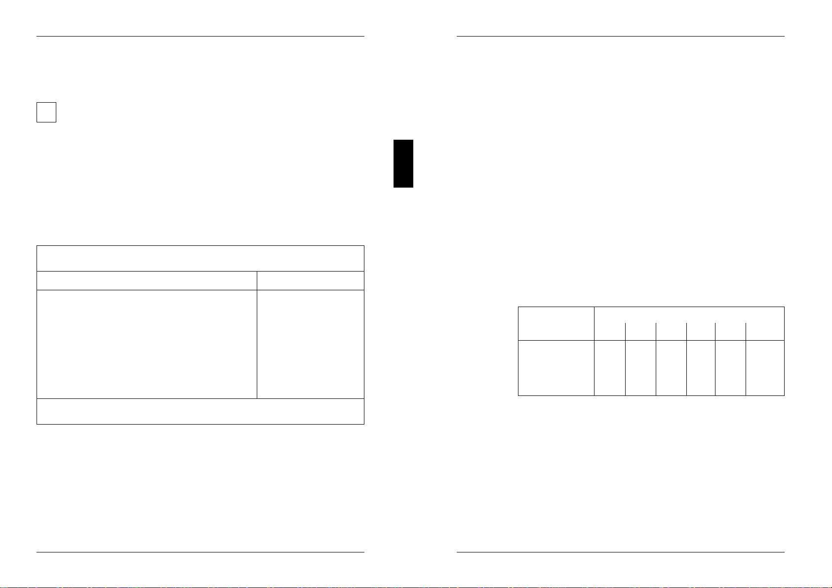
Examples of user-defined entries (IDE drives):
hard disk hard disk capacity in Mbyte
parameter 210 270 340 540 850 1024
Cylinders 683 915 904 1046 1654 2097
Heads 16 12 16 16 16 16
Sectors 38 48 46 63 63 63
Write Precomp None None None None None None
Cylinders, Heads, Sectors/Track, Write Precomp - hard disk parameter
These hard disk parameters are set in accordance with the IDE hard disk drive. If
you want to change the hard disk parameters manually, set the Type field to User.
10 A26361-D842-Z120-6-7619

Main Settings in BIOS Setup
Transfer Mode
This field specifies the transfer mode for the IDE hard disk drive.
Standard One block is transferred for each interrupt (default entry).
2 Sectors, 4 Sectors, 6 Sectors, 8 Sectors, 16 Sectors
The set number of blocks (sectors) is transferred for each interrupt.
LBA Translation - Addressing
This field enables and disables the LBA (Logical Block Addressing) mode. LBA
mode allows you to install and use hard disks with a capacity of more than 528
Mbytes. If a hard disk supports LBA mode, you can use the full capacity of the IDE
hard disk.
The default entry depends on the installed IDE hard disk drive. Change the default
entries only if you are installing another hard disk drive.
!You may only use IDE drives in the LBA mode selected when they were set
up. In other words, if you set up a hard disk with LBA mode DISABLED, you
may only operate the hard disk with LBA mode DISABLED.
Enabled If the hard disk supports LBA and it has a capacity of more than
528 Mbytes, the BIOS translates the hard disk parameters, allowing
the disk's full capacity to be used.
If the hard disk does not support LBA, its parameters are not
translated.
Disabled The BIOS uses the hard disk parameters and supports a maximum
capacity of 528 Mbytes.
PIO Mode - Transfer rate
The PIO (Programmed Input Output) Mode defines the transfer rate of the IDE hard
disk drive.
Standard 0,8 Mbyte/s to 2 Mbyte/s. (default entry)
Fast PIO 1 2 Mbyte/s to 4 Mbyte/s.
Fast PIO 2 4 Mbyte/s to 5 Mbyte/s.
Fast PIO 3 5 Mbyte/s to 10 Mbyte/s.
A26361-D842-Z120-6-7619 11
Settings in BIOS Setup Main
32 Bit I/O - Bus width for data transfer
specifies the width of data transmission between the processor and the IDE
controller.
Enabled The data transfer is 32 bits in width at the PCI bus. This enhances
performance (default entry).
Disabled The data transfer is 16 bits in width.
System Startup - Boot Options
calls the submenu in which you can select the settings for system startup of the
PC.
Phoenix BIOS Setup Copyright 1985-94 Phoenix Technologies Ltd.
Main
Boot Options Item Specific Help
POST Error Halt: [Halt On All Errors]
Quick Boot: [Disabled]
F1 Help ↑↓ Select Item -/+ Change Values F9 Setup Defaults
ESC Exit ←→ Select Menu Enter Execute Command F7 Previous Values
Example for submenu Boot Options
12 A26361-D842-Z120-6-7619

Main Settings in BIOS Setup
POST Error Halt - Aborting system startup
defines whether the system startup is to be aborted and the system halted when an
error is detected.
Halt On All Errors
If the self-test detects an error, system startup is aborted after the
self-test, and the system is halted (default entry).
No Halt On Any Errors
The system startup is not aborted. The error is ignored as far as
possible.
Quick Boot
can reduce the extent of the self-test and thus accelerate the system startup.
Enabled When the PC is switched on, the quick self-test is carried out, in
which the floppy disk drives are not checked.
Disabled When the PC is switched on, the complete PC configuration is
tested (default entry).
Type of monitor - Video Display
This field is used to specify the type of monitor connected.
EGA/VGA, Color 80, Monochrome
Default entry: EGA/VGA
Base Memory
This field indicates the size of the available base memory below 1 Mbyte.
Extended Memory
This field indicates the size of the memory above 1 Mbyte.
A26361-D842-Z120-6-7619 13
Settings in BIOS Setup Advanced
Making advanced system settings -
Advanced menu
!Change the default settings only for special applications. Incorrect settings
can cause malfunctions.
You can make the following system settings in the Advanced menu:
– Internal cache and second-level cache (in the Cache Memory submenu)
– Copy BIOS sections to the RAM (in the Shadow Memory submenu)
– Interfaces and controllers (in the Peripheral Configuration submenu)
– PCI functionality (in the PCI Configuration submenu)
– Data access to hard disk (in the Advanced System Configuration submenu)
– Plug&Play functionality (in the Plug and Play O/S field)
– Configuration data (in the Reset Configuration Data field)
– Hard disk access (in the Large Disk Access Mode field)
Phoenix BIOS Setup Copyright 1985-94 Phoenix Technologies Ltd.
Main Advanced Security Power Exit
Item Specific Help
Warning! –––––––––––––––––––––––
Setting items on this menu to incorrect values
may cause your system to malfunction.
Cache Memory
Shadow Memory
Peripheral Configuration
PCI Configuration
Advanced System Configuration
Plug & Play O/S: [No]
Reset Configuration Data: [No]
Large Disk Access Mode: [DOS]
F1 Help ↑↓ Select Item -/+ Change Values F9 Setup Defaults
ESC Exit ←→ Select Menu Enter Execute Command F7 Previous Values
Example for the Advanced menu
14 A26361-D842-Z120-6-7619

Advanced Settings in BIOS Setup
Cache - Cache Memory
calls the submenu in which you can make the settings for the internal cache (in the
processor) and the second-level cache (on the system board).
Phoenix BIOS Setup Copyright 1985-94 Phoenix Technologies Ltd.
Advanced
Cache Memory Item Specific Help
Cache: [Intern And Extern]
Cache Mode: Write Back
Cache System BIOS Area: [Enabled]
Cache Video BIOS Area: [Enabled]
Cache Memory Regions
C800 - CBFF: [Disabled]
CD00 - CFFF: [Disabled]
D000 - D3FF: [Disabled]
D400 - D7FF: [Disabled]
D800 - DBFF: [Disabled]
DC00 - DFFF: [Disabled]
F1 Help ↑↓ Select Item -/+ Change Values F9 Setup Defaults
ESC Exit ←→ Select Menu Enter Execute Command F7 Previous Values
Example for submenu Cache Memory
Cache - cache utilization
This field switches the cache on and off. The cache is a buffer to which parts of the
main memory and BIOS can be temporarily copied. The PC's performance is
higher when the cache is switched on.
You must disable the cache if:
– the access time is too short for older applications
– you are installing OS/2 Warp
Intern Only Only the internal cache is used.
Intern And Extern
Internal (first-level cache) and external cache (second-level cache)
are enabled. If there is no external Cache, only the internal cache is
used (Default entry).
Disabled Internal (first-level cache) and external cache (second-level cache)
are disabled. All cache-related settings are then without effect.
A26361-D842-Z120-6-7619 15
Settings in BIOS Setup Advanced
Cache Mode
Condition: The Cache field must be set to Intern Only or Intern And Extern.
Cache Mode sets the mode in which the CPU uses the cache.
In write-back mode the CPU writes information to the cache and the information is
only written to main memory if necessary. Memory and cache contents are not
identical. In write-back mode the performance is higher than in write-through mode.
In write-through mode the processor writes the information to the cache and to
main memory. The contents of memory and cache are identical.
Write Back The cache works in write-back mode (fixed).
Cache System BIOS Area / Cache Video BIOS Area
Condition: The Cache field must be set to Intern only or Intern and Extern.
Cache System BIOS Area and Cache Video BIOS Area lets you specify the BIOS that
should be mapped to the cache. Mapping the BIOS to the cache increases system
performance.
Enabled The specified BIOS is mapped to the cache (default entry).
Disabled The specified BIOS is not mapped to the cache.
Cache Memory Regions
Condition: The Cache field must be set to Intern only or Intern and Extern.
Cache Memory Regions lets you specify the BIOS ROM areas that should be
mapped to the cache. Mapping the BIOS ROM areas to the cache increases
system performance.
Enabled The relevant ROM area is mapped to the cache.
Disabled The relevant ROM area is not mapped to the cache (default entry).
16 A26361-D842-Z120-6-7619

Advanced Settings in BIOS Setup
ROM areas in the RAM - Shadow Memory
calls the submenu in which you can specify which parts of the ROM (Read Only
Memory) are to be copied to the faster RAM (Random Access Memory) at system
startup.
Phoenix BIOS Setup Copyright 1985-94 Phoenix Technologies Ltd.
Advanced
Shadow Memory Item Specific Help
System Shadow: Enabled
Video Shadow: [Enabled]
Shadow Memory Regions
C800 - CBFF: [Disabled]
CC00 - CFFF: [Disabled]
D000 - D3FF: [Disabled]
D400 - D7FF: [Disabled]
D800 - DBFF: [Disabled]
DC00 - DFFF: [Disabled]
F1 Help ↑↓ Select Item -/+ Change Values F9 Setup Defaults
ESC Exit ←→ Select Menu Enter Execute Command F7 Previous Values
Example for submenu Shadow Memory
System Shadow
This field is always Enabled, because the System BIOS is automatically copied to
the faster RAM.
Video Shadow
This field allows you to copy the video BIOS to fast RAM. Copying the video BIOS
to fast RAM increases system performance.
Enabled The video BIOS is copied to fast RAM (default entry).
Disabled The video BIOS is not copied to fast RAM. This setting is not
effective unless an external monitor controller is used.
A26361-D842-Z120-6-7619 17
Settings in BIOS Setup Advanced
Shadow Memory Regions - ROM areas
Shadow Memory Regions allows you to copy ROM areas to fast RAM. Copying ROM
areas to fast RAM increases system performance.
Enabled The ROM area is copied to fast RAM.
Disabled The ROM area is not copied to fast RAM (default entry).
Peripheral Configuration - Interfaces and controllers
calls the submenu in which you can set the interfaces and controllers.
Phoenix BIOS Setup Copyright 1985-94 Phoenix Technologies Ltd.
Advanced
Peripheral Configuration Item Specific Help
Serial 1: [Auto]
Serial 2: [Auto]
Parallel: [Auto]
Parallel Mode: [Printer]
Diskette Controller: [Enabled]
Hard Disk Controller: [Primary And Secondary]
Mouse Controller: [Enabled]
F1 Help ↑↓ Select Item -/+ Change Values F9 Setup Defaults
ESC Exit ←→ Select Menu Enter Execute Command F7 Previous Values
Example for submenu Peripheral Configuration
Serial 1 / Serial 2 - Serial interfaces
This field selects the address and the interrupt used to access the relevant serial
interface.
3F8h, IRQ4; 2F8h, IRQ3; 3E8h, IRQ4; 2E8h, IRQ3;
The serial interface is set to the shown address and interrupt.
Auto The serial interface is automatically set to the next available
combination (address, interrupt) (Default entry).
Disabled The serial interface is disabled.
No interrupt is used.
18 A26361-D842-Z120-6-7619

Advanced Settings in BIOS Setup
Parallel - parallel interface
This field selects the address and the interrupt used to access the parallel
interface.
378h, IRQ7; 278h, IRQ5; 3BCh, IRQ7
The parallel interface is set to the shown address and interrupt.
Auto The parallel interface is automatically set to the next available
combination (address, interrupt) (Default entry).
Disabled The parallel interface is disabled.
No interrupt is used.
Parallel Mode
This field is used to specify whether the parallel interface is to be used as a
bidirectional input/output port or just as an output port.
ECP and EPP transfer modes allow faster transfer rates of 2 and 2.4 Mbyte/s.
These modes will only work with peripheral devices which support them. The field
Parallel must be set to 378h or 278h.
Printer The port functions as an output port only (default entry).
Bidirection Data can be transferred in both directions across the port.
EPP Fast transfer mode (up to 2 Mbyte/s), can output and receive data.
Requires a peripheral device which supports the EPP (Enhanced
Parallel Port) transfer mode.
ECP Fast transfer mode (up to 2.4 Mbyte/s), can output and receive
data. Requires a peripheral device which supports the ECP
(Enhanced Capability Port) transfer mode.
Diskette Controller
This field is used to enable and disable the built-in floppy disk controller on the
system board.
Enabled The floppy disk controller is enabled - IRQ 6 is used. (default entry)
Disabled The floppy disk controller is disabled - IRQ 6 is free.
A26361-D842-Z120-6-7619 19
Settings in BIOS Setup Advanced
Hard Disk Controller
This field allows you to enable and disable the built-in IDE hard disk controller. The
associated interrupts (IRQ 14 for the first connector, IRQ 15 for the second
connector) will only be available if no IDE hard disk drive is physically connected.
Primary The first IDE hard disk controller is enabled (default entry). Two
IDE drives (preferably high-speed hard disks) can be attached to
the first (primary) connector. IRQ14 is occupied.
Primary And Secondary
Primary and secondary IDE drive controllers are activated (default
entry). Up to four IDE drives can be connected. Low-speed drives
are preferred for the second (secondary) connector (e.g. CD-ROM).
IRQ14 and IRQ15 are occupied.
Disabled The two IDE hard disk controller are disabled.
Mouse Controller
This field is used to enable and disable the built-in mouse controller on the system
board.
Enabled The mouse controller is enabled - IRQ 12 is used. (default entry)
Disabled The mouse controller is disabled - IRQ 12 is free.
20 A26361-D842-Z120-6-7619

Advanced Settings in BIOS Setup
PCI Configuration
calls the submenu in which you can make the settings for the PCI slots.
Phoenix BIOS Setup Copyright 1985-94 Phoenix Technologies Ltd.
Advanced
PCI Configuration Item Specific Help
PCI Interrupt Mapping IntA#: [Auto]
PCI Interrupt Mapping IntA#: [Auto]
PCI Interrupt Mapping IntA#: [Auto]
PCI Interrupt Mapping IntA#: [Auto]
VGA Interrupt: [Enabled]
PCI Parity Checking: [Enabled]
PCI Device, Slot #1
Default Latency Timer: [Yes]
Latency Timer: [0040]
PCI Device, Slot #2
Default Latency Timer: [Yes]
Latency Timer: [0040]
F1 Help ↑↓ Select Item -/+ Change Values F9 Setup Defaults
ESC Exit ←→ Select Menu Enter Execute Command F7 Previous Values
Example for submenu PCI Configuration
A26361-D842-Z120-6-7619 21
Settings in BIOS Setup Advanced
PCI Interrupt Mapping INTx# - Assignment of the PCI interrupts
defines which PCI interrupt is switched to which ISA interrupt. For the change to
take effect, you must switch your PC off and then on again after the Setup BIOS
has terminated.
With multifunctional PCI boards, all PCI interrupts can be used. The controllers on
the system board do not need any PCI interrupts.
If you use a setting other than Auto, the Plug&Play functionality of the system BIOS
for PCI boards is deactivated.
The PCI interrupts INTA# and INTB# are assigned as follows:
PCI slot 1 = INTA#, PCI slot 2 = INTB#
Auto The PCI interrupts are assigned automatically in accordance with
the Plug&Play guidelines (default entry).
Disabled No PCI interrupt is used for the PCI board in the assigned PCI
slot.
IRQ03, IRQ04, IRQ05, IRQ06, IRQ07, IRQ09, IRQ10, IRQ11, IRQ12, IRQ14, IRQ15
The PCI interrupt is switched to the selected ISA interrupt. You may
not select an ISA interrupt that is used by a component on the
system board (e.g. controller) or an ISA board.
VGA Interrupt
assigns IRQ9 to the monitor controller on the built-in PCI module.
Enabled IRQ9 is assigned to the monitor controller on the built-in PCI
module. (Default entry)
Disabled IRQ9 can be used for other add-on modules.
To enable a change to take effect, exit the Setup menu, switch the device off and
then back on again.
PCI Parity Checking
specifies wether the PCI bus is to be parity-checked.
Enabled A parity check is performed on each access to the PCI data bus or
the PCI address bus. If a bit failure is detected an error message is
displayed. (Default entry)
Disabled No parity check is performed on the PCI bus.
22 A26361-D842-Z120-6-7619

Advanced Settings in BIOS Setup
PCI Device, Slot #1: Default Latency Timer
PCI Device, Slot #2: Default Latency Timer
specifies the lowest number of clock cycles in which a PCI master module can be
active at the PCI bus.
Yes The value predefined by the PCI module is accepted. The entry in
the corresponding field for PCI Device, Slot #n: Latency Timer is
ignored. (Default entry)
No The value predefined by the PCI module is ignored. The value set
in the corresponding field for PCI Device, Slot #n: Latency Timer
determines the number of clock cycles.
PCI Device, Slot #1: Latency Timer
PCI Device, Slot #2: Latency Timer
Requirement: the corresponding field for PCI Device, Slot #n: Latency Timer must be
set to No.
The field specifies the lowest number of clock cycles in which a PCI master module
can be active at the PCI bus.
0000h through 0280h Number of clock cycles (default entry = 0040h)
Advanced System Configuration
calls the submenu in which you can make additional system settings.
Phoenix BIOS Setup Copyright 1985-94 Phoenix Technologies Ltd.
Advanced
Advanced System Configuration Item Specific Help
Video subsystem: [Auto]
Hard Disk Read Ahead: [Disabled]
F1 Help ↑↓ Select Item -/+ Change Values F9 Setup Defaults
ESC Exit ←→ Select Menu Enter Execute Command F7 Previous Values
Example for submenu Advanced System Configuration
A26361-D842-Z120-6-7619 23
Settings in BIOS Setup Advanced
Video Subsystem - Monitor controller
defines settings for the monitor controller. If you are using your own monitor
controller and are encountering problems, this setting may be the cause.
Auto default entry
3C3h, 46E8h further possible settings
!Have settings changed only by a service technician or have the service
technician instruct you in how to make changes.
Hard Disk Read Ahead - Hard disk access
specifies the type of hard disk access.
Enabled More data than necessary is read for each hard disk access. The
additional data is buffered and is available for the next data access.
This enhances the performance of hard disk accesses.
Disabled Only the required data is read for each hard disk access (default
entry). You should select this settung if you want install Windows
NT or OS/2.
Plug&Play functionality - Plug & Play O/S
defines the Plug&Play functionality. Plug&Play means that inserted modules are
automatically recognized and installed if they support Plug&Play.
Yes The operating system (e.g. Windows 95) takes over some of the
Plug&Play functions. You should select this setting only if the
operating system supports Plug&Play.
No The BIOS takes over the complete Plug&Play functionality (default
entry).
24 A26361-D842-Z120-6-7619

Advanced Settings in BIOS Setup
Reset Configuration Data
This field specifies whether the configuration data is reset and reinitialized when
the PC is started.
YES When the PC is started the old configuration data is reset and the
entry in this field is set to NO. The new configuration data is
determined by means of the Plug&Play functionality. The mounted
modules and drives are then initialized with this data. Components
which are not Plug&Play must be entered manually.
NO When the PC is started, the Plug&Play functionality ascertains the
current configuration data and uses it to initialize the installed
modules and drives. The configuration data of non-Plug&Play
components is not reset (default entry).
Hard disk access - Large Disk Access Mode
specifies the type of hard disk access for large hard disks (more than 1024
cylinders, 16 heads).
DOS If the operating system uses MS-DOS-compatible hard disk
accesses. (default entry)
Other If the operating system uses hard disk accesses which are not
MS-DOS-compatible (e.g. Novell, SCO Unix).
A26361-D842-Z120-6-7619 25
Settings in BIOS Setup Security
Setting up the security features - Menu Security
You can set up the following security features in the Security menu:
– Protecting BIOS Setup (in the field marked Set Setup Password)
– Protecting BIOS of add-on modules (in the field marked Set Setup Lock)
– Protecting system boots (in the field marked Set System Password)
– Locking input devices (in the field marked System Password Mode)
– Prevention of system boots from floppy disk (in the field marked System Load)
– Virus Warning (in the field marked Virus Warning)
– Prevention of write operations to floppy disk (in the field marked Diskette Write)
– Write protection of System BIOS (in the field marked Flash Write)
– Switching off by software (in the field marked Soft Power Off)
– Remote Power On (in the field marked Remote Power On)
Phoenix BIOS Setup Copyright 1985-94 Phoenix Technologies Ltd.
Main Advanced Security Power Exit
Item Specific Help
Setup Password Not installed –––––––––––––––––––––––
System Password Not installed
Set Setup Password: [Press Enter]
Set Setup Lock: [Standard]
Set System Password: [Press Enter]
System Password Mode: [System]
System Load: [Standard]
Setup Prompt: [Enabled]
Virus Warning: [Disabled]
Diskette Write: [Enabled]
Flash Write: [Enabled]
Soft Power Off: [Enabled]
Remote Power On: [Enabled]
F1 Help ↑↓ Select Item -/+ Change Values F9 Setup Defaults
ESC Exit ←→ Select Menu Enter Execute Command F7 Previous Values
Setup Password / System Password
This field indicates whether the appropriate password is installed or not.
26 A26361-D842-Z120-6-7619

Security Settings in BIOS Setup
Set Setup Password
This field enables you to install the setup password. The setup password prevents
unauthorized callup of the BIOS setup.
Mark the field and press the Return key. You can then enter and confirm the setup
password (see also the PC Operating Manual).
Set Setup Lock
specifies the effect of the Setup Password.
Standard The Setup Password prevents unauthorized calls of the BIOS
Setup. (Default entry)
Extended The Setup Password prevents unauthorized calls of the BIOS
Setup and locks the keyboard when the PC is initialized.
Set System Password
Requirement: the setup password must be installed.
This field enables you to install the system password. The system password
prevents unauthorized access to your system.
Mark the field and press the Return key. You can then enter and confirm the
system password (see also the PC Operating Manual).
System Password Mode
specifies the effect of the system password. The setting in this field becomes
effective as soon as a system password is installed.
System When the PC is started, the system password enables the
operating system to be booted. (Default)
Keyboard When the PC is started, the operating system is booted and the
keyboard and mouse are locked. The system password unlocks the
keyboard and mouse.
No prompt is displayed.
A26361-D842-Z120-6-7619 27
Settings in BIOS Setup Security
System Load
This field specifies the drive from which the operating system can be loaded.
Standard The operating system can be loaded from floppy disk or hard disk
(default entry).
Diskette Lock The operating system can only be loaded from hard disk.
Setup Prompt
This field specifies whether the message Press F2 to enter SETUP is
displayed when the PC is rebooted.
Enabled The message Press F2 to enter SETUP is displayed when
the system is started (default entry).
Disabled The message is not displayed.
Virus Warning
This field checks the boot sectors of the hard disk drive to see if any changes have
been made since the previous system startup. If they have been changed and the
reason for this is unknown, a program for finding computer viruses should be
loaded.
Enabled If the boot sector has been changed since the previous system
startup (e.g. new operating system or virus attack), a warning is
dispayed. The warning stays on the screen until you acknowledge
the changes with Confirm or deactivate the function (Disabled).
Confirm This entry confirms a required change in a boot sector (e.g. new
operating system).
Disabled The boot sectors are not checked (default entry).
28 A26361-D842-Z120-6-7619

Security Settings in BIOS Setup
Write protection for floppy disk drive - Diskette Write
This field is used to enable and disable floppy disk write-protection.
Enabled Floppy disks can be read, written or deleted, provided switch 4 on
the switch block is set to OPEN (default entry).
Disabled Floppy disks can only be read.
Write protection for System BIOS - Flash Write
This field can assign write protection to the System BIOS.
Enabled The System BIOS can be written to or deleted, provided switch 3
on the switch block is set to OPEN (default entry).
Disabled The System BIOS can neither be written to nor deleted.
Soft Power Off
This field specifies whether the PC can be switched off with a program (e.g.
SWOFF).
Enabled The PC can be switched off with a program (default entry).
Disabled The PC cannot be switched off with a program.
Remote Power On
specifies whether the PC can be switched on from an external device (e.g. fax).
Enabled The PC can be switched on from an external device (default entry).
Disabled The PC cannot be switched on from an external device.
A26361-D842-Z120-6-7619 29
Settings in BIOS Setup Power
Setting energy saving functions - Power menu
Programs for power management (e.g. POWER.EXE) can change the settings for
the energy saving functions.
You can set the following functions in the Power menu:
– Enabling of APM interface (in the Advanced Power Management field)
– Extent of energy saving functions (in the Power Management Mode field)
– Standby mode (in the Standby Timeout field)
– Hard disk energy saving functions (in the Hard Disk Timeout field)
– Processor speed in standby mode (in the Standby CPU Speed field)
– Terminate energy saving functions (in the Wakeup Event field)
Phoenix BIOS Setup Copyright 1985-94 Phoenix Technologies Ltd.
Main Advanced Security Power Exit
Item Specific Help
APM [Enabled] –––––––––––––––––––––––
Power Management Mode [Customize]
Standby Timeout: [15 min]
Hard Disk Timeout: [15 min]
Standby CPU Speed: [Low]
Wakeup Event
F1 Help ↑↓ Select Item -/+ Change Values F9 Setup Defaults
ESC Exit ←→ Select Menu Enter Execute Command F7 Previous Values
Example for submenu Power
Enabling the APM Interface - APM
Determines whether an operation system can change the power management
settings in the system BIOS.
Enabled The operating system has access to the power management
settings and can change these if necessary (default entry).
Disabled Changes can not be made to power management setting by an
operating system.
30 A26361-D842-Z120-6-7619
Table of contents
Other Siemens Nixdorf Computer Hardware manuals


Popular Computer Hardware manuals by other brands


Moxa Technologies
Moxa Technologies Industio CP-114 Series CP-114 Series Quick installation guide

Sensoray
Sensoray 518 instruction manual

AVERATEC
AVERATEC F10DA1 Service manual

SMART
SMART MP7035 Installation and operation manual

Raidon
Raidon SafeTANK GR3630-SB3/WSB3+ user manual

Intel
Intel 7512 Thermal/Mechanical Design Guidelines


